1
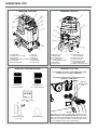
SPEEDSTER® LTD3
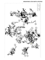
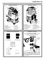
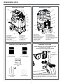
SPEEDSTER® LTD3 FRONT
SPEEDSTER® LTD3 BACK
1
12
13
2
3
11
4
10
14
23
5
22
9
21
20
6
8
7
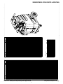
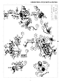
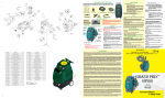
1. Switch Plate
2. 2” Male Cuff-Lynx™ Inlet
3. Prime Value
4. Female Quick Disconnect (QD)
5. Front Handle
6. Pressure Regulator
15
19
18
7. Front Fan
8. Side Vents
9. Solution Lid
10. PSI Gauge
11. Recovery Lid
12. Push Handle
17
13. Recovery Tank
14. Solution Tank
15. 4” Locking Casters
16. 10” foam filled
semi-pneumatic wheels
17. Hour Meter
18. Power Cords
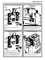
SPEEDSTER® LTD3 ITEMS INCLUDED
16
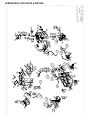
19. Auto Fill/Pump Out
Hose Connections
20. Solution Tank Drain
21. Service Latches
22. Rear Vacuum Exhaust
Optional Muffler Port
23. Recovery Tank Drain Valve
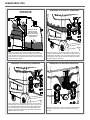
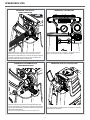
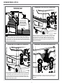
SPEEDSTER® LTD3 CORD
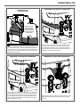
(Primary) Right Cord: Plug in yellow-tagged power cable
for Power To Vac 1, Pump, & 600W Heater.
(Secondary) Left Cord: Plug in power cable for Vac 2,
Pump-Out & 1,000W Heater.
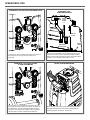
H110 Cuff-Lynx™
2” x 2” Hose Adapter
Yellow tag
indicates primary
cord.
H141 Cuff-Lynx™
2” x 1.5” Hose Reducer
FILTERS
G008 - Pack of Piglet™
filters
H375 - Hose Hanger
(4) screws
Plug each power cord into a separate, 20A grounded wall outlet.
Outlets must be on two separate breakers. When the amber
light on the switch plate illuminates and the audible tone sounds,
the machine is on separate circuits (not necessarily 20A circuits).
You can identify the primary cord by the yellow tag.
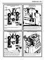
H226 Drain Elbow
2