1
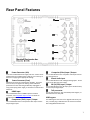
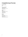
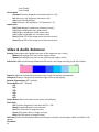
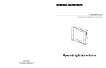
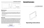
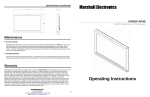
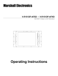
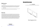
Model V-LCD70-AFHD Operating Instructions 1 This page intentionally left blank 2 Table of Contents Top and Front Panel Features ............................................................................................................................6 Rear Panel Features............................................................................................................................................7 Compatible Input Formats..................................................................................................................................8 MAIN MENU AND NAVIGATION .........................................................................................................................9 Using the Menu buttons ..................................................................................................................................................................9 Picture Submenu ..............................................................................................................................................................................9 Video & Audio Submenu ................................................................................................................................................................10 Setting Submenu ............................................................................................................................................................................11 OSD Submenu.................................................................................................................................................................................12 Specifications....................................................................................................................................................13 Maintenance.....................................................................................................................................................14 Warranty...........................................................................................................................................................14 3 4 ■ Included Accessories Carefully unpack the V-LCD70-AFHD monitor and verify that the following items are included: • V-LCD70-AFHD Monitor • 12V 1.5A XLR Power Supply Inspect the unit for any physical damage that may have occurred during shipping. Should there be any damage, immediately contact Marshall Electronics at (800) 800-6608. If you are not located within the continental United States, call +1 (310) 3330606. ■ Connections, Power-On and Initial Setup Plug the power supply into an AC power source (100-240 V @ 50/60 Hz). Attach the Power connector to the back of the monitor. Connect the required cables for video signal input and output. (Power must be applied to the V-LCD70-AFHD for the active loopthough output to be activated). Press the power switch on the front of the unit. Video will automatically be detected and displayed on the screen after selecting the proper input. 5 Top and Front Panel Features Power Switch This power switch controls power to the monitor from the DC Power Connector or the custom Battery Adaptor. The monitor will always attempt to draw power from the DC connector first if both the DC Power Connector and a Battery are installed simultaneously. This switch turns the panel on or off. Function Buttons Two user-definable function buttons can be used for direct access to various settings. Functions are assigned using the onscreen menu. Input Select Button Use the Input select button to switch between the different available video inputs. Menu Navigation Buttons Use the Menu, ↑, ↓, , buttons to display and navigate the on-screen menu. 6 Stereo Headphone Jack The 1/8” Headphone jack on monitor’s side takes two channels of embedded (or analog) audio and provides audio to connected headphones. Tally LED The Tally LED is illuminated, either Green, Red or Yellow, by connecting the appropriate pin on the tally connector to Ground. Rear Panel Features Power Connector (XLR) Insert the included XLR Power Supply end here. Power can be supplied from the included power supply or from a variety of DC sources supplying the appropriate voltage. Power Connector (Coax) Additional connector for Coaxial Power Supplies. Insert the coax end here, and tighten the locking nut for additional protection from the cord being accidentally unplugged. If using a third party power supply, it should have a 5.5mm OD x 2.0mm ID. HDMI Input The V-LCD70-AFHD has one HDMI input that is HDCP compliant. See Compatible Input Formats for details on accepted formats. Component (YPbPr) Input / Output The V-LCD70-AFHD has one Component video input and one loop through output. Composite (Video) Input / Output The V-LCD70-AFHD has one Composite video input and one loop through ouput. Stereo Audio Input The V-LCD70-AFHD has Left and Right Analog inputs. Access these via the RCA connector inputs. SDI (3G/SDI) Input / Output The V-LCD70-AFHD has one SDI input (up to 3G SDI formats) and one loop through output. Tally connector Use the Tally connector, with associated pinout diagram, to illuminate the front Tally LED. USB Program The USB Program connector is for Upgrade and Factory use only. Do NOT plug a USB cable into this connector without first calling Marshall Electronics. 7 Compatible Input Formats Composite (Video) NTSC PAL Component (YPbPr) 720p/50, 59.94, 60 1080p/23.98, 24, 25, 29.97, 30 1080i/50,59.94,60 HDMI 720p/50,59.94,60 1080p/23.98, 24, 25, 29.97, 30 1080i/50,59.94,60 1080p/50,59.94,60 3G-SDI 480i, 576i 720p/50,59.94,60 1080p/23.98, 24, 25, 29.97, 30 1080i/50,59.94,60 1080p/50,59.94,60 (3G Level A) 8 MAIN MENU AND NAVIGATION Access and navigate the main menu using the Menu button on the keypad: Using the Menu buttons • • • • Press the MENU button to enter the main menu. Use the and buttons to scroll through the main menu or each submenu. Press the and button to enter a submenu or choose a setting. Press the MENU button to exit the main menu, or return to the main menu from a submenu. Picture Submenu Contrast (0-100, 50 = default) Brightness (0-100, 50 = default) Saturation (0-100, 50 = default) Tint (0-100, 50 = default) Sharpness (0-100, 0 = default) Color Temp (6500K = default) 6500K 7300K 9300K User (0-255, 128 = Default) Color TempR 9 Color TempG Color TempB Picture Mode Standard (Contrast, Brightness, Saturation and Tint = 50) Soft (Contrast = 40, Brightness, Saturation = 45) User (User Defined settings) Vivid (Contrast = 60, Brightness = 55, Saturation = 75) Aspect Ratio Full Screen (Image is scaled across the entire screen) 4:3 (Image is displayed in a 4:3 aspect ratio) 16:9 (Image is displayed in a 16:9 aspect ratio) 14:9 (Image is displayed in a 14:9 aspect ratio) Zoom1 (Scale 45% of the image across the entire screen) Zoom2 (Scale 50% of the image across the entire screen) Video & Audio Submenu Peaking (Superimpose red highlight over parts of the image that are in focus) Mode1 (red highlight over parts of the image in focus) Mode2 (red highlight over parts of the monochrome image in focus) False Colors (Adds visual filtering to determine IRE levels in the image according to the chart below) Exposure (Adds red-striped overlay to areas of the image that may be overexposed) Histogram (Display a histogram on the bottom right corner of the display) Squared Segmentation (OFF = default) Screen Markers (OFF = Default) OFF 96% 93% 90% 85% 80% Center Marker (Places cross-hairs at the center of the display) Check Field OFF (Contrast, Brightness, Saturation and Tint = 50) Mono (Images displayed in monochrome) Red (Only red colors in image are seen) Green (Only green colors in image are seen) Blue (Only blue colors in image are seen) H/V Delay (Picture is shifted horizontally and vertically to check for ancillary data, HANC and VANC in SDI signals) Scan Mode 10 Standard (Normal image display) Overscan (Displays 95% of the image to avoid showing ancillary data “artifacts”) Underscan (Displays all available image data, including ancillary data “artifacts”) Volume (0 – 100 , 50 = Default) Balance (-10 - +10 , 0 = Default) Audio Meter (Displays an audio meter with the first two channels of available audio) Setting Submenu Image Flip (Flip image display) V (Flips the entire image vertically) H (Flip the entire image horizontally) V/H (Flip the image vertically and horizontally, or 180°) PIP (Picture in Picture, allowing the display of two images on the screen simultaneously) PIP Mode OFF Small (Small secondary image) Medium (Medium secondary image) Large (Large secondary image) PBP POP PIP Source AV (Composite video input is selected as the second image) Component (Component video input is selected as the second image) PIP Position Upper Left Upper Right Lower Left Lower Right PIP Swap (Swap position of the main image with the position of the second image) F1 (Places cross-hairs at the center of the display) F2 OFF (Contrast, Brightness, Saturation and Tint = 50) Mono (Images displayed in monochrome) Red (Only red colors in image are seen) Green (Only green colors in image are seen) Blue (Only blue colors in image are seen) Language (English, Espanol, English = Default) Reset (Return all settings to the Manufacturer Default settings) 11 OSD Submenu Horizontal Position (0-10, 5 = Default) Vertical Position (0-10, 5 = Default) Horizontal Size (0,3,5,7,10, 5 = Default) Vertical Size (0,3,5,7,10, 5 = Default) OSD Horizontal Position (0-100, 50 = Default) OSD Vertical Position (0-100, 50 = Default) Menu Transparency (0-10, 0 = Default) OSD Timeout (5 sec,10 sec,15 sec,60 sec, 5 sec = Default ) 12 Specifications ■ PANEL Screen Size Display Area (h x v) Pixels Brightness Contrast Ratio ■ 7” Diagonal 153.6 x 90 mm 1024 x RGB x 600 500 cd/m2 700:1 CONNECTORS HDMI Video Input 1 x HDMI Female Receptacle Stereo Headphone Jack 1/8” (3.5mm) Female Jack Video Input / Output 1 x BNC Female connector (Video Input) 1 x BNC Female connector (Video Output) Component Input / Output 3 x BNC Female connectors (Y, Pb, Pr Input) 3 x BNC Female connectors (Y, Pb, Pr Output) Audio Input 2 x RCA Female connector (L, R) SDI Input / Output 1 x BNC Female connector (SDI Input) 1 x BNC Female connector (SDI Output) Power Input XLR 4-Pin DC Connector (Power Supply side) 5.5 x 2 mm (Outer Diameter x Inner Diameter) . 13 Maintenance ■ Screen Cleaning Periodically clean the screen surface using ammonia-free cleaning wipes (Marshall Part No. V-HWP-K). A clean micro-fiber cloth can also be used using only non-abrasive and ammonia-free cleaning agents. Do not use paper towels. Paper towel fibers are coarse and may scratch the surface of the polycarbonate faceplate or leave streaks on the surface. Antistatic and fingerprint resistant cleaning agents are recommended. Do not apply excessive pressure to the screen to avoid damaging the LCD. ■ Faceplate Dusting Dust the unit with a soft, damp cloth or chamois. Dry or abrasive cloths may cause electrostatic charge on the surface, attracting dust particles. Neutralize static electricity effects by using the recommended cleaning and polishing practice. Warranty Marshall Electronics warranties to the first consumer that this V-LCD70-AFHD LCD monitor will, under normal use, be free from defects in workmanship and materials, when received in its original container, for a period of one year from the purchase date. This warranty is extended to the first consumer only, and proof of purchase is necessary to honor the warranty. If there is no proof of purchase provided with a warranty claim, Marshall Electronics reserves the right not to honor the warranty set forth above. Therefore, labor and parts may be charged to the consumer. This warranty does not apply to the product exterior or cosmetics. Misuse, abnormal handling, alterations or modifications in design or construction void this warranty. It is considered normal for a minimal amount of pixels, not to exceed three, to fail on the periphery of the display active viewing area. Marshall Electronics reserves the option to refuse service for display pixel failure if deemed unobtrusive to effective use of the monitor by our technicians. No sales personnel of the seller or any other person is authorized to make any warranties other than those described above, or to extend the duration of any warranties on behalf of Marshall Electronics, beyond the time period described above. Due to constant effort to improve products and product features, specifications may change without notice. 14 This page intentionally left blank 15 1910 East Maple Ave. El Segundo, CA 90245 Tel: (800) 800-6608 / (310) 333-0606 • Fax: 310-333-0688 www.LCDRacks.com • [email protected] 16