1
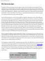
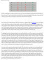
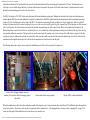
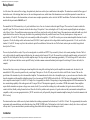
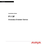
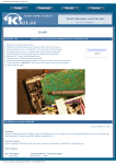
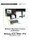
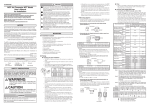
Modifications to the Ameritron AL-1200 Amplifier
W8WWV - Modifications to the Ameritron AL-1200
Amplifier
Greg Ordy
●
●
●
●
●
●
Introduction
EBS-1 Electronic Bias System
❍ Installation
Relay Board
❍ Installation
Conclusion
Epilogue 1
Epilogue 2
www.r6-ru4montesecchieta.it
IZ5CCV
Introduction
[This page describes two modifications I made to my AL-1200 amplifier. The mods were obtained from Ameritron, so they are official. It is my understanding that
these mods could be made to many of the Ameritron amplifiers, and even Amateur Radio linear amplifiers made by other companies. One of the modifications (the
relay board) is now (2002) apparently standard on many Ameritron amplifiers. I do not know if the other modification is or will become standard.]
I've used the Ameritron AL-1200 linear amplifier for several years (since the end of 1997). This amp gets high marks due to the reliability of the rugged 3CX1200A7
tube and the beefy power supply. It is an instant-on (10 seconds) amplifier, and operates on all amateur bands (including WARC) from 160 through 10 meters. My amp
will (easily) reach the full legal power limit (in the United States) when driven with slightly less than 100 watts. The amp I use is shown on another web page. I drive it
directly from my ICOM 756PRO, without use of an intermediate isolation control relay. I do not use the ALC line, since the drive of the radio is under the 120 watt
input limit of the amplifier.
Alas, nothing seems to be perfect. I do have a few issues.
http://www.seed-solutions.com/gregordy/Amateur%20Radio/Experimentation/AL1200.htm (1 di 16)22/10/2009 10.36.25
Modifications to the Ameritron AL-1200 Amplifier
For some reason, this amp, and the Ameritron AL-811H I owned before it, seem to blow out meter bulbs every few months. The front panel meters are illuminated
with miniature light bulbs. At best, they last only a year or so. Your Ameritron amp may be different in this regard. After 3 of the 4 bulbs died in my AL-1200 (in
approximately one year of operation), I did pick up some replacements. In fact, I happened to be at the Dayton Hamvention, and when I mentioned the problem to an
Ameritron representative, he presented me with 4 bulbs - for free. I appreciated that gesture, and when I replaced the bulbs in the meters, I added 10 ohm resistors in
series with the bulbs. The light output has been reduce just a little, but the bulbs have been working for a long time - much longer than they initially did without the
resistors. Even a small reduction in bulb voltage will probably lead to a greatly increased bulb life [please see the comments at the end of the conclusion].
Most amplifiers seem to have too much fan noise, and this one was no exception. Since I do not tend to operate any of the continuous duty modes (RTTY, SSTV, etc.),
I was able to lower the fan speed and reduce some of the noise. There are several different fan speed positions, and they can be selected by opening the amp cabinet
and moving a (soldered) jumper wire.
My final issue was the main relay noise. The amplifier used a typical open-frame relay bolted directly to the chassis. The relay does click and clack as it opens and
closes. Ameritron does sell a full-QSK board which will bypass the relay, but this is a rather expensive option (the QSK-5, approximately $250 (USD) for the internal
board, $350 for the external unit).
On top of the relay sounds, I started to detect a very short burst of noise in the radio receiver when returning to receive from transmit. This would only happen on some
bands, usually on and above 14 MHz. My own guess was that the relay contacts in the amplifier had developed some pitting or defect that caused noise during the
change-over between modes. I usually wear headphones when operating, so the little burst from the receiver was quite obvious. This noise seemed to developed over
time, so it is not part of the intended operation of the amplifier, or my overall setup. Something changed. From time to time I have tried to tune up on the wrong
antenna, and I have no doubt that I have abused that poor little relay. I more and more wanted to change the main relay - to hopefully get rid of the receiver noise, and
to find a quieter alternative.
Around the beginning of 2002 I became aware of the fact that Ameritron had a new relay design, which was being incorporated into the AL-1200, AL-1500, and AL82 amplifiers. These amplifiers are nearly identical, sharing a common chassis and power supply, mainly differing in the tube(s). I decided to email Ameritron and see
if this change was available as an upgrade for my AL-1200. At the same time, I saw that they had a new electronic bias upgrade that reduces quiescent current
whenever the power into the amplifier drops below 100 mW. The Internet web page on the EBS-1 (electronic bias system) indicated that it might reduce receiver noise
on break-in CW, which seemed to be related to the noise problem I was having. So, both of these modifications seemed like good enhancements to my amplifier. If
nothing else, there are so many screws (31, I was told) holding the cabinet top that once you have it off, you might as well make as many changes you can. By the way
the screws seem to easily strip, and the special retaining nuts that are pressed into the cabinet can pop off. A better implementation should be possible.
I placed a telephone order directly with Ameritron, and about a week later, on February 26, 2002, I received my two modification kits. The remainder of this page
describes those two modifications, their installation, and how the modified amp performs.
The electronic bias modification is called the EBS-1, and cost approximately $40 (USD, 2002). The new relay board cost approximately $35 (USD). The relay board
appears to be a recent addition, and does not (yet) have a specific part number (but there is a board number, see the relay board section). Here is a picture of the two
small circuit boards, shortly after they arrived.
http://www.seed-solutions.com/gregordy/Amateur%20Radio/Experimentation/AL1200.htm (2 di 16)22/10/2009 10.36.25
Modifications to the Ameritron AL-1200 Amplifier
EBS-1 Electronic Bias and Replacement Relay Boards
The boards are shown on top of 1/4 inch grid paper. The parts in the plastic bag above the EBS-1 board (on the left) are the mounting hardware for the board and a
MOV. The parts above the relay board include some diodes and filter capacitors used to provide a +25 to +30 Volt DC supply (for the new relays). The relays are
enclosed in the orange cases.
NOTE: Potentially lethal voltages and currents exist within the amplifier. Follow all Ameritron instructions, as well as accepted high-voltage safety
procedures. This page describes my personal experiences, and is not intended to act as, or be a replacement for, instructions. Please do not kill yourself, and
don't blame me.
http://www.seed-solutions.com/gregordy/Amateur%20Radio/Experimentation/AL1200.htm (3 di 16)22/10/2009 10.36.25
Modifications to the Ameritron AL-1200 Amplifier
EBS-1 Electronic Bias System
The unmodified AL-1200 uses a pair of mechanical relay contacts to supply a bias voltage to the tube when the amplifier is placed into transmit mode. The bias is
inserted into the center tap of the filament transformer secondary winding. According to the instruction manual, the plate (anode) current when in transmit mode, but
without an RF input signal, is 40 mA in the CW bias position, and 150 mA in the SSB position. These are typical numbers, the manual describes a 25 percent variation
due to line voltage and component differences. Multiplying the current by the nominal plate voltage of 3600 volts will tell us the power being consumed in this state.
40 mA X 3600 volts = 144 watts. 155 mA X 3600 volts = 558 watts. This power is consumed without producing any output signal, after all, there is no input signal.
So, it is wasted power, and a source of heat as well as wear and tear on the amplifier.
In order to reduce this quiescent power to a very low level, what you would like to do is apply the bias voltage only when it is needed - when an actual RF signal is
present at the input to the amplifier (and you are in transmit mode!). The EBS-1 performs that function. A pair of diodes act as a classic RF detector, and enables the
bias only when they sense an input signal of 100 mW or greater. The instructions also claim a small amount of hang-time before the bias is shut off. The hang time is
specified as 150 mS (0.15 seconds). The bottom line is that the tube bias will tend to follow the CW pulses or SSB waveform, being cut off when input RF is not
present (below 100 mW for 150 mS). The actual power savings will depend upon the duty cycle of the input signal, and the length of the gaps between CW pulses and
spoken words. On SSB, the carrier suppression of the transmitter may become an issue. If the transmitter is rated at 100 watts of output power, the 100 mW level is 30
dB below that level. 100 watts to 10 watts to 1 watt to 0.1 watts - 3 orders of magnitude, or 30 dB. If your 100 watt radio does not have at least 30 dB of carrier
suppression, you might not turn off the bias because the RF input never drops below 100 mW. If you don't see the bias falling to zero when the SSB audio is removed,
you might need to check your carrier suppression. 30 dB of carrier suppression should be easily achieved with most modern SSB transmitters, unless they are defective
or misadjusted. As an example, the ICOM 756PRO is specified as having 40 dB of carrier suppression.
Other factors will influence the minimum power output of your SSB transmitter. For example, if you are using compression on your voice, either AF or RF, you may
create a background power level which is greater than 100 mW. The classic situation is when you can hear a constant background noise, such as a fan, when a station
transmits. Since you can always hear something, the output obviously does not drop substantially when the voice is removed. In this case, the bias will never be turned
off in the amplifier since RF is always being applied to it. The goal of compression is to increase the average talk power, and a common side-effect is that the minimum
output power is increased. It doesn't take much to go over the 100 mW level.
The CW considerations are a little different. In CW, it is assumed that the transmitter power will drop to under 100 mW when the key is up. The issue is the hang-time.
At some CW speed, the longest of the gaps, the gap between words, will be less than 150 mS. At that point, the bias will never be turned off. AC6V has a web page
which describes the timing of CW elements. For our purposes, we care about the times when there is no signal - the gaps. There are three types of gaps. The gap
between elements within a character, the gap between characters, and the gap between words. In the standard Paris timing (see the AC6V page), the ratio between
these gaps is 1:3:7. In addition, at 10 words per minute (WPM), the smallest (fastest) gap consumes 120 milliseconds. Here's a table that shows the gap times for a
range of CW speeds.
CW Timing Chart (in milliseconds)
Speed (WPM)
Element Spacing (X1)
Character Spacing (X3)
Word Spacing (X7)
10
120
360
840
http://www.seed-solutions.com/gregordy/Amateur%20Radio/Experimentation/AL1200.htm (4 di 16)22/10/2009 10.36.25
Modifications to the Ameritron AL-1200 Amplifier
20
60
180
420
30
45
135
315
40
30
90
210
50
26.25
78.75
183.75
60
22.5
67.5
157.5
Times above 150 mS are shown in green. The bias hang-time, when actually set to 150 mS, will turn off during that gap. Gaps shorter than 150 mS are shown in red the bias will not turn off. Of course even when the bias does turn off, the first 150 mS of the gap will be the hang-time, when the bias lingers. In other words, the first
150 mS of a gap in green is taken up by the hang-time. The actual bias-off time will be the total interval minus 150 mS.
Not all folks appear to approve of RF-actuated electronic bias circuits. Noted amplifier guru, Rich Measures, AG6K, on one of his pages, expresses concern that these
sort of bias circuits can lead to rough audio on softly spoken syllables, and an increase in the IMD products of the amplifier. Perhaps the 150 mS hang time of this
design will reduces the rapid bias switching that he is concerned about? The RF trigger level will also determine the characteristics of the RF-actuated electronic bias
circuit. The EBS-1 instructions claim that the turn-on time of the new bias system is 20 uS (microseconds). They further go on to say that the fast rise time, coupled
with the relatively small bias change from class B to near class AB insures that spatter and distortion are not added to the signal. I lack the background and test
equipment to know the real answer, so I'll just trust that this is a factory mod from the maker, and that they know what they are doing.
This does bring up the general topic of timing and sequencing between receive and transmit (and back to receive). When an innocent event, such as pressing the CW
key or PTT switch occurs, a rather complex chain of events begins, as the various functional blocks in the system begin to switch from one mode to another. Timing
and sequencing are critical in order to prevent damage and to provide desired functionality. Of importance to this page is the idea of hot switching, where RF is applied
to a relay which is in the process of either closing or opening. This is a highly undesirable situation, because the relay contacts will tend to arc at some point since the
changing contact gap will certainly be small enough to allow arcing. At one extreme, the arcing will literally weld the contacts shut. At the other extreme, even small
amounts of arcing will lead to premature failure of the relay (due to contact pitting and carbon build-up). So, RF must be kept out of the signal chain until all of the
relays are switched. Of course we want to quickly switch between receive and transmit, so we cannot simply add significant delay before the transmitter starts to pump
out RF. In fact, full break-in QSK CW demands that the system switch between receive and transmit each time the key is closed (and back to receive when the key is
opened). So, we have to carefully design the total system to minimize the switching time without introducing hot switching.
In some cases, an interface is required between the transmitter and the amplifier. This is usually needed to connect together two devices with incompatible interface
specifications. For example, the transmitter keying relay might be a small reed relay designed to switch 12 volts at a very small amount of current. The amplifier,
however, might require 120 volt AC switching. Clearly, you can't just connect the amplifier directly to the transmitter. You need some sort of (buffer) interface. A
number of commercially constructed interfaces are available, although they are not difficult to build. So far, I have been able to avoid needing an interface through the
dumb luck of the particular transmitters and amplifiers I have selected. If, however, I needed an interface, I would certainly build one myself, and make it out of
transistors, as opposed to a relay. A transistor interface would be much more reliable, and silent, and add very little additional delay in the switching chain. Every
millisecond of delay added between the transmitter and the amplifier increases the risk of hot switching. Don't add an interface unless you need one, and if you need
one, insert the smallest possible additional delay. Your amplifier will thank you.
http://www.seed-solutions.com/gregordy/Amateur%20Radio/Experimentation/AL1200.htm (5 di 16)22/10/2009 10.36.25
Modifications to the Ameritron AL-1200 Amplifier
I chose to add the EBS-1 modification before the relay board modification. It seemed like the safer and less-extensive modification. The instructions were also clearer
and more complete. The two modifications do interact. In the unmodified AL-1200, the bias voltage is sent through the single main transmit relay, which is a 3-pole
relay. One set of contacts switches the input RF signal, the second set switches the output RF signal, and the third set switches the bias voltage. The new relay board
uses two separate relays, each being double pole, double throw. One set of contacts on the input relay are used to switch the bias voltage, just as in the original
amplifier. So, if I could convince myself that I had successfully made the EBS-1 modification, moving to the relay board modification would be relatively easy, at least
in terms of understanding what was going on with the bias line.
Installation
The EBS-1 implementation consists of two circuit boards, the detector board and the bias board. As delivered, the two boards are joined into one by small arms of
board material. If you look closely at the previous picture, you'll see that the left edge of the board is only connected to the rest of the board by small pieces of material
at the top and the bottom. The intent is that you clip the two bridging pieces, creating two separate boards. This step is not called out in the written documentation, but
does appear in a drawing, when the detector board is described as the break-off circuit board. So, take a sharp diagonal cutter and snip the boards apart. Note that the
smaller detector board mounts over the bias board, sharing two of the four corner mounting screws.
The most complex part of the whole EBS-1 modification is mounting the bias board. The four corners each require a single #6 mounting bolt. According to the
instructions, recent runs of the amplifier will come with the mounting holes already drilled. If you do not have the holes, however, you will need to drill them. This is a
substantial increase in the total amount of work involved. As the instructions detail, before you drill the chassis you must remove the power tube(s) and transformer.
The holes are 5/32 inch in diameter. The instructions come with a template which can used to locate the four holes.
My amplifier is about 5 years old (1997 vintage) and has a serial number of AL-12-12020. It did not have the mounting holes. I would expect that only very recent (end
of 2001) amplifiers would have the holes. So, I had to remove the tube and the transformer. This is not as much work as it might seem, since the amplifier is shipped
with the tube and transformer in separate boxes. The instructions are quite detailed on their installation, and the removal is the obvious reverse procedure. Still, it takes
time.
Before I took the amplifier off of the desk, I used the front panel meter to measure the plate current at idle. I measured 100 mA on SSB, and 25 mA on CW. These
values are below the nominal values listed in the manual. I suspect that the meter is not very accurate at the low end of the range, where each tick mark is 25 mA. After
all, it measures all the way up to 1000 mA (1 amp).
I photocopied the page from the written instructions to get a copy that I could cut out. I made 4 small holes (in the paper) directly over the target drilling points. Once I
had located the template on the wall of the amplifier (with a piece of tape), I drew over the holes with a red marking pen, leaving 4 clear indications of where to drill.
Here's where it's necessary to have a very sharp drill bit and a good drill. After drilling the holes, be very sure to get all of the filings out of the amplifier.
With the board mounted, wiring is trivial. Four wires are involved. One is a jumper between the bias board and the detector board. The second wire connects to a
nearby terminal strip where it samples the incoming RF. The third wire is the bias line that previously went directly to the main T/R relay. It is removed from the relay,
http://www.seed-solutions.com/gregordy/Amateur%20Radio/Experimentation/AL1200.htm (6 di 16)22/10/2009 10.36.25
Modifications to the Ameritron AL-1200 Amplifier
and attached to the board. The fourth and last wire connects from the bias board back to the now unconnected terminal on the T/R relay. The bias board is now
effectively in series with the original bias line. It will control the bias line in response to the presence of RF on the detector board. A ground connection is made
through the metal mounting spacers, back to the center divider.
The EBS-1 kit includes a 50 V MOV which is placed between the filament transformer and ground. Although not discussed in the written circuit description, one
assumes that this MOV provides some additional circuit protection that relates to the EBS-1 modification (the documentation notes that the maximum open circuit
voltage is 50 volts, which happens to be the rating of the MOV). The instructions concerning this part are rather terse. Step 10 simply states: Solder the red MOV
between the filament transformer terminal containing the bare wire to the zener diodes and the ground lug of the terminal strip. My first question was: What terminal
strip? Up to this point, all of the attention was directed at the terminal strip near the mid-rear of the center divider. Where is this terminal strip? Fortunately, the
filament transformer is near the front of the case, and directly above it was a terminal strip with the transformer secondary wires destined for the tube. The center lug
was grounded, and had no connections. The lug near the rear was the center tap of the secondary, since it was a red wire with a white stripe, as opposed to the other
two plain red wires. In addition, the center tap wire connected to a bare wire that actually was one end of the zener diode bolted to the center divider. In the end, the
instructions and the amplifier made sense, but I wish that the documentation was a little more clear on this point.
The following three pictures capture various steps in the installation process. Please click on a picture for a larger view.
Center divider with paper template, ready for
marking. The actual bias board is leaning up against
the divider.
Board mounted with wiring complete.
Mystery MOV on front terminal strip.
When this modification is added, the written instruction manual will no longer be correct when it describes the current flow in CW or SSB mode when the amplifier is
keyed, but not driven. This is the no drive current. In my manual, which is marked as Rev. 3, the paragraph that is no longer correct is paragraph #7, on page 9. Of
course the whole point of this modification is to reduce the no drive current to zero.
http://www.seed-solutions.com/gregordy/Amateur%20Radio/Experimentation/AL1200.htm (7 di 16)22/10/2009 10.36.25
Modifications to the Ameritron AL-1200 Amplifier
Relay Board
As of the time of the creation of this web page, the updated relay board was a relatively new modification to the amplifier. The instructions consisted of three pages of
hand written notes. After studying them, however, the circuit changes made sense, and the form of the information was not really that important. I assume that over
time Ameritron will improve the documentation, and create a more complete presentation, such as exists for the EBS-1 modification. The board and the instructions are
marked with the part number: 861-0453, rev 2.
The unmodified AL-1200 transmit relay is a 3-pole, double throw device. One set of contacts switches the input RF signal. The second set of contacts switches the
output RF signal. The final set of contacts switches the bias voltage. This part has 11 wires, including the coil. The relay board conceptually duplicates and replaces
each of those 11 wires. The modification centers on moving each of those wires from the relay to the board. Some of the connections are made with small coax, which
implies that shields are involved. In my amp, the shields were grounded right before they reached the new board. The relay board requires a voltage source of
approximately +25 volts DC. This voltage level is not normally available in the amplifier. +12 volts DC is used to power various internal amplifier functions. In order
to generate +25 volts, the bridge rectifier on the meter board (50-01140-1) must be replaced with a voltage doubler circuit that generates the +25 volts, as well as the
standard +12 volts DC. In many ways this is the most drastic part of the modification. Parts must be cut off of the board, and new parts are added, being soldered
directly to the PC traces.
The new relay board holds two relays. They are the same physical size, and both are DPDT. They are made by Schrack, with a country marking of Austria. The first
relay, which switches the amplifier input and the tube bias, has contacts rated at 8 amps at 250 volts. The second relay switches the amplifier output, and is rated at 16
amps at 250 volts. Both poles of the relay switch the amplifier output. The relays are quite small, measuring approximately 1.125 inches long, and 0.5 inches wide as
well as tall. I get the sense that these are not special RF relays, but rather common commercial/industrial parts designed for switching AC (from a wall outlet, for
example).
One issue that always comes up with using an external amplifier is the rating of the switching line that puts the amplifier into transmit mode. In order to key the
unmodified AL-1200, you need to ground the relay control input. The input is at 12 volts DC, and you need to be able to sink 100 mA of current. This was the
specification of the transmit relay coil in the unmodified amplifier. The transmitter must be able to drive the amplifier input, or, you need some sort of interface which
keeps the transmitter and the amplifier within their ratings. I have been using an ICOM 756PRO radio with the AL-1200. The rating in the manual for the transmit/
receive amplifier control output is 16 volts DC at 2.0 amps. Now it is apparently true that the 2.0 amp rating is a long-standing misprint in ICOM documentation. The
true current sinking capability of the radio appears to be 0.2 amp, or 200 mA. This misprint is apparently in a number of ICOM radio manuals. Some amplifiers
require that the transmitter accept more voltage, more current, or both. If you overload the switching relay in the transmitter, the typical outcome is that the relay
contacts stick shut, literally welding themselves closed. Since the fix for this problem can be expensive, it's good to make sure that your transmitter and amplifier are
compatible, or that you use an appropriate interface. [NOTE: an interface relay will potentially change the transmitter/amplifier timing. See the related comments in the
EBS-1 section]
The instructions that came with the new relay board claim that the switching requirements for the board are 12 volts DC at 110 mA. The is approximately the same the
requirements in the unmodified amp, and within the rating of my ICOM 756OPRO radio. The bottom line is that I could continue to directly drive the new relay board
with my radio. If you are uncertain about your radio and amp, please double check the ratings so that damage is avoided.
Installation
http://www.seed-solutions.com/gregordy/Amateur%20Radio/Experimentation/AL1200.htm (8 di 16)22/10/2009 10.36.25
Modifications to the Ameritron AL-1200 Amplifier
If the EBS-1 modification was algebra, the relay board modification is graduate advanced calculus. The three pages of handwritten instructions are somewhat like
following a treasure map. The clues are there, but that's about it. As I did the installation, my whole approach to the modification changed. There are really three
different areas of change.
1. The existing mechanical relay is replaced with the new relay board.
2. A source of 25 - 30 VDC must be obtained to drive the relay board.
3. The front-panel transmit LED must be rewired to work with the new board.
The first question was where to mount the board. The obvious answer was in place of the old relay. Again, holes (three of them) must be drilled to mount the board,
but neither a template, nor the screws, were provided. A second part of that first question was the board orientation. By orientation I mean whether the top
(component) side of the relay board faces towards the center divider, or faces out. Normally, most PC boards tend be mounted with the back or rear side next to a wall
or partition. The rear side is usually somewhat flat, since it is consists of the solder bumps on the trace side of the board. So, with a few short spacers acting as standoffs, most boards can be mounted parallel to a flat surface.
In this case, after considering the location of the wiring points on the board, and the position and length of the wires removed from the mechanical relay, I decided to
mount the relay board with the bottom side facing into the open area of the cabinet, and the parts pointing towards the center divider. That may seem strange, but in the
end, it worked out well. By the way, the instructions do not indicate where or how to mount the relay board. I made this decision because this orientation made it
possible to reuse all of the existing wires that previously were connected to the mechanical relay. I certainly didn't want to start running 1500 watts of RF all over the
place, for no good reason.
In order to hold the board in that orientation, I needed to use some long spacers. Fortunately, I had a nice supply of nylon spacers, threaded for 4X40 bolts. Sadly, the
stand-off distance is critical. If you make it too short, the 2N3055 transistor on the board will touch the center divider. If you make it too long, the board will hit the
center pins on the rear-panel coax (SO-239) connectors. The spacing I used was approximately 7/8 inches.
I located the board in the upper corner of the rear edge of the center divider. Because other parts are mounted on the inside rear of the cabinet, it is difficult to drill two
of the mounting holes with a normal drill and drill bit. In the end, I needed to use a 5/32" drill bit which was 12 inches long. This long bit allowed me to get the body of
the drill outside the cabinet, and away from all of the parts mounted on the rear panel. With that bit, drilling the holes became easy. Perhaps one of those flexible drill
shafts could also be used. I used 4X40 bolts to hold the board to the spaces, and the spacers to the center divider.
I should also mention that the board is a single-sided PC board, without plated-through holes. By mounting the board with the traces facing out, all of the wiring points
were exposed.
Time for some pictures. Some of the parts in these pictures appear to be curved. That is simply the optical distortion caused by the close-up macro lens on the digital
camera. Please click on a picture for a larger view.
http://www.seed-solutions.com/gregordy/Amateur%20Radio/Experimentation/AL1200.htm (9 di 16)22/10/2009 10.36.25
Modifications to the Ameritron AL-1200 Amplifier
Relay board mounted in upper rear corner of center
divider.
Close-up of relay board.
New 24 Volt DC Supply.
The left picture shows the new relay board mounted in the upper rear corner of the center divider. The EBS-1 bias board, described previously on this page, is in the
lower right of the picture. If you return to the previous EBS-1 pictures, you can see the mechanical relay. When reassembled, the massive power transformer fills up
the open space in the picture.
The middle picture is a close-up shot of the relay board. The white wires moving off to the left are the connections to the SO-239 UHF jacks. The upper wire is the RFout, and the lower wire is the RF-in. The blue heat shrink near the board keeps those connections well-insulated. Except for several black ground wires visible on the
edges of the board, all of the remaining connections are made with the wire entering from the component side of the board, coming through the holes to the trace side
of the board. I soldered several of the wires to the trace side before mounting the board. There was enough slack in the lines to allow a small degree of movement. I
then mounted the board with 3 screws and completed the remaining connections. Mounting and wiring the board took several hours. Even detailed instructions would
not have helped. It is simply tedious to make sure that you are getting it correct. It's a small and cramped area. While I removed the transformer for the EBS-1
modification, I believe that you would also want to remove it to add the relay board.
The board came with grommets already installed in the three mounting holes. I don't know if that was done for electrical insulation or noise suppression purposes. The
grommets are visible in the middle picture, under the screw heads. Three ground wires are soldered to the board, and are attached to various points on the cabinet. The
instructions call for ferrite beads to be added to all of the connections that do not (intentionally!) carry RF. The beads are part of the modification kit. I held the beads
in place with small cable ties which were attached to the wire running through the bead. The cable tie is snugged down on the wire, and creates a stop for the bead.
Two of the beads can be seen in the middle picture. These two wires are the bias lines, from the EBS-1 board and to the tube filament transformer.
The relay boards requires a +25 volt DC power source. This power wire must be run through the cabinet, an existing line is not reused.
http://www.seed-solutions.com/gregordy/Amateur%20Radio/Experimentation/AL1200.htm (10 di 16)22/10/2009 10.36.25
Modifications to the Ameritron AL-1200 Amplifier
The second part of the modification involves providing a 25 to 30 volt DC power source for the relay board. The kit instructions have you modifying the filter board,
which is located on the front of the cabinet. The bridge rectifier which provides the 12 volt DC signal is replaced with two discrete diodes and a pair of filter capacitors
connected in the classic voltage doubler circuit. This provided both 12 and 24 volts DC. Although I started off to make this modification as suggested, in the end, I
decided not to do it.
First, I really did want a 25 volt DC supply in the amp. In the long run, I would like to install a vacuum RF relay (or two) in the amp, and all of the relays I have ever
seen operate from 24 volts DC. Providing 25 volts in the amp would pave the way for that future modification. The unmodified amp provided only 12 volts DC.
I had several concerns about modifying the existing board. First, it seemed to me that the quality of the DC regulation would go down, as a full-wave bridge was
replaced with what amounts to a half-wave circuit. I was also concerned that the 12 volt level might change. Since the meter illumination bulbs are sensitive to the
voltage level (they burn out if the voltage is too high), I didn't want to see the 12 volt level change - even by a fraction of a volt.
The suggested modification itself was difficult to implement. The filter board includes a rotary switch that selected various metering functions. The board is held in
place by the nut on the rotary switch shaft. The board is mounted vertically, right up against the front of the cabinet. To remove the board, you have to start to take
apart the front of the cabinet, in order to get to the retaining nut on the switch. Even with the switch loose, the board has little movement due to the large number of
wires in the surrounding area. In order to make the suggested modification, one would need to gain enough access to the board in order to remove several components
and add several components.
For all of these reasons, I decided to give up on the suggested power supply modification.
There were still choices to be made, however. In particular, how was I going to obtain 25 volts DC from what was available in the amp?
One idea was to use a DC - DC inverter. For $30, Jameco sells a small inverter that converts 9 to 18 volts DC into 24 volts DC. This would be one solution, but it
seemed rather expensive. Another choice was to use a 240 volt to 24 volt AC transformer. The problem with this approach was that the existing amplifier transformers
have adjustable taps to select different supply levels. There are taps for 208, 220, 232, and 245 volts AC. If I were to add a simple transformer which connected directly
to the house voltage, it would not have these different taps. With different supply voltages, the 25 volt DC level would also change. Several other options exist.
In the end, I decided to take the 12 volts AC feeding the existing 12 volt DC power supply and step it up to 24 volts AC by going through a back to back pair of 12 and
24 volt step-down transformers. In other words, I connected the secondary of a 12 volt transformer to the existing 12 volt AC supply. The primary of this transformer,
now stepped up to 120 volts AC, is connected to the primary of a 24 volt AC transformer (which steps it back down to 24 volts). A full-wave bridge and filter capacitor
completed the circuit. I mounted these parts on a double thickness of perfboard. The board is mounted vertically right behind the existing filter board. I now have a 24
volt DC supply without making extensive changes to the existing circuit. This is a brute force, but inexpensive solution. Still, space is at a premium, and any solution
must be one that fits in the available space. The benefit of this approach is that the two yellow wires carrying the 12 volts AC from the filament transformer are easy to
tap into, right before they attach to the filter board.
The additional DC power supply is shown in the above right picture. The bottom of the board is mounted to the bottom of the cabinet via an aluminum L bracket. The
first component on the bottom of the board is the 12 VAC to 120 VAC transformer. Directly above it is the 120 VAC to 24 VAC transformer. The top of the board
http://www.seed-solutions.com/gregordy/Amateur%20Radio/Experimentation/AL1200.htm (11 di 16)22/10/2009 10.36.25
Modifications to the Ameritron AL-1200 Amplifier
contains a terminal strip with the full-wave bridge rectifier, and a large filter capacitor. I also put a 0.01 uF capacitor across the output voltage in order to provide RF
suppression. For additional mechanical support I made up a ground strap that went between the top of the filter capacitor bank, and the new power supply board. This
strap was less than an inch of 12 gauge solid wire. It is very stiff, and insures that the power supply won't wiggle in the cabinet.
One of my concerns was that the output voltage of the new power supply would be in the range of 25 to 30 volts DC. This is the range specified in the instructions.
Variations in transformers can cause the output voltage to shift, especially if there is not a dedicated regulator circuit. In this case, I really had three transformers all in
series - anything could happen. I found that the DC output voltage of my board (no load) was 28 volts. Since the load of the relay board would no doubt pull that down,
I felt that I was right in the middle of the specified 25 to 30 volt DC range. By the way, the so-called 12 volt DC supply in my amplifier actually measured 13.4 volts.
No wonder the 12 volt meter bulbs tend to burn out quickly! If you expect and require that the 12 volts be 12 volts, you may want to check your amplifier.
The following picture shows the new power supply board mounted in the cabinet. If you look closely, you can see the ground strap going from the front corner of the
filter capacitor bank to the new board.
New Power Supply Board
The final part of the modification concerns the front panel LED which glows when you are in transmit mode. In the original circuit, a 33 ohm resistor was in parallel
with the LED. When in transmit mode, this combination had most of the 12 volts across it. In the new circuit, a 1 K resistor is placed in series with the LED, and the
http://www.seed-solutions.com/gregordy/Amateur%20Radio/Experimentation/AL1200.htm (12 di 16)22/10/2009 10.36.25
Modifications to the Ameritron AL-1200 Amplifier
majority of the 12 volts goes through the combination. So long as the LED is driven with 20 mA, and has approximately 1.6 volts across it, it will functional normally.
Given the low cost of a standard red LED, it may make sense to simply replace the LED so that you can get full length leads to work with. I replaced mine with an
LED that I had in the junk box which I know is at least 20 years old. It works just fine. Changing the LED is a difficult task, as there is little room to work, and you
have to push the retaining collar over the end of the LED while it is up against the front panel.
Conclusion
Both modifications functioned as expected. The new relay board is indeed quieter than the mechanical relay. Perhaps it's not so much the reduction in sound level, but
the change in the nature of the sound. The mechanical relay had a sharp clack sound - a metal on metal character. The new board (with two relays) has more of a flick
sound. Not as sharp, more mellow. I know that it sounds as if I am reviewing a wine or cheese, but it's how it sounded to me.
The open circuit voltage at the relay jack was measured at 11.6 volts. The short circuited current (amplifier now in transmit). was measured at 116 mA. I can continue
to drive the amplifier directly from my ICOM 756PRO radio.
The operation of the amplifier is unchanged, except that the idle plate current is now zero mA. As I write this page, I have not used the amplifier for more than a few
hours, but so far, so good. I think that I'll start to accumulate parts to replace the relay board with a vacuum RF relay. This will provide the quietest solution, and even
allow full QSK.
Although the EBS-1 modification was very simple, the relay board modification is not for the faint of heart. Perhaps as the instructions get better, it will be less of a
mystery. Still, expect to spend at least a full 8 hour day making the change. You'll need some good tools and a long drill bit.
I spent some time trying to find an improved meter illumination scheme. I believe that the source of the problem is that the stock light bulbs have a 12 volt rating, and
that they are driven with a higher voltage, around 13.5 VDC. As a result, bulb life is greatly reduced. The bulbs are soldered into the amp, and it's a lot of work to get
into the case due to the 31 or so screws that hold the top onto the chassis. So, replacing a burned out bulb is much more work than it might otherwise seem.
My first thought was to use LEDs. Over the years, the light output of LEDs has increased, and white light is now available. An LED which is not abused will tend to
last forever. Although I tried several alternatives, in the end, I did not find a solution I could live with. The light output of an LED tends to be more focused that a
traditional bulb, and the nature of the physical meter mounting does not provide many alternatives. The standard bulbs are mounted parallel to the meter case, and sit
right on top of the meter. The bulbs also clip into metal supports, and these supports just don't mate well with LEDs. I glued the LED to short sections of wooden
dowel, and clipped the dowel into the bulb holder. This caused the LED to point right into the meter movement, but the light was so focused that the meter face had
lighter and darker zones. I then increased the number of LEDs, up to 4 per meter. I had lots of light, but the illumination was still uneven. I don't want to discourage
this approach, however, since it is probably the best long term solution. I have heard for several amateurs who have adapted LEDs to the AL-1200, and they all seem
happy with the result.
Finally, the original replacement bulbs appeared on the Ameritron web site for $0.90 each. I'm sure that they were always available if you called, but it was nice to see
them as a line item on the product page. Then, I discovered a bulb with the same package available at hamfests. I was able to purchase a bag of ten for $1.00. The bulbs
were rated as accepting 12 to 14 volts. I went with the old technology and used these bulbs. My only modification to the original implementation was to use an 8-pin
connector to connect the bulbs to the power supply. Now, I can replace the bulbs without having to get out the soldering iron. I hope that these bulbs have a longer life.
http://www.seed-solutions.com/gregordy/Amateur%20Radio/Experimentation/AL1200.htm (13 di 16)22/10/2009 10.36.25
Modifications to the Ameritron AL-1200 Amplifier
If not, I will be back working with those LEDs, since they really are the way to go.
Epilogue
Modifying amplifiers is a popular activity, and I suspect that there are many small suppliers of various pieces and parts. One of them that I have recently learned of is
WD7S Productions. He sells a number of different subsystems designed for grounded grid triode amplifiers. The RF-1 Directional Coupler and QSK Transfer Relay
Board could probably be adapted to the AL-1200 (it appears as if bias switching would have to be done separately). This is a more extensive modification than the
Ameritron relay board, and would still need a 25 volt power supply. But, you would end up with a full-QSK amplifier with vacuum relays.
I mentioned AG6K, Rich Measures, eariler on this page. His web site contains a substantial amount of information on many different aspects of amplifiers. He also
sells a small number of parts related to amplifiers.
After my amplifier modifications were complete, the issue with the meter lamps really started to annoy me. The issue is that the standard Ameritron bulbs seem to burn
out in a very short time (perhaps a year or two), and if you add a dropping resistor, the bulb life is extended, but the light color starts to yellow. This might not be such
a problem if it didn't take 31 screws to get at the bulbs, and if the bulbs were not soldered in.
I have been working on a solution to this issue, but I'm finding it to be a challenge. If and when I find a solution (long-lasting, bright white, inexpensive), I'll post it on
this page.
In June of 2002, I exchanged several E-mails with Jeff, K5JP. Jeff had recently acquired a new AL-1200, and we talked about the modification state of his amplifier. I
learned that the relay change was made in October, 1999. Jeff was also kind enough to send me a picture of his relay board as he was installing the transformer and
tube into the amp. Here is his picture, on the left (click on the picture for a larger view). At around the same time, I received a similar picture from Brent, N5TML,
which is shown on the right. This picture is very close to the relay, and shows the signal wiring.
http://www.seed-solutions.com/gregordy/Amateur%20Radio/Experimentation/AL1200.htm (14 di 16)22/10/2009 10.36.25
Modifications to the Ameritron AL-1200 Amplifier
Factory Installed New Relay Board (courtesy of K5JP)
Relay Details (courtesy of N5TML)
I was very glad to see that I installed my board in the same orientation as the factory. You can also see two of the mounting holes for the EBS-1 board on the right edge
of the picture.
Epilogue 2
In April of 2004, I received some email from Floyd, K8AC, which contained a great suggestion on how to deal with the narrow focus on the standard LED. Here is
what Floyd shared with me.
I used the standard $3.99 Radio Shack bright white LED, and burnished the rounded end with
a piece of 600 grit emery cloth. That gave it a frosted look and the resulting light pattern is
pretty good. It's just a tad brighter in the center of the meter, but there are no shadows or
sudden light to dark transitions. After I saw the result, I thought that I could have easily put a
small dot of black paint in the center of the LED lens and thus evened the light out even
more. Since I ended up using silicone RTV to hold the LEDs in place, I never did get back
and try that.
http://www.seed-solutions.com/gregordy/Amateur%20Radio/Experimentation/AL1200.htm (15 di 16)22/10/2009 10.36.25
Modifications to the Ameritron AL-1200 Amplifier
This approach would seem to fix my only issue with the LED, which was the uneven illumination pattern, due to the sharper focus of the LED lens. Next time my
bulbs need changing, I'm going to give this a try.
Back to my Experimentation Page
Back to my Amateur Radio Page
Last update: Monday, April 12, 2004 10:22:00 AM
Back to my Home Page
http://www.seed-solutions.com/gregordy/Amateur%20Radio/Experimentation/AL1200.htm (16 di 16)22/10/2009 10.36.25