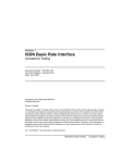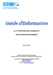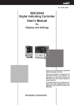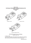
1
CP-UM-5573E CAUTION The MCF air flowmeter uses a µF (Micro Flow) sensor in its sensing unit. This manual explains the handling precautions, mounting, wiring, setting, operation and main specifications. See the "Installation & Configurations" and "Communications" manuals listed below for the detail handling procedures and the setting methods, etc. These manuals also contain information on using various functions. Please read if necessary. MCF Air Flowmeter USA Model User's Manual for Installation & Configuration CP-SP-1293E MCF Air Flowmeter USA Model User's Manual Communications CP-SP-1301E Check the following items when removing the MCF from its package: Part No. Q'ty 81424037-001 1 CP-UM-5573E 1 When maintaining or replacing the measurement module, release the internal pressure of this device before removing the measurement module. • Horizontal pipe with display facing to the right as seen from air inlet (Position 2) MOUNTING ■ Installation location Flow direction Avoid mounting this device in places characterized by any of the following: • Temperature below -10 °C or above 60 °C • Humidity exceeding 90 % RH • Sudden changes in temperature, or condensation • Corrosive or flammable gases • Heavy concentration of conductive substances (e.g. dust, salt or iron dust), water droplets, oil mist or organic solvents • Vibration or shock • Direct sunlight • Splashing by water or rain • Splashing by fluids (e.g. oil, chemicals) • Constant, heavy splashing by water or dust • Strong magnetic or electrical fields ■ Piping Remarks This Manual SAFETY PRECAUTIONS Safety precautions are for ensuring safe and correct use of this product, and for preventing injury to the operator and other people or damage to property. You must observe these safety precautions. Also, be sure to read and understand the contents of this user's manual. WARNING Warnings are indicated when mishandling this product might result in death or serious injury to the user. CAUTION Cautions are indicated when mishandling this product might result in minor injury to the user, or only physical damage to this product. CFH CF EV AL enter View from the air inlet Side view Operating Flow rate range Instantaneous flow rate deviation pressure range 0 to 1 MPa 5 to 100 % of full scale flow rate 0.5 % FS per 0.1 MPa ±1 digit or less -0.07 to 0 MPa 5 to 100 % of full scale flow rate 0.5 % FS per 0.01 MPa ±1 digit or less Example: When the MCF is mounted on horizontal piping with the display unit facing to the right as seen from the air inlet, the instantaneous flow rate deviation is 1.5 % FS ±1 digit or less as compared with the accuracy in the normal position at 0.3 MPa. 0.5 % FS / 0.1 MPa × 0.3 MPa = 1.5 % FS Model Pipe Recommended tightening number size torque [N•m] MCF0080 1/4 inch 12 to 14 MCF0150/0151 1/2 inch 31 to 33 MCF0250 1 inch 36 to 38 MCF0400 1 1/2 inch 59 to 61 MCF0500 2 inch 74 to 76 Side view Operating Flow rate range Instantaneous flow rate deviation pressure range 0 to 1 MPa 5 to 100 % of full scale flow rate -0.5 % FS per 0.1 MPa ±1 digit or less -0.07 to 0 MPa 5 to 100 % of full scale flow rate -0.5 % FS per 0.01 MPa ±1 digit or less Example: When the MCF is mounted a horizontal piping and the display unit faces the left from the air inlet, the instantaneous flow rate deviation is -1.5 %FS ±1 digit or less as compared with the accuracy in the normal position at 0.3MPa. -0.5 % FS / 0.1 MPa × 0.3 MPa = -1.5 % FS • Horizontal pipe with display facing downward (Position 4), vertical pipe (Position 5) The characteristics of the MCF do not change as compared with the normal position. However, if the MCF is mounted on horizontal piping with the display unit facing downward, accuracy might decrease due to accumulated moisture, mist or dust from the air. Flow direction Flow direction Side view AL Flow direction MCF EV 1 View from the air inlet enter • Do not allow foreign matter to enter the MCF. If rust, water droplets, oil mist or dust from the pipe enters the device, measurement error, control error, or damage may occur. Before installation, be sure to flush upstream and downstream piping thoroughly to remove foreign matter. • Coat the pipe threads with an appropriate amount of sealant except for the top two threads. Too much sealant might cause measurement error or damage. • When connecting a piping element such as a pipe with a different diameter, a regulator, a filter, or a valve on the upstream side, use the recommended straight pipe section. Failure to do so could cause a measuring error. • If a reducer or tube fitting is connected without a straight pipe section, the display might indicate a negative flow rate even though air is flowing in the positive direction. “Straight pipe section” refers to a straight pipe with the same diameter as the MCF port. The following types of pipe are suitable: Carbon Steel Pipes for Ordinary Piping (JIS G3452), ANSI schedule 40 or less; Carbon Steel Pipes for Pressure Service (JIS G3454), or ANSI schedule 40 or less; Stainless Steel Pipes (JIS G3459). Flow direction CFH CF Never allow gases that are within explosive limits to pass through this device. Doing so could result in an explosion. Do not use this device for oxygen gas. Doing so could result in a serious accident. mode mode WARNING MCF • Horizontal pipe with display facing to the left as seen from air inlet (Position 3) • The MCF is a precision instrument. Do not drop it nor subject it to shock. • Install so that the direction of gas flow matches the arrow on the side of the MCF. • Do not apply force to the measurement module during installation. • When attaching the MCF to the pipe, fix the MCF in place and rotate the pipe to the recommended tightening torque. ● Filter • If there is a possibility of foreign matter entering the device, install a filter, strainer or mist trap upstream capable of eliminating foreign matter larger than 1 µm in diameter. ● Accuracy and straight pipe length • Connection with different size pipe, valve or filter “Straight pipe section” refers to a straight pipe with the same diameter as the MCF port. The following types of pipe are suitable: Carbon Steel Pipes for Ordinary Piping (JIS G3452), ANSI schedule 40 or less; Carbon Steel Pipes for Pressure Service (JIS G3454), or ANSI schedule 40 or less; Stainless Steel Pipes (JIS G3459). If a device that is not listed in the table is installed either upstream or downstream, contact Yamatake for the length of the straight pipe section. If reverse flow is also expected, it is necessary to have the same length of straight pipe downstream as upstream. Pipe or connected device Flow direction Side view ● Cautions for pipe installation UNPACKING Name Unit label User's Manual • Normal position on horizontal pipe with display facing upward (Position 1) AL 2009 Yamatake Corporation ALL RIGHTS RESERVED Normally the MCF is mounted on a horizontal pipe with the display unit facing upward. Though the mounting position is unrestricted, measurement error might be caused by the display direction. MCF Be sure that the user receives this manual before the product is used. Copying or duplicating this user’s manual in part or in whole is forbidden. The information and specifications in this manual are subject to change without notice. Considerable effort has been made to ensure that this manual is free from inaccuracies and omissions. If you should find an error or omission, please contact Yamatake Corporation. In no event is Yamatake Corporation liable to anyone for any indirect, special or consequential damages as a result of using this product. To avoid damaging this device, do not use it outside of the operating pressure range. Also, do not subject it to a pressure above its pressure resistance. ● Mounting direction EV NOTICE When carrying the flowmeter or connecting it to the pipe, do not hold it by the measurement module. Doing so could cause damage, or the device could drop, causing an injury. enter Please read the "Terms and Conditions" from the following URL before ordering or use: http://www.yamatake.com/products/bi/order.html If there is a risk of a power surge caused by lightning, use Yamatake Corporation's SurgeNon to prevent possible fire or equipment failure. CFH CF Thank you for purchasing the MCF. Before operating this product described in this User's Manual, please take note of the following points regarding safety. Be sure to keep this manual nearby for handy reference. If damage could result from the abnormal functioning of this device, include appropriate redundancy in the system design. mode MCF Air Flowmeter NPT Model User's Manual for Installation Be sure to use this device within the flow rate range stated in the specifications. To prevent excessive flow, use a suitable means to control the supply pressure or use a throttle valve or the like to control the flow rate. • Although there are no restrictions of mounting direction, if the MCF is mounted on a horizontal pipe and the display faces to the side, a measuring error can be caused by the mounting direction. Also, if the unit is mounted on a horizontal pipe with the display facing downward, foreign matter (rust, water droplets, oil mist, dust) in the pipes might accumulate in the sensor, causing measuring error or damage. • Do not install this device near the outlet of a compressor or bellows pipe, or in a location where the regulator or the check valve causes hunting. Doing so could cause measurement error. MFF25S mist separator for MCF0080/0150/0151/0250 (Note 3) MFF25L mist separator for MCF0400/0500 (Note 3) Pipe one size larger in dia. (connected with reducer) (Note 4, 5) MCF0080 3/8 inch→1/4 inch MCF0150/0151 3/4 inch→1/2 inch MCF0250 1 1/4 inch→1 inch MCF0400 2 inch→1 1/2 inch Pipe one size larger in dia. (connected with reducer) (Note 4, 5) MCF0500 2 1/2 inch→2 inch Pipe one size smaller in dia. (connected with reducer) (Note 4, 6) MCF0080 1/8 inch→1/4 inch MCF0150/0151 3/8 inch→1/2 inch MCF0250 3/4 inch→1 inch MCF0400 1 1/4 inch→1 1/2 inch Pipe more than one size smaller in dia. (connected with reducer) (Note 4, 6) MCF0500 1 1/2 inch→2 inch Single elbow (Note 7) Double elbow (Note 7) Ball valve (full-bore type full open) (Note 8) Regulator for MCF0080 (Note 9) Regulator for MCF0150/0151/ 0250/0400/0500 (Note 9) Air filter Location in Straight pipe section for this device relation to For accuracy within speci- For accuracy the MCF fication range (±3 % FS) within ±5 % FS Upstream 10D (Not required) Upstream 20D (Not required) Upstream 5D (Not required) Downstream (Not required) (Not required) Upstream 10D 5D Downstream 5D 5D Upstream 20D 5D Downstream (Not required) (Not required) Upstream 25D 10D Downstream 5D 5D Upstream Downstream Upstream Downstream Upstream Downstream Upstream Downstream Upstream Downstream Upstream 10D (Not required) 10D (Not required) (Not required) (Not required) 200D 10D 30D 5D 25D (Not required) (Not required) 10D (Not required) (Not required) (Not required) (Not required) (Not required) (Not required) (Not required) (Not required) Note 1: Do not connect a carbon steel pipe for pressure service (JIS G3454) or stainless steel pipe (JIS G3459) that is larger than schedule 40. Doing so might cause a deterioration of accuracy. (If the pipe schedule number is larger, the inner pipe diameter is smaller, resulting in less accuracy.) Note 2: The approximate size of the connection port (D) is 8 mm for the MCF0080 (1/4 inch), 15 mm for the MCF0150/0151 (1/2 inch), 25 mm for the MCF0250 (1 inch), 40 mm for the MCF0400 (1 1/2 inch), and 50 mm for the MCF0500 (2 inch). Note 3: The straight pipe section lengths given in the right-hand columns above are for connection of a filter the same size (internal diameter) as the MCF. Note 4: MCF models and connecting pipe sizes are shown below. Model No. MCF0080 MCF0150/0151 Model No. MCF0250 MCF0400 MCF0500 ▲ ● + 1/8 inch ▲ 1/4 inch ● 3/8 inch ▲ 3/4 inch ▲ 1 inch ● 1/2 inch 3/4 inch ● + + 1 1/4 inch 1 1/2 inch + ▲ ● ▲ Pipe one size smaller than the MCF Pipe the same size as the MCF Pipe one size larger than the MCF 2 inch 2 1/2 inch + ● + Note 5: The figure below shows an example of the MCF0080 connected with reducers. The accuracy is within the specification range (±3 % FS). • Do not rotate the cable where it joins the connector (see figure). Doing so might rotate the connector, twisting and damaging the wires inside. Flow rate display MCF mode CFH CF EV AL 3/8 inch enter mode CFH CF EV ● Function settings Func Name No. C0 1 Key lock setting Bolts MCF Joint of MCF connector cable MCF0080 3/8 inch 1/4 inch PART NAMES AND FUNCTIONS AL Settings 00: Unlocked 01: Key locked enter When connecting the MCF to a pipe 2 sizes larger than the MCF port (for example, the MCF0080 to a 1/2 inch pipe), to determine the straight pipe length use the section of the table marked “Pipe one size larger in dia. (connected with reducer).” Note 6: The figure below shows an example of the MCF0150 connected with reducers. The accuracy is within the specification range (±3 % FS). MCF0150 3/8 inch 1/2 inch 3/8 inch 20D Do not connect a smaller size pipe to the MCF without a straight pipe section. Doing so might cause a reverse flow in the measurement module, even though there is a regular forward flow in the main flow path. Therefore the display might indicate a negative value or an extremely low flow rate compared with the actual rate. When connecting the MCF to a pipe 2 sizes smaller than the MFC port (for example, the MFC0150 to a 1/4 inch pipe), to determine the straight pipe length use the section of the table marked “Pipe one size smaller in dia. (connected with reducer).” In addition, on the upstream side add 5D to the straight pipe length. 1/4 inch MCF0150 1/2 inch 1/4 inch • Before wiring the MCF, be sure to turn the power off. • Connect a load with a resistance of not more than 300 Ω for the instantaneous flow rate output. • Keep water away from the cable and from the end of the connector while wiring. • Be sure to check that the wiring is correct before turning the power on. Incorrect wiring could cause damage or malfunction. • Power source ground, instantaneous flow rate output common, and event output common lines are all connected inside this device. If these lines are connected to an external device through a common power supply, interference could occur causing device failure or faulty operation. • Take care that the event output does not exceed the output rating of this device. If a relay is used, the coil should have a built-in surge absorption diode. Otherwise device failure could occur. ● Connector Pin Signal MCF0 _ _ _ _ _ _ D01 _ _ _ _ MCF0 _ _ _ _ _ _ D10 _ _ _ _ number with 4 to 20 mA output with RS-485 communications 1 V+ 24 Vdc 24 Vdc 2 I+/DB Instantaneous flow RS-485 rate output (4 to 20 mA) communications (DB) 3 COM COM COM 4 EV/DA Event output RS-485 communications (DA) Key 2 3 4 1 Signal V+ I+/DB COM EV/DA Line color Brown White Blue Black Flow rate display: This 7-segment LED indicates instantaneous flow rate or integrated flow amount. For the integrated flow, the first 4 digits and last 5 digits are displayed separately. The 7-segment display also indicates settings in setting mode and alarm codes when an alarm occurs. LED lamp: [CFH] Lights up while instantaneous flow rate is indicated. [CF] Lights up while integrated flow is indicated. [EV] Synchronized with event output [AL] Lights up when an alarm occurs Keys: [mode] Changes the display or switches to setting mode, etc. [ ][ ] Increases/decreases the value of a setting, changes the display mode, etc. [enter] Used to finalize function settings and parameter settings Main flow path: Connects to pipes. Inlet and outlet are marked Measurement module: Removable for maintenance. Can be changed with a new one for the MCF0250, MCF0400 and MCF0500. Display unit: Can be rotated in a plane parallel to the flow path. Rotates 180° clockwise and 90° counterclockwise, Counter clockwise for viewing from any direction. Clockwise 1 V 2 I 3 4 2 s or more 22.8 to 25.2 Vdc [mode] key Allowable load resistance (up to 300 ) COM 2 s or more Instantaneous flow rate display Load EV Integrated flow last five digits Slave station DA Parameter setup mode key 2 s or more [mode] key Integrated flow first four digits key 2 s or more [mode] key Peak instantaneous flow rate display Lowest instantaneous flow rate display ● Cautions for wiring Device information display To reset the integrated flow total, press and hold [ ] and [ ] at the same time for 5 seconds or more while the first or last part of the total flow amount is indicated on the display. DB SG Note : FG Shield FG MCF(Slave station) DA 4 Internal circuit 00 00 [mode] key ■ Resetting totalized flow counter DB COM Terminating resistor 22.8 to 25.2 Vdc V+ External connection example • Connect terminating resistors of 150 Ω±5%, 1/2 W min. at each end of the transmission line. • The FG grounding must not be made at the both shielded wire ends but only at one location. • Yamatake’s CMC10L001A000 can be used as a converter of the host station. 2 • If an alarm occurs, the alarm code and normal indication alternate every two seconds. • For details of the peak instantaneous flow rate display, lowest instantaneous flow rate display, device information display and maintenance mode, refer to the following user's manual: MCF Air Flowmeter USA Model User's Manual for Installation and Configuration (CP-SP-1293E.) • In the Lights Out mode, all LEDs are off except the “CF (CFH)” LED. If there is an alarm, the alarm indicator lights up. C 1 1 Reference 00 to 35 °C (every 1 °C) temperature 00 C 12 Integrated flow option 00 00: Integrate only normal flow 01: Integrate both normal flow and reverse flow (as a minus) C 14 Integrated 00: 50 ms flow pulse 01: 250 ms width 02: 500 ms C 15 Analog alarm 00: Not used output *2 01: Upper level (variable) 02: Lower level (fixed) This setting determines what is indicated on the flow rate display after the power is turned on. After exiting normal indication mode, the device enters function setup mode. 00 2 s or more Shield FG Master station DA 1 00: Disabled 01: Enabled 00: Air, nitrogen (fixed) 00: 0.3 MPa standard 01: 0.1 MPa standard 02: 0.5 MPa standard 03: 0.7 MPa standard [enter] key [mode] key WIRING 3 C07 Event standby C08 Gas type C 10 Operating pressure 00 No display Terminating resistor Normal indication 2 C04 Normal indication 2 s or more [mode] key AL MCF EV enter CFH CF mode 2 s or more [mode] key [mode] key External connection example SG • Supply a power voltage within the specified range. • Keep the MCF wiring (conduit) away from power wiring or high voltage wires. • When connecting the connector, push the two parts together, and then tighten the nut by hand to 0.4 to 0.6 N•m. Improper tightening can damage the MCF, or lead to a loss of the IP65 seal, or allow the connector to come loose due to vibration. • Do not pull the cable forcibly, and do not lift the MCF by the cable (pullout strength 40 N max., bending force 20 N max.) Do not bend the cable repetitively or put a constant pulling stress on it. key [mode] key Function setup mode [mode] key • RS-485 communications DB AL 2 s or more 30 Vdc or less MCF0080 (1/4 inch) EV Maintenance mode [mode] Power ON 30 Vdc, 50 mA or less Internal circuit CFH CF When the power is turned on, the normal indication is indicated on the instantaneous flow rate display. Normal indication means display of the instantaneous flow rate or integrated flow and no display, depending on the setting of function setup C04. [mode] key Instantaneous flow rate output 4 to 20 mA Note 8: This valve does not have an internal throttle. If possible, install a flow regulating valve downstream from the MCF. Note 9: A regulator should be 200D away from this device. The pipe from the regulator to this device may be consist of an air tube and elbow. However, if the elbow is connected to this device, use the necessary straight pipe section for the elbow. Strainght pipe section (1/4 inch) 10D or more 00: Not used 01: Instantaneous flow rate upper limit 02: Instantaneous flow rate lower limit 03: Within range for instantaneous flow rate 04: Instantaneous flow rate upper limit (reversed output) *1 05: Instantaneous flow rate lower limit (reversed output) *1 06: Within range for instantaneous flow rate (reversed output) *1 07: Set value reached by integrated flow count-up 08: Set value reached by integrated flow count-up (reversed output) *1 09: Zero reached by integrated flow count-down 10: Zero reached by integrated flow count-down (reversed output) *1 11: Integrated pulse output (minimum unit) *1 12: Integrated pulse output (minimum unit ✕ 10) *1 13: Integrated pulse output (minimum unit ✕ 100) *1 14: Alarm 15: Alarm (reversed output) *1 00: Instantaneous flow rate indication 01: Integrated flow last five digits 02: Integrated flow first four digits 03: No display ■ State transitions • 4 to 20 mA output Double elbow (S-bend) Distnace from this device to the regulator 200D or more C03 Event output Main flow path Outlet SETTING AND OPERATION ● Wiring example Elbow Unit of instantaneous flow rate and integrated flow 00: L/min, L 01: m3/h, m3 02: m3/min, m3 03: kg/h, kg 04: CFH, CF 05: CFM, CF enter 10D Regulator C02 Flow rate units Inlet mode Pin number 1 2 3 4 Note 7: The figures below show examples of connection with a single elbow and double elbow. 10D Measurement module MCF Note • Wire color and pin number for MCF connector cable 25D Single elbow Display unit Connector Connector nut 5D Factory Description setting 00 Even with the keys locked, it is possible to cancel the key lock. If any key is pressed while the keys are locked, “LOc.” is displayed. 04 Even if the units are changed, the current integrated flow amount will remain as is, and will not be converted to the new units. After changing the units, it is necessary to clear the current integrated flow count. If you change the flow rate engineering unit, affix the appropriate unit label (included with the MCF) on top of the current label. If the reference temperature is changed, the peak value and the lowest value are reset. 00 Reversed output is high when the event is OFF and low when the event is ON. To cancel the event output for integrated flow count-up or countdown, reset the count or change the event output type. Since models with RS-485 communications have no event output terminals, the EV LED lamp indicates an event but not event output. If the mounting direction is Position 2 or Position 3, it is possible to reduce the error caused by the mounting direction by adjusting the pressure correction value (in maintenance mode) and the operating pressure. See Installation and Configuration CP-SP-1293E for details. If the reference temperature is changed, the peak value and the lowest value are reset. 00 00 For alarms such as sensor error or memory error, the level of current set here is output. For these alarms, flow rate display is “0” while an alarm occurs. Settings Factory Description setting 00 There is no communication if the address remains set at “00.” Set an address that is not already being used by another unit. 02 00 to 99 C 31 Transmission 00: No communication 01: 19200 bps speed *3 02: 9600 bps 03: 4800 bps C 32 Communication 00: 8-bit data, Even parity, conditions *3 Stop bit 1 (RTU) 01: 8-bit data, No parities, Stop bit 2 (RTU) 02: 7-bit data, No parities, Stop bit 1 (ASCII) 03: 7-bit data, No parities, Stop bit 2 (ASCII) C 33 Communications 00: MODBUS (RTU) type *3 01: MODBUS (ASCII) 00 AO.20 Flow rate assignment for 20 mA analog output *1, *6 Setting range 0 to 400 %FS equiv. *5 AO.04 Flow rate assignment for 4 mA analog output *1, *6 E 1.SP Event 1 instantaneous flow rate *2 0 to 400 %FS equiv. *5 0 0 to 400 %FS equiv. *5 0 E 1.hyS Hysteresis for event 1 *2 E1.dLY ON delay for event 1 *3 0 to 10 %FS (at 1% interval) 0 to 60 s (at 1 s interval) 1 E2.SP Event 2 instan- 0 to 400 %FS taneous flow equiv. *5 rate *2 0 E2.hYS Hysteresis for event 2 *2 E2.dly ON delay for event 2 *3 0 to 10 %FS (at 1% interval) 0 to 60 s (at 1 s interval) 1 0.100 to 2.000 1.000 CF. Output correction factor LfcWt Low flow cutoff 1 to 50 %FS (at 1% interval) HI .Lt Upper limit for 100 to 200 %FS indication EI .LO Last 5 digits of integrated flow (event setup) EI .HI First 4 digits of integrated flow (event setup) COSt Flow rate cost multiplier *4 00000 to 99990 20.8 20 0 0 1 200 0 0000 to 9999 0 1.0 to 100.0 100.0 Description • Factory settings are shown below. MCF0080 → 200 MCF0150 → 500 MCF0151 → 1000 MCF0250 → 3000 MCF0400 → 6000 MCF0500 → 12000 • The decimal point is not shown in the setting range. Depending on the model number the decimal point is added to the display. • If the setting is less than 10 % of the FS flow rate, the desired output may not be possible. Also, if the setting is zero, when there is an alarm the output will be fixed (unchanging). • If the flow rate units are changed in function setup C02, set Ao20 again. The decimal point is not shown in the setting range. Depending on the model number the decimal point is added to the display. • Setup is enabled when function setup C03 is set to 0 1 to 06. • The decimal point is not shown in the setting range. Depending on the model number the decimal point is added to the display. • If the flow rate units are changed in function setup C02, set E1.dLy again. • Setup is enabled when function setup C03 is set to 03 or 06. • The decimal point is not shown in the setting range. Depending on the model number the decimal point is added to the display. • If the flow rate units are changed in function setup C02, set E2.dLy again. Settable in increments of 0.001. This setting affects both indication and output. If it is changed, the peak value and lowest value for instantaneous flow rate are cleared. This setting applies to both normal flow and reverse flow. The upper limit for indication can be set at a lower level than the maximum of 200 %FS. If the flow exceeds this upper limit, the display will show only the value specified by this setting. Settable when function setup C03 is set to 07 to 10. ON (OFF) OFF (ON) E2.hyS hysteresis 04: [CFH] E1.hyS hysteresis 05: [CFM] *3. Event ON delay The event ON delay sets a delay before the event output turns on. E1.dLy is for the setup of E1.SP and E2.dly is for the setup of E2.SP. *4. Flow rate cost calculation The flow rate cost calculation is related to the setting for flow rate units in function setup C02. 4 3.2 Flow rate • If 4 mA flow rate ≥ 20 mA flow rate, the fixed output for alarm occurrence is output. • If the difference between the flow rate assignments for 20 mA and for 4 mA is smaller than the full-scale flow rate, the resulting lower resolution may make it impossible to get the desired output. * 2: Event output for instantaneous flow rate Behavior depends on the setting in function setup C03. (1) When C03 is set to 0 1 or 04 (instantaneous flow rate upper limit) If the flow rate exceeds the instantaneous flow rate upper limit, event output turns on. The point at which event output turns off involves a hysteresis and is calculated as follows: Event OFF point = instantaneous flow rate upper limit - hysteresis Specify the hysteresis as a percentage of the full scale flow rate (%FS). Per 1 m High flow rate ON (OFF) Phenomenon The display does not indicate anything. • • • • • • • • • ● Alarm codes and remedies Alarm code AL40 OFF (ON) E1.hyS hysteresis AL5 1 Event OFF point = instantaneous flow rate lower limit + hysteresis Specify the hysteresis as a percentage of the full scale flow rate (%FS). (3) When C03 is set to 03 or 06 (within range for instantaneous flow rate) When E1.SP > E2.SP, the setting for E1.SP is used as the upper limit and the setting for E2.SP is used as the lower limit. When E1.SP < E2.SP, the E1.SP setting is the lower limit and E2.SP setting is the upper limit. When E1.SP = E2.SP, this function does not operate. Hysteresis should be set below the lower limit and above the upper limit. Specify hysteresis as a percentage of full scale flow rate (%FS). Different hysteresis can be set for the lower limit and the upper limit. AL52 AL8 1 Item Flow rate range exceeded E2.SP setting AL82 Sensor error 2 AL83 Sensor error 3 AL84 Sensor error 4 ALG 1 Memory error High flow rate ON (OFF) ALG2 OFF (ON) ALG3 ALG4 E2.hyS hysteresis 3 Contents Flow exceeds the upper limit for indication. Or, the flow exceeds the reverse flow rate range. Registered data error 1 The registered flow path identifiers are incorrect. Flow rate cannot be calculated correctly. Registered data error 2 The registered properties of the flow sensor are incorrect. The flow rate can not be calculated correctly. Sensor error 1 The flow signal is outside the normal range. • E1.SP setting < E2.SP setting E1.hyS hysteresis • • • Remedy Check that the supplied power and polarity are correct. Check that the connector is connected correctly. Check for air leaks Check that wiring is correct. When the MCF is mounted on a horizontal pipe and the display unit faces the side, zero point drift may be caused by the mounting direction. Set the low flow cutoff to 5 %FS. If the MCF is mounted where the ambient temperature or the temperature of the measured gas fluctuates widely, the MCF might detect convection inside the pipe as a flow. Try measuring after the temperature stabilizes. Check for air leaks. Check if foreign matter is stuck on the main path orifices. If so, remove it. After detaching the measurement module from the main path, check if foreign matter is stuck on the main path orifices. If so, blow it off with compressed air. After detaching the measurement module from the main path, check if the internal filter is stained. If so, clean it. Check if foreign substances such as dust or oil are present on the pipe or the connection port of the MCF. If so, ask Yamatake for repair. Check that the wiring is correct. Check if the flow fluctuates widely, or if it greatly exceeds the measurable limit. High flow rate ON (OFF) Parenthesis indicate the state for reversed output Can be selected for 4 to 20 mA output models only. Cannot be selected for RS-485 communications models. ● Remedy for abnormal phenomena (2) When C03 is set to 02 or 05 (instantaneous flow rate lower limit) If the flow rate falls below the instantaneous flow rate lower limit, event output turns on. The point at which event output turns off involves a hysteresis and is calculated as follows: E1.SP setting Notes The upper limit of the range corresponds to a flow rate of 400 %FS. The upper limit 0 to 847 0 to 2119 0 to 4238 0 to 12710 0 to 25420 0 to 50850 of the range corresponds to 0 to 14.10 0 to 35.30 0 to 70.60 0 to 211.90 0 to 423.70 0 to 847.40 a flow rate of 200 %FS. TROUBLESHOOTING Note: If the Event OFF point is less than zero, the output turns off at zero. Parenthesis indicate the state for reversed output MCF0250 MCF0400 MCF0500 0 to 12000 0 to 24000 0 to 48000 0 to 720.0 0 to 1440.0 0 to 2880.0 0 to 12.000 0 to 24.000 0 to 48.000 0 to 931.0 0 to 1862.0 0 to 3724.0 Per 1000 CF Measurement error has increased and exceeds the accuracy specifications. E1.SP setting Low flow rate MCF0150 MCF0151 0 to 2000 0 to 4000 0 to 120.0 0 to 240.0 0 to 2.000 0 to 4.000 0 to 155.2 0 to 310.4 Per 1 kg • E1.hyS hysteresis *6. 3 OFF (ON) Parenthesis indicate the state for reversed output MCF0080 0 to 800 0 to 48.0 0 to 0.800 0 to 62.1 If the setting exceeds the upper limit for indication, the instantaneous flow rate output will be equivalent to the upper limit for indication. Do not set values for Event 1 instantaneous flow rate or Event 2 instantaneous flow rate that exceed the upper limit for indication. The instantaneous flow rate may not reach the set value, so that the event does not operate. Unit of flow rate cost calculation Shutting the front and back valves of the MCF, etc., the actual flow rate should be zero, but the flow rate display does not indicate zero. E1.SP setting Low flow rate C02 setting 00: L/min, L 01: m3/h, m3 02: m3/min, m3 03: kg/h, kg 04: CFH, CF 05: CFM, CF Setting range The setting range depends on the model number and the flow rate indication units. See the table below. C02 setting 00: [L/min] 01: [m3/h] 02: [m3/min] 03: [kg/h] High flow rate Output range of 4-20 mA Low flow rate This setting is used to indicate cost in the device information display. *5. E1.SP setting Low flow rate Parenthesis indicate the state for reversed output [Flow rate assignment for 4 mA] [Flow rate assignment for 20 mA] Factory setting Depends on model number E2.SP setting Where: 4 mA flow rate: Flow rate assignment for 4 mA analog output 20 mA flow rate: Flow rate assignment for 20 mA analog output • The minimum output for reverse flow is 3.2 mA and the maximum output for normal flow is 20.8 mA. 00 ● Parameter settings Name (Indicated flow rate – 4 mA flow rate) × 16 + 4 mA (20 mA flow rate – 4 mA flow rate) Output current = For RTU, select “00” or “01” due to 8-bit data processing. For ASCII, select “02” or “03” due to 7-bit data processing. (If RTU is selected, 8-bit data processing is always applied even though “02” or “03” is chosen). * 1: If selected for RS-485 communications models, no communications begin. * 2: Cannot be selected for RS-485 communications models. * 3: Can be selected for RS-485 communications models only. Item • E1.SP setting > E2.SP setting Note: If Event OFF point is less than zero, the output turns off at zero. * 1: Analog output scaling The output current is calculated as follows: Current output [mA] Func Name No. C 30 Device address *3 Device data error Property error Setup data error Integrated data error Causes A forward or reverse flow exceeds the specified range. Wrong flow path identifiers setting. The registered properties might be corrupted. The flow signal can decrease greatly if foreign matter causes a short circuit or if there is an excessive reverse flow. The flow signal may differ The sensor might be broken or the from the actual flow. output level might have decreased. Foreign matter or condensation may be present on the sensor. Sensor heater voltage is The sensor may be broken or foreign outside the normal range. matter may be stuck to it, causing a short circuit. Checksum error during Data might be corrupted by electrical EEPROM read/write process. noise. Remedy Check for excessive flow. If a minus sign is shown on the flow rate display when the alarm occurs, there might be a reverse flow. Correct the factor causing the reverse flow. When the actual flow enters the normal range, the alarm lamp should turn off. Set the correct flow path identifiers in maintenance mode. If the MCF does not return to normal after the setting is changed, reboot it. If the MCF does not return to normal after being restarted, call for repair. If the MCF does not return to normal after rebooting, call for repair. If the cause of this alarm is excessive reverse flow, the MCF will return to normal automatically when the flow falls within the measurable range. If the alarm does not turn off in spite of a normal reverse flow, ask for repair. If the MCF does not return to normal after a few hours of dry air flow, call for repair. If the MCF does not return to normal after a few hours, call for repair. If the MCF does not return to normal after rebooting, call for repair. EEPROM write process might have Try data setup again. If the MCF does not return to normal after rebooting, ended abnormally due to power outage. call for repair. After resetting the integrated flow, if the MCF does not return to normal after rebooting, call for repair. MODEL SELECTION GUIDE • OPTIONAL PARTS ■ Optional parts (sold separately) Option 0 D Y D01 D10 080 150 151 250 400 500 None Inspection certificated provided Complying with the traceability certification Power supply, communications, output 24 Vdc, no communications, 4 to 20 mA output 24 Vdc, RS-485 communications, no output Pipe size 8 A (1/4 inch) 15 A (1/2 inch) 15 A (1/2 inch) 25 A (1 inch) 40 A(11/2 inch) 50 A (2 inch) • • • • • • • Flow rate range 200 L/min 500 L/min 1000 L/min 3000 L/min 6000 L/min 12000 L/min Model number Cable length Cable with PA5-4ISX2MK-E 2m connector PA5-4ISX3MK-E 3m exclusive for PA5-4ISX5MK-E 5m MCF series PA5-4ISX2HK-E 2m PA5-4ISX3HK-E 3m PA5-4ISX5HK-E 5m Extension PA5-4ISB2MK-E 2m cable with PA5-4ISB3MK-E 3m connector PA5-4ISB5MK-E 5m PA5-4ISB2HK-E 2m PA5-4ISB3HK-E 3m PA5-4ISB5HK-E 5m Name Mounting bracket Measurement module Cable properties Oil resistant, bend-tolerant Flame-resistant cable UL2464 EN-compliant Oil resistant, Flame-resistant cable UL2464 EN-compliant Oil resistant, bend-tolerant Flame-resistant cable UL2464 EN-compliant Oil resistant, Flame-resistant cable UL2464 EN-compliant Model number 81446721-001 81447192-203 81447192-223 Lead color 1 - Brown 2 - White 3 - Blue 4 - Black Response time RS-485 communications (RS-485 communications models only) Event output (Not available for RS-485 communications models) Data storage Dielectric strength Description For MCF0080/0150/0151/0250 For MCF0250/0400/0500 (4 to 20 mA output models) For MCF0250/0400/0500 (RS-485 communications models) Insulation resistance Protective structure Standards compliance Mass EXTERNAL DIMENSIONS SPECIFICATIONS Notes: 1. 2. 3. 4. 5. 6. MCF0400/0500 Unit : mm (90) (78) MCF cable connector MCF MCF cable connector mode CFH CF MCF mode CFH CF EV EV AL enter AL enter Connector (M12) (4.5) Mounting bracket (H2) H1 Connector (M12) H4 H3 (H2) (8) L 47 2-M4, Thread depth 7 (Retaining screws) L W2 W1 61 23.5 48 24 Connection type and size D 2-M5, Thread depth 7 (Retaining screws) 30.5 Connection type and size D -0.5 %FS / 0.1 MPa ±1 digit or less (5 to 100 % of FS flow rate) 34 13.5 17 0.5 %FS / 0.01 MPa ±1 digit or less (5 to 100 % of FS flow rate) 27 Full scale (FS) flow rate [L/min] Minimum sensitivity [L/min] Indication resolution Instantaneous flow rate [L/min] (Note 1) Integrated flow Maximum display range [L/min] [m3/h] [m3/min] [kg/h] [CFH] [CFM] Indication accuracy for instantaneous flow rate Indication repeatability for instantaneous flow rate Temperature characteristics Pressure characteristics Operating pressure for instantaneous flow 0 to 1 MPa rate Operating pressure -0.07 to 0 MPa Pressure characteristics Operating pressure of instantaneous flow 0 to 1 MPa rate for Position 2 Operating pressure mounting (Note 2) -0.07 to 0 MPa Pressure characteristics Operating pressure of instantaneous flow 0 to 1 MPa rate for Position 3 Operating pressure mounting (Note 3) -0.07 to 0 MPa Operating pressure range Operating temperature range Operating humidity range Storage temperature range Storage humidity range Pressure resistance Allowable leakage rate Connecting bore, standard Material of gas flow Main flow path passage Measurement module Packing Material of measurement module case Rated voltage Power supply range Current consumption MCF0080/0150/0151/0250 (75) (63) Measured gas MCF0080 MCF0150 MCF0151 MCF0250 MCF0400 MCF0500 Air, Nitrogen Gas must be dry and not contain corrosive components such as chlorine, sulfur and acid. Gas must be a clean, without dust or oil mist. 200 500 1000 3000 6000 12000 2 5 10 30 60 120 1 1 2 5 10 10 10 10 10 10 100 100 -60 to +400 -150 to +1000 -300 to +2000 -900 to +6000 -1800 to +12000 -3600 to +24000 -3.6 to +24.0 -9.0 to +60.0 -18.0 to +120.0 -54.0 to +360 -108.0 to +720.0 -220.0 to +1440.0 -0.060 to +0.400 -0.150 to +1.000 -0.300 to +2.000 -0.900 to +6.000 -1.800 to +12.000 -3.600 to +24.000 -4.7 to +31.0 -11.6 to +77.6 -23.2 to +155.2 -70 to +465.5 -140.0 to +931.0 -279.0 to +1862.0 -127 to +848 -318 to +2119 -736 to +4238 -1905 to +12715 -3810 to +25430 -7630 to +50850 -2.12 to +14.12 -5.30 to +35.30 -10.6 to +70.6 -31.5 to +211.5 -63.5 to +423.50 -127.0 to +847.1 ±3 %FS ±1 digit (except 2 % or less of FS flow rate) (Note 4, 5, 6) ±1 %FS ±1 digit (2 to 100 % of FS flow rate) ±0.15 %FS / °C ±1 digit or less -0.25 %FS / 0.1 MPa ±1 digit or less (2 to 40 % of FS flow rate) -0.55 %FS / 0.1 MPa ±1 digit or less (40 to 100 % of FS flow rate) ±0.25 %FS / 0.01 MPa ±1 digit or less (2 to 40 % of FS flow rate) ±0.55 %FS / 0.01 MPa ±1 digit or less (40 to 100 % of FS flow rate) 0.5 %FS / 0.1 MPa ±1 digit or less (5 to 100 % of FS flow rate) H1 Item H3 Name MCF 0 _ _ _ ANN _ _ _ 00 _ 0 MCF0080 MCF0150 MCF0151 MCF0250 MCF0400 MCF0500 50 ±5 ms (factory setting) Current output: 4 to 20 mA (3.2 to 20.8 mA of output range) Output at alarm occurrence (upper): 21.6 ±0.4 mA (factory setting, variable by function setup) Output at alarm occurrence (lower): 0.0 ±0.4 mA (fixed) Accuracy: Indication for instantaneous flow rate ±0.5 % FS ±1 digit Allowable load resistance: 300 Ω max. Maximum output current: 24 mA max. 1.5 s max. (time until 95 % of final value for response to 0 to 100 %FS step input, with 50 ms measurement cycle) Transmission line : 3-wire system Transmission speed : 4800, 9600, 19200 bps Protocol : MODBUS NPN open collector: 30 Vdc, 50 mA max Selectable from following functions: • Instantaneous flow rate switch (upper limit, lower limit, within range) • Integrated flow switch (count-up, countdown) • Integrated pulse output (3 assignable pulse weights) • Alarm output EEPROM non-volatile semiconductor memory 1 mA or less of leak current when 500 Vac is applied for 1 s between contacts of connector and main flow path or mounting bolts. 50 MΩ or more between contacts of connector and main flow path or mounting bolts, with 500 Vdc megger IP65 (JIS C0920 and IEC529) ingress protection for indoor installation EN61326-2-3: 2006, EN61326-1:2006 Approx. 400 g Approx. 400 g Approx. 400 g Approx. 500 g Approx. 700 g Approx. 1.1 kg H4 ■ Model selection guide Item Measurement cycle Instantaneous flow rate output (Not available for RS-485 communications models) -0.5%FS/0.01MPa ±1digit or less (5 to 100% of FS flow rate) -0.07 to +1.0 MPa (gauge pressure) -10 to +60 °C (without freezing) 0 to 90 % RH (without condensation) -20 to +70 °C (without freezing) 0 to 90 % RH (without condensation) 1.5 MPa (gauge pressure) 100 mL/h (at internal pressure of 1.5 MPa) 1/4 "NPT 1/2 "NPT 1/2 "NPT Aluminum alloy (alumite treatment) SUS304, PBT, H-NBR (hydrogenated nitrile rubber) H-NBR (hydrogenated nitrile rubber) Modified PPO 24 Vdc 22.8 to 25.2 Vdc 120 mA max. H1 H2 H3 H4 L D 1 "NPT 1 1/2 "NPT MCF0080 65.8 46.5 34 15 75 1/4 "NPT MCF0150/0151 65.8 46.5 34 15 75 1/2 "NPT MCF0250 79.8 60.5 48 23.5 90 1 "NPT H1 H2 H3 H4 L W1 W2 D 2 "NPT MCF0400 93.8 74.5 62 30 100 60 30 1 1/2 "NPT MCF0500 106.8 87.5 75 37.5 110 75 37.5 2 "NPT Specifications are subject to change without notice. (08) The indication resolution shows the smallest displayable digit, regardless of the position of the decimal point or the flow rate units. Horizontal piping with the display facing right as seen from the air inlet (Position 2) Horizontal piping with the display facing left as seen from the air inlet (Position 3) Measuring accuracy becomes ±5 %FS ±1 digit after the measurement module is reassembled. The measuring accuracy becomes ±5 %FS ±1 digit after the measurement module is replaced with a new one. (For MCF0250, MCF0400 and MCF0500) Do not connect a carbon steel pipe for pressure service (JIS G3454) or stainless steel pipe (JIS G3459) that is larger than schedule 40. Doing so might cause a deterioration of accuracy. (If the pipe schedule number is larger, the inner pipe diameter is smaller, resulting in reduced accuracy.) Advanced Automation Company 1-12-2 Kawana, Fujisawa Kanagawa 251-8522 Japan URL: http://www.azbil.com 4 1st Edition: Issued in Feb. 2009 (M) 2nd Edition: Issued in June 2009 (M)