1
CDN366 DeviceNet Gateway
Application Notes
Table of Contents
Revision........................................................................................................................... 3
Purpose:........................................................................................................................... 4
Hardware and Software Requirements:........................................................................... 4
Schematic Diagrams:....................................................................................................... 5
CDN366 Setup & Configurations: .................................................................................. 7
Register Electronic Data Sheet (EDS) File: .................................................................... 8
CDN366 Parameter Configuration:............................................................................... 13
Change Parameter Setting Using RSNetWorx:............................................................. 16
Serial Stream Object Parameters (Class Code 64):....................................................... 17
Serial Receive Object Parameters (Class Code 65): ..................................................... 20
Serial Transmit Object Parameters (Class Code 66):.................................................... 22
Serial Receive/Transmit & I/O Mapping: ..................................................................... 25
Receive Handshaking & I/O Mapping:......................................................................... 25
Transmit Handshaking & I/O Mapping: ....................................................................... 27
Mapping the Poll I/O Connection to AB-1747-SDN:................................................... 30
Basic Troubleshooting................................................................................................... 35
ASCII Table .................................................................................................................. 36
CDN366 Enclosure Dimensions ................................................................................... 38
CDN366 Template ........................................................................................................ 39
2
Revision
Initial Release ……………………………………………………………..……. 6/12/01
3
Purpose:
This application note is intended to assist users to setup and configure the
CDN366 DeviceNet ASCII gateway converter module with an Allen Bradley (AB)1747SDN DeviceNet master scanner for the SLC500 programmable logic controller (PLC)
series.
The users must have some basic knowledge of hardware and software.
Hardware: CDN366, AB PLC, AB 1747-SDN modules.
Software: RSLinx, RSNetworx, RSLogix500, and Microsoft Windows.
The user must have a basic knowledge of DeviceNet specifications and principles.
Hardware and Software Requirements:
The hardware and software requirement is based upon the application. For this
particular application note, the hardware and software are set up based on the listing
below. Note, the configuration below is meant to demonstrate the CDN366 DeviceNet
module integrated with an AB SLC502 PLC and not intended to ask users to use the same
configuration. Based on application requirements, the CDN366 can integrate with many
brands of PLC (AB, Omron, etc.) or PC based platforms (Synergetic, etc.). As long as a
DeviceNet network is available for a particular application, the CDN366 should be able
to integrate in the network.
Hardware:
1) AB SLC500 4 slot rack, cat. #1747-A4, series B
2) AB SLC500 power supply, cat #1747-P1, series A
3) AB SLC502 CPU, cat.#1747-L524, series C
4) AB SLC500 scanner module, cat.#1747-SDN, series A
5) AB SLC500 8 input module, cat. #1747-IV8, series A (optional)
6) AB SLC500 8 output module, cat. #1747-OB8, series A (optional)
7) AB SLC500 personal computer interface module, cat. #1747-PIC, series A
8) AB SLC500 converter RS232 to DeviceNet, cat.#1770-KFD, series A
9) MKS DIP CDN366 DeviceNet gateway module
10) MKS DIP DIP790 DeviceNet distribution board
11) Connector and cable
Software:
1) AB SLC500 RSLinx & RSNetWorx for DeviceNet, Rev. 2.01.03-ENE
2) AB SLC500 RSLogix 500 programming, Rev. 4.00.00-ENE
For more information on the above products, please visit the web sites at …
4
1) CDN366 support documents … specs. manual, EDS files, examples
www.mksinst.com/cgi-bin/product.exe?pid=cdn366
2) 1747-SDN DeviceNet Scanner Module: Installation Manual
www.ab.com/manuals/io/1747/174758.pdf
3) Setup RSLinx, RSNetworx with 1747-SDN DeviceNet Scanner Module
www.ab.com/manuals/cn/1747-um652b-en-p.pdf
4) SLC500 Instructions & Set Manual
www.ab.com/manuals/cp/1747615.pdf
5) DeviceNet to RS232 Interface Converter Installation Instructions
www.ab.com/manuals/cn/177056.pdf
6) DeviceNet to RS232 Interface Module Communication Protocol Ref. Manual
www.ab.com/manuals/cn/17706522.pdf
7) SLC500 chassis, power supply, digital/analog/adapter modules
www.ab.com/manuals/io/1746/index.html#1746adapter
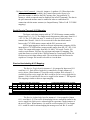
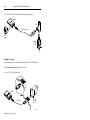
Schematic Diagrams:
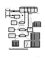
The electrical schematic diagram figure 1 shown on page 3, CDN366 is integrated
with an Allen Bradley (AB) SLC502. The AB SLC500 four-slot rack system contains a
rack power supply (1747-P1), a PLC processor on slot 0 (1747-L524), and a DeviceNet
scanner module on slot 1 (1747-SDN), an 8 points input module on slot 2 (1746-IV8),
and an 8 points output module on slot 3 (1747-OB8). (For further hardware and software
configurations, please visit Allen Bradley website at http://www.ab.com/ )
The 24vdc regulated power supply is powered the network BUS-(0vdc) and
BUS+(24vdc) on DIP790 board. DIP790 is a DeviceNet distribution board with 1-inline
& 6-outline connections. The DIP790 is connected to an AB 1747 DeviceNet scanner
module, which is tapped into the DeviceNet network. Based upon Open DeviceNet
Vendor Association, Inc. (ODVA) specification, the operational voltage ranges from
11~25 vdc. The nominal voltage is 24 vdc. (For more information on specifications, visit
ODVA home page at www.odva.org.)
The AB 1747-PIC is a communication interface module, which uses RSLogic500
software to interface with a PC. RSLogic500 is a window based ladder logic software
program. RSLogic500 enables the user to upload/download and monitor PLC data.
The AB 1770-KFD is a communication interface module, which enables the user
to communicate between serial RS232 to DeviceNet network. The communication
enables the user to setup, configure and access DeviceNet network information using
RSLinx and RSNetWorx software.
5
Allen Bradley SLC500 4 Slot Rack, 1746-A4
N
120VAC
Slot 1
SLC502
DeviceNet
PLC CPU
Scanner
24vdc output
Fuse 3A
1747-P1
120/240VAC
1747-L524 1747-SDN
Neutral
Comm.
Slot 2
Slot 3
8 pt. Input 8 pt.Output
module
module
1746-IV8
1746-OB8
Comm.
GND
DeviceNet network
24VDC Power Supply
Fuse 1A
Fuse 6A
+
120VAC
24VDC
-GND
PC Interface
To PC RS232 25
Module
Pin Serial Interface
1747-PIC
For Used with
RS232-PLC
RSLogic Prog.
RS232 serial
communication
to pin 5 DeviceNet connector
Input
Slot 0
to pin 1 DeviceNet connector
L
Power Sup.
PS to DeviceNet Dist.
Pin
Color
1
black
3
clear
Shield (Drain)
5
red
BUS+ (24vdc)
Description
BUS-
(0vdc)
PC Interface Mod.
To PC RS232 9 pin
Serial Interface For
1770-KFD
DIP790 Device
Used with RSLinx,
RS232-DeviceNet
Net Dist. Board
& RSNetWorx Prog.
Terminal Connector
DeviceNet
9 pin DIN RS232 Serial
Gateway Module
Pin
Color
Description
Interface to Barcode
CDN366
1
black
V- (BUS-)
Reader, Scanner
RS232-DeviceNet
2
blue
data low (CAN L)
3
clear
shield (Drain)
4
white
data high (CAN H)
5
red
V+ (BUS+)
Pin
Color
Description
1
clear
shield (Drain)
2
red
V+ (BUS+)
3
black
V- (BUS-)
4
white
data high (CAN H)
5
blue
data low (CAN L)
Weigh Scale or etc.
RS232 Pin Layout
Pin Func. Pin Func.
RXD
7
RTS
3
TXD
8
CTS
5
GND
2
Pin 1,4,6,9 are unused
DeviceNet
Male Connector
4
3
5
1
2
DeviceNet Connector
Figure 1. CDN366 Integrate with Allen Bradley SLC500
6
CDN366 Setup & Configurations:
Prior to the setup and configuration of the CDN366 device, the PLC hardware
(power supply, CPU, DeviceNet scanner, I/O modules), software (RSLinx, RSNetWorx
& RSLogic500) and interface modules must be setup and configured first. (For further
information on setup and configuration of the Allen Bradley PLC controller, please visit
www.ab.com)
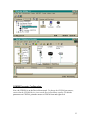
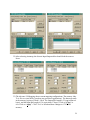
In this particular example, the hardware and software were setup and configured
based upon page 1 listing. The figures below demonstrate that the RSNLinx and
RSNetWorx are running. The DeviceNet scanner module scanned the network and found
node 00 (master DeviceNet scanner) and node 03 (slave interface module). It is
recommended to setup the DeviceNet master scanner module to MAC-ID 00. The
maximum number of nodes on the DeviceNet network is 64, with a MAC-ID ranges of
00~63.
7
Register Electronic Data Sheet (EDS) File:
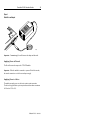
In order to integrate the CDN366 to DeviceNet network, the CDN366 must be set
up and configured first. CDN366 must be disconnected from the DeviceNet network
before configuring the node address and baud rate. Set the DeviceNet baud rate to match
with the network baud rate. Set the Mac ID to an unused node address. The example
below shows that the CDN366 was set at Mac ID 01 (MSD=0, LSD=1), and DeviceNet
network baud rate is at 125Kb.
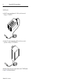
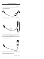
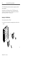
RS-232 9 pin DIN male connector
Connect to serial perhiphial
Micro-style male connector
5 pin to DeviceNet network
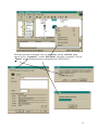
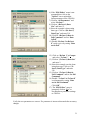
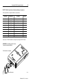
Connect the CDN366 to the DeviceNet network and click on the “network scan” (Online
icon). The DeviceNet master will scan the network. The CDN366 is not registered.
Therefore, RSLinx and RSNetworx do not recognize the device.
Online
8
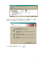
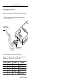
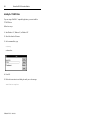
In order to register the CDN366 on RSNetWorx, click on “Tools” and select “EDS
Wizard”. Click on “Next>” and the “Options” menu is prompted.
Select “Register an EDS file(s)” and click on “Next>”
9
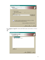
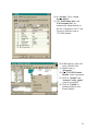
Select “Register a single file” and enter the EDS file name on the white box. Click on
“Next>”
10
The “EDS File Installation Test Results” menu is prompted, click on “Next>”. The
“Change Graphic Image” menu is prompted. Select CDN366 and click on “Change
icon”.
Select another icon to replace current CDN366 icon. Click “OK” to exit “Change Icon”
menu. After it is changed to a new icon, click on “Next>”.
11
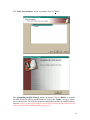
The “Final Task Summary” menu is prompted, click on “Next>”
The “Completing the EDS Wizard” menu is prompted. Click on “Finish” to complete
the EDS Wizard. On RSLinx and RSNetWorx, click on the “Online” icon to re-scan or
browse the network. The CDN366 should be identified on the RSLinx and RSNetWorx
network. If after registering the EDS file, the CDN366 is unrecognized on the DeviceNet
network (see the Troubleshooting Guide on page 35).
12
CDN366 Parameter Configuration:
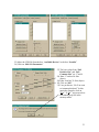
Now, the CDN366 is on the DeviceNet network. To change the CDN366 parameters,
ensure that the CDN366 device is not on the DeviceNet master scanlist. To edit the
parameters on CDN366, point the mouse to CDN366 icon and right click.
13
When the sub-menu is prompted, click on “Properties” and the “CDN366” menu
appears. Select “Parameters”, and the “EDS Editor” sub-menu is prompted. Click on
“Upload”, and the default parameters will upload from CDN366 device.
14
Download parameters to device
Upload parameters from device
Monitor Parameters
Help for the selected parameter
Restore default parameters
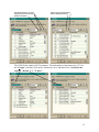
The CDN366 has eight (8) Rx/Tx instances. The total number of parameters are 155. On
the “Groups” selection, click on the “down arrow key” and then select “Serial Stream
Object”, “Rx Inst 1” or “Tx Inst 1”.
15
Change Parameter Setting Using RSNetWorx:
The CDN366 must be offline (not on Scanlist) to change any parameters. Some of
the parameters cannot be change, but can be read (see CDN366 DeviceNet Specifications
for details). Before making the parameter change, always upload the current parameters
from the CDN366 device.
1) In the “Parameters” menu, double click on the parameter, and enter the new
value. Then press “Enter” to accept the new value.
2) Click on “Apply” and click on “Yes” to download new changes to CDN366.
Another method for changing the parameters on CDN366 is using RSNetWorx.
1) Point mouse to CDN366 icon and right click. The sub menu is prompted.
2) Click on “Class Instance Editor”, and the “WARNING!” alert menu is
prompted.
3) Click on “Yes” to access the class instance editor menu.
Service Code: Used to verify or
set new/current parameters for a
single or a group of attributes.
Object Address: Enters a
particular class, instance and
attribute to verify or change
parameter setting.
Set data in decimal or
hexadecimal value.
16
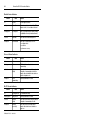
Serial Stream Object Parameters (Class Code 64):
1) Baud Rate: The serial channel RS232 baud rate ranges from 300 ~ 57600 bits/sec.
The acceptable baud rate are 300, 1200, 2400, 4800, 9600, 19200, 38400, and
57600. The baud rate should be set to match the serial connection.
2) Data Bits: The number of data bits can be selected at 7 or 8 bits. The data bits
should be set to match the serial connection.
3) Parity: The parity bit can be selected at None, Odd, Even, Mark or Space. The
parity bit should be set to match the serial connection.
None = no parity
Odd = parity bit =1, if there are odd number of one in data size
Even = parity bit =1, if there are even number of ones data size.
Mark = parity bit is 1 always
Space = parity bit is 0 always
In most applications, parity bit is set at None (no parity).
4) Stop Bits: The stop bits can be selected at 1 or 2. Each data byte (character)
transmitted in a sequence is followed by 1 or 2 extra zero bits. The extra “0” is
marked at the end of a character transmission. In most applications, the stop bit is
set at 1. The stop bits should be set to match the serial connection.
1 = Each data byte (character) transmit is followed by one zero (0).
2 = Each data byte (character) transmit is followed by two zeros (0).
5) Flow Control: The flow control can be set at 0, 1, or 2. When flow control is set
to 1, the X-Off (CTRL S) will force the CDN366’s transmit function to block.
The transmitted characters are stored in the FIFO buffer until transmission is reenable by sending the X-On (CTRL Q) character to the CDN366. When the
receive FIFO buffer is full, the X-Off character is transmitted to the RS232
interface. The X-On/ X-Off flow control characters are extracted from the data
stream. Therefore, this setting is unsuitable for making binary data transmissions.
When flow control is set to 2, the RTS (pin 7) and CTS (pin 8) control signals are
enabled. The data is transmitted only when the CTS signal asserts a high/low
voltage. When the receive FIFO buffer is not full, the RTS signal is asserted to
allow data reception.
0 = No flow control
1 = X-On/X-Off flow control (software flow control)
2 = CTS / RTS flow control (hardware flow control)
In most applications, the flow control is set to 0 (no flow control).
17
6) Delimiter Mode: The delimiter is used to
determine when the a complete packet is
received from the RS232 side (see
DeviceNet for further info.). There are three
functions in delimiter mode: List, Timeout
and Length.
List – select “List” when using the injunction with Pre and Post Short String data
type format. The Pre/Post delimiters can be set in ASCII characters. Pre-delimiter
is a character or list of characters (short string data type range 1~256 bytes) that
trigger CDN366 to read the beginning of a data packet. Post-delimiter is a
character or list of characters (short string data type range 1~256 bytes) that
trigger CDN366 to read the end of a data packet.
Example: The data packet looks like this => [STX][Barcode data][ETX][CR]
STX (start of text) =ASCII 0x02, ETX (end of text) = ASCII 0x03,
CR (carriage return) = ASCII 0x13
STX= Pre-delimiter (Class=64, Instance=1, Attribute=11)
ETX + CR = Post-delimiter (Class=64, Instance=1, Attribute=12)
Setting Pre/Post delimiters: All values are in ASCII unit.
Pre-delimiter (Class=64, Instance=1, Attribute=11) = 01 02
Pos-delimiter (Class=64, Instance=1, Attribute=12) = 02 03 13
First byte is defined as bytes length in ASCII characters. The 01 is equivalent to 1
byte length, which is in Pre-Delimiter. The 02 is equivalent to 2 bytes length
which is that set in Post-Delimiter.
Timeout – When Timeout Delimiter is enabled, the value is set at Packet Timeout
(Class=64, Instance=1, Attribute=13), which will delay the time to determine
when a package is completed. The Packet Timeout value ranges from 1~255msec.
A poll response message is sent, if either the Packet Length or Post Delimiter is
not received within the time specified in the Packet Timeout.
Packet Timeout – Specifies the amount of time in milliseconds (1~255msec)
between bytes that CDN366 uses to determine when the data packet is complete.
18
Length – When a value (byte range from 1~255) is set in the Packet Length,
(Class=64, Instance=1, Attribute=14) the data packet is fixed based upon the
Packet Length. As the data packet receives from a poll response, the data packet is
complete as number of bytes sent is equal to the byte value set in Packet Length.
Packet Length – Specifies the number of bytes (1~255 bytes) to wait for before
determining the data packet is complete.
7) Serial Status: The serial status indicates
whether the serial Receive/Transfer on RS232
has errors. When an error has occurred
in the serial status, a bit is set for the error.
Set any of these bits to zero, and it will clear
the particular error.
8) Poll Produce Size: This attribute can be accessed as read only. The produce size
is defined as the number of Rx data bytes plus two handshaking bytes. One
handshaking byte is for Transmit Acknowledge, which confirms the data
transmitted in instances 1 to 8. Bit 0 is set for transmit acknowledge in Instance 1.
Bit 1 is set for transmit acknowledge in Instance 2 and etc. The other handshaking
byte is for the Receive Toggle, which toggle instances 1 to 8. Bit 0 is set for
receive toggling in Instance 1. Bit 1 is set for receive toggling in Instance 2 and so
on (see Serial Receive/Transmit & I/O Mapping section). When Poll I/O
Connection is established with Allen Bradley 1747-SDN DeviceNet master
scanner, the produce size number of bytes will map into discrete Input data
memory or M file table.
9) Poll Consume Size: This attribute can be accessed as read only. When
establishing a short string data type I/O connection, the produce size is defined as
the number of Tx data bytes plus two handshaking bytes. One handshaking byte is
for Transmit Toggle for instances 1~8. The other one handshaking byte is for
Receive Acknowledge for instances 1~8, (see Serial Receive/Transmit & I/O
Mapping section). When Poll I/O Connection is established with Allen Bradley
1747-SDN DeviceNet master scanner, the consume size bytes will map into
discrete Output data memory or M file table.
19
Serial Receive Object Parameters (Class Code 65):
There are eight identical receive (Rx) instance parameters which can be set in CDN366.
This section will review one of the eight receive instance parameters. These parameters
can easily be changed using RSNetWorx. When using RSNetWorx to upload the
parameters, first go to “Groups” and select “Rx Inst 1”.
10) Receive Toggle: This parameter is
read only. When new data has been
received, bit 0 is toggle (see Receive
Handshaking & I/O Mapping).
11) Receive Acknowledge: The value
in this parameter ranges from 0~1 bit.
In the poll response, this value must
match with the Receive Toggle bit to
receive new serial data on the
DeviceNet. The Sync Enabled attribute
must be enable when using this
attribute (see Receive Handshaking&
I/O Mapping).
12) Receive Mode: Bits 3~7 are
unused (label Xs). When a bits 0~2 are
set to 1, their function is enabled.
bit 7
unused
Receive Mode (class=65, instance=1, attribute=6)
bit 6
bit 5
bit 4
bit 3
bit 2
bit 1
unused
unused
unused
unused Use Post Use Pre
bit 0
Use Data
Use Data (bit 0): Normally, this parameter bit is set to 1. When it is enabled, the
packet data is extracted to transmit to DeviceNet.
Use Pre-String (bit 1): When this parameter bit is set to 1, the pre-string ASCII
characters (bytes) will be removed before the PLC receives data from DeviceNet.
Pre-string characters are the ASCII characters found before the serial data.
Use Post-String (bit 2): When this parameter bit is set to 1, the post-string ASCII
characters (bytes) will be removed before the PLC receives data from DeviceNet.
Post-string characters are the serial ASCII characters found after the data.
20
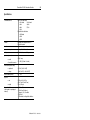
13) Date Type: When 194 or 198 is entered for Data Type (class=65, instance=1,
attribute=9), then one byte will be allocated for Data Size (class=65, instance=1,
attribute=10). When 195 or 199 is entered for Data Type, then two bytes will be
allocated for Data Size. When 202 is entered for Data Type, then four bytes will
be allocated for Data Size.
Decimal
194
195
198
199
202
218
Hex.
0xC2
0xC3
0xC6
0xC7
0xCA
0xDA
Date Size (byte)
Value Range
Data Type
1
-128 ~ 127
SINT (signed 8-bit integer)
2
-32768 ~ 32767
INT (signed 16-bit integer)
1
0 ~ 255
USINT (unsigned 8-bit integer)
2
0 ~ 65535
UINT (unsigned 16-bit integer)
+1.175E-38 ~ +3.4028E+38
4
REAL (32-bit floating point value)
Short_String
Set by data size attribute, Max. 255 bytes
The Short-String data type is used in most applications. Short-String data type is
used to transfer serial data in ASCII format.
Example: When a barcode reader sent data, “12345678” to CDN366, CDN366
converted the numbers to DeviceNet signal and send it to PLC. In the PLC
memory Input I/O table or M-file (must copy to N-integer to be able to view), the
data received is listed as ASCII format “812345678” or Hex format “38 31 32 33
34 35 36 37 38”.
14) Data Size: The data size (class=65, instance=1, attribute=10) is settable only if
the Data Type (class=65, instance=1, attribute=9) is Short-String. The maximum
number of ASCII characters (bytes) is 256.
15) Width: This attribute is not applicable for Short-String data type. The maximum
settable width (class=65, instance=1, attribute=11) for a real or integer data type
is 16.
Example: In order to receive a real value as “-1.2345E-16”, the width should be
set to at least 11. When the width is set to 7, the received real value is “-1.2345”.
16) Conversion: The conversion (class=65, instance=1, attribute=13) is valid only
when the Data Type is an integer type. The conversion can convert from
hexadecimal (X) to decimal (d) or vice versa. The attribute is settable to
“D”=0x44 (Hex.) for decimal and “X”=0x58 (Hex.) for hexadecimal.
17) Data In Poll Response: When data in the poll response is set to 1 (enable), the
Receive Data packet (bytes) of a particular instance is added in the CDN366’s
Poll Response. Any particular Rx instances, which are unused, must be disabled.
The data in the poll response attribute must be enabled to establish an I/O
connection with the master scanner (see Input Memory Table of A-B 1747-SDN
mapping).
21
18) Enable: When the enable search receive string is set to 1, the current instance will
be used to process the incoming receive message (packet) to extract the data
specified in Data Type. This attribute should be disabled for all unused instances.
19) Sync Enabled: When sync enable is set to 1, the CDN366 will not respond with
new serial data until the value in the Receive Acknowledge bit has been toggled.
Enabling this attribute ensures that the master scanner module does not miss data
between polls.
Serial Transmit Object Parameters (Class Code 66):
There are eight replicate independent transmit (Tx) instances, which can be set in
CDN366. This section is using RSNetWorx to review one of eight transmit instances in
CDN366.
20) Transmit Toggle: The transmit
toggle byte for 8 instances are mapped
to 1747-SDN Output I/O table.
Instance 1 transmit toggle is bit 0. Bit
0, one of the eight bits, which toggles
between 0 & 1. When bit 0 is toggled,
the data is sent out to RS232 side of
CDN366 (see Transmit Handshaking &
I/O Mapping).
21) Transmit Acknowledge: The
transmit acknowledge byte for 8
instances are mapped to 1747-SDN
Input I/O table. The information can be
accessed as read only. Instance 1
transmit acknowledge is bit 0. Bit 0,
one of the eight bits, which toggles
between 0 & 1. When bit 0 is toggled,
data has been transmitted (see Transmit
Handshaking & I/O Mapping).
Note that Tx Ack., Tx toggle, Rx Ack., and Rx Toggle are attributes used in the poll
command and poll response to control the serial/DeviceNet data transfer and do not need
to be set explicitly as part of the CDN366 setup.
22
22) Transmit Mode: (class=66, instance=1,
attribute=6) Bits 5~7 are unused. The transmit
mode is used for transmitting the data in
conjunction with strings before and/or after data.
The String1 (class=66, instance=1, attribute=7) is
a list of ASCII characters (bytes) to be transmitted.
The String2 (class=66, instance=1, attribute=8) is
a list of ASCII characters (bytes) to be transmitted.
Example: Set String1 to start of text (STX) and String2 to end of text (ETX) with
carriage return (CR).
In the ASCII table, STX is 0x01, ETX is 0x03 and CR is 0x13 in hex.
Format: String1 = [length in characters (bytes)][char.1] [char.2] … [char.9]
Format: String2 = [length in characters (bytes)][char.1] [char.2] … [char.9]
String1 and String2 each can be set a at max. of nine (9) ASCII char. (bytes).
String1 = STX = 01 02 (01 is one char. length, 02 is STX in ASCII).
String2 = ETX + CR = 02 03 13 (02 is two char. length, 03 is ETX & 13 is
CR in ASCII).
Example: Set String1 Before data and String2 After data.
Format: [String1 Before][String2 Before][Data][String1 After][String2 After]
[String1 Before] [Data] [String2 After] = [STX] [Data] [ETX + CR]
23) Data Type: When 194 or 198 is entered for Data Type (class=66, instance=1,
attribute=9), one byte will be allocated for Data Size (class=66, instance=1,
attribute=10). When 195 or 199 is entered for Data Type, two bytes will be
allocated for Data Size. When 202 is entered for Data Type, four bytes will be
allocated for Data Size.
23
Decimal
194
195
198
199
202
218
Hex.
0xC2
0xC3
0xC6
0xC7
0xCA
0xDA
Date Size (byte)
Value Range
Data Type
1
-128 ~ 127
SINT (signed 8-bit integer)
2
-32768 ~ 32767
INT (signed 16-bit integer)
1
0 ~ 255
USINT (unsigned 8-bit integer)
2
0 ~ 65535
UINT (unsigned 16-bit integer)
+1.175E-38 ~ +3.4028E+38
4
REAL (32-bit floating point value)
Short_String
Set by data size attribute, Max. 255 bytes
24) Data Size: The data size (class=66, instance=1, attribute=10) is settable only if
the Data Type (class=66, instance=1, attribute=9) is Short-String.
25) Width: This attribute is not applicable for Short-String data type. When Width
value (bytes) is set greater than the size (bytes) of the converted value, the Tx
Leading Zeros (class=66, instance=1, attribute=11) bit will pad 0’s in front of the
data (see examples below).
Data
4.75
4.75
4.75
4.75
4.75
Width
8
8
8
8
8
Precision Leading Zeros Result
2
enabled
00004.75
3
enabled
0004.750
2
disabled
4.75
4
disabled
4.7500
1
enabled
000004.8
26) Precision: (class=66, instance=1, attribute=12) Specifies the number of places
after the decimal point that are transmitted. This attribute applies only to the Real
data type. The maximum number of decimal points is six (6).
27) Conversion: (class=66, instance=1, attribute=13) Bits 1~5 are unused. When bit
0 is set to 1, the transmitted integer value will be converted to hexadecimal. When
bit 0 is set to 0, the transmitted integer value will be converted to decimal. Bit 7 is
set to 1 to enable Leading Zeros. When Leading Zero is enabled, the zeros are
padded in front of the data.
Conversion (class=66, instance=1, attribute=13)
bit 7
bit 6
bit 5
bit 4
bit 3
bit 2
bit 1
Leading
unused unused unused unused unused unused
Zero
1
1
0
0
bit 0
Hex
1
0
1
0
Conversion Options
Hex.
Decimal
129
0x81
128
0x80
1
0x01
0
0x00
24
28) Data in Poll Command: (class=66, instance=1, attribute=15) When data in the
poll command is set to 1 (enabled), the Transmit Data packet (bytes) of a
particular instance is added to the Poll Consume Size. Any particular Tx
instances, which are unused must be disabled (Not in Poll Command.) The data in
the poll command attribute must be enabled in order to establish an I/O
connection with the master scanner (see Output Memory Table of A-B 1747-SDN
mapping.)
Serial Receive/Transmit & I/O Mapping:
The Input words data memory table in 1747-SDN master scanner module
ranges from I:1.0 ~ I:1.31. The Output words data memory table range from O:1.0
~ O:1.31. The 1747-SDN can store 31 words or 62 bytes of serial receive or
transmit data. Words I:1.0 & O:1.0 are reserved for the data block transfer
between the 1747-SDN master scanner and the PLC processor unit.
M-File input mapping is similar to discrete input memory mapping. M-file
input table in 1747-SDN master scanner module ranges from M1:1.0 ~ M1:1.149
words. The output table ranges from MO:1.0~MO:1.149 words. Total is 150
words or equivalent to 300 bytes for each input and output I/O mapping. The
serial data sent or received by the CDN366 cannot be viewed on the M-file. Mfile does not exist in data memory table. The serial data in the M-file must be
copied to a N integer file in order to be able to view the data.
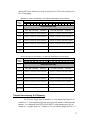
Receive Handshaking & I/O Mapping:
The Receive Toggle byte for instances 1~8 is mapped in Input word I:1.1
word bits 8~15. Each receive toggle bit is controlled by a single instance of
receive object. When Instance 1 is used for serial reception, bit 8 at Input I:1.1
would be used for receive toggle bit. Bit 9 would be use for receive toggle bit for
instance 2. Bit 14 would be use for receive toggle bit for instance 7. The input MFile mapping is similar to discrete input mapping.
Receive Toggle bits 8~15 (1 byte)
Transmit Acknolwedge bits 0~7 (1 byte)
15
14
13
12
11
10
9
8
7
6
5
4
3
2
1
0
I:1.1 Inst. 8 Inst. 7 Inst. 6 Inst. 5 Inst. 4 Inst. 3 Inst. 2 Inst. 1 Inst. 8 Inst. 7 Inst. 6 Inst. 5 Inst. 4 Inst. 3 Inst. 2 Inst. 1
Receive Acknowledge bits 8~15 (1 byte)
Transmit Toggle bits 0~7 (1 byte)
15
14
13
12
11
10
9
8
7
6
5
4
3
2
1
0
O:1.1 Inst. 8 Inst. 7 Inst. 6 Inst. 5 Inst. 4 Inst. 3 Inst. 2 Inst. 1 Inst. 8 Inst. 7 Inst. 6 Inst. 5 Inst. 4 Inst. 3 Inst. 2 Inst. 1
The Receive Acknowledge byte for instances 1~8 are mapped in Output
O:1.1 word bits 8~15. The receive acknowledge bits are configured similar to the
receive toggle bits. Each receive acknowledge bit represents a single instance of
the receive object. When Instance 4 is used for serial reception, bit 11 at Output
O:1.1 would be used for acknowledging the message received. Bit 11 would
25
toggle from 0 to 1. The output M-File mapping is similar to discrete inputs
mapping.
When the short-string data type is used in instance 1, the Receive Data
Size located in Input I:1.2 word bits 0~7. The Receive Data Size indicates the
number of ASCII data bytes received from the RS232 serial connection by the
CDN366. When RS232 serial data is received, the CDN366 counts the total
ASCII data characters (bytes) in the message packet and places the value in
starting at word I:1.2, bits 0~7. The ASCII characters (bytes) data received by the
CDN366 are mapped onto words I:1.2 ~ I:1.31 (depending on the data size.) Each
ASCII character is equivalent to one byte. Two bytes are equivalent to one word.
The orders of the characters are mapped from right (least significant byte) to left
(most significant byte) (see Input Memory and Input M-File Tables of Allen
Bradley 1747-SDN).
To use both the Receive Toggle & Receive Acknowledge bits to control
serial messages received by the CDN366 to the PLC input memory, the “Sync
Enable” (class=65, instance=1, attribute=17) attribute must be “On”. The “Sync
On” requires the PLC ladder logic to control the handshaking bits to acknowledge
newly received data before subsequent data can be received. The following
discusses the “Rx Instance 1” reception.
1) Bit 0s are set to 0 at initial setting for Rx Instance 1 Receive Toggle and
Receive Acknowledge. When data is received on the RS232 serial, the
Receive Toggle bit 8 in input I:1.1 (Rx instance 1) is toggled from 0 to 1.
The first byte of the received data is the data size length, which is stored in
Input I:1.2 bits 0~7. The data is stored in Input I:1.2 bits 8~15 and so on
(see Input Memory Table of Allen Bradley)
2) To acknowledge that data was received by the PLC, the Receive
Acknowledge bit 8 on Output O:1:1 must toggle from 0 to 1. To do this,
the PLC must use ladder logic to copy Receive Toggle bit 8 to Receive
Acknowledge bit 8. As long as the Receive Toggle and Receive
Acknowledge bits are the same, the CDN366 can update with the next
serial message.
3) When the Receive Acknowledge bit 8 is not toggled to acknowledge that
new data is received, the CDN366 will continue to hold newer serial data
in the Rx FIFO until the buffer overflows.
When the “Sync Enable” is disabled, the Receive Acknowledge bits 8~15 serve no
purpose, even when they are toggled. The new data sent from RS232 serial to
PLC input memory cannot be controlled by Receive Acknowledge bits although a
value must be present. Receive Toggle bit 8 (Rx Instance 1) is toggled for every
new message it receives. The message data will be stored in the same PLC Input
memory location until the new message is received and the existing message is
replaced.
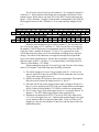
Example: The table below shows a short string data type with two receive
instances that are mapped into discrete/M-file Inputs I/O. Each instance is
26
allocated for three characters (bytes) for serial receive. The total is ten bytes for
PLC I/O mapping.
Input Memory Table of Allen Bradley 1747-SDN DeviceNet Master Scanner Module
1 Word Addressing I/O
Data
1 byte = 8 bits
1 byte = 8 bits
Memory
15 14 13 12 11 10
9
8
7
6
5
4
3
2
1
Table
0
Reserved Read-Only
I:1.0
I:1.1
Receive (Rx) Toggle: bits 8~15
Inst1=bit8, Inst2=bit9, .., Inst8=bit15
Transmit (Tx) Acknowledge: bits 0~7
Inst1=bit0, Inst2=bit1, .., Inst8=bit7
I:1.2
Instance 1: Receive ASCII Character 1
Instance 1: Receive Data Size (length)
I:1.3
Instance 1: Receive ASCII Character 3
Instance 1: Receive ASCII Character 2
I:1.4
Instance 2: Receive ASCII Character 1
Instance 2: Receive Data Size (length)
I:1.5
Instance 2: Receive ASCII Character 3
Instance 2: Receive ASCII Character 2
:
:
:
:
I:1.31
:
:
M-File Input Table of Allen Bradley 1747-SDN DeviceNet Master Scanner Module
1 Word Addressing I/O
Data
1 byte = 8 bits
1 byte = 8 bits
Memory
15 14 13 12 11 10
9
8
7
6
5
4
3
2
1
Table
0
Reserved Read-Only
I:1.0
I:1.1
Receive (Rx) Toggle: bits 8~15
Inst1=bit8, Inst2=bit9, .., Inst8=bit15
Transmit (Tx) Acknowledge: bits 0~7
Inst1=bit0, Inst2=bit1, .., Inst8=bit7
M1:1.0
Instance 1: Receive ASCII Character 1
Instance 1: Receive Data Size (length)
M1:1.1
Instance 1: Receive ASCII Character 2
Instance 1: Receive ASCII Character 3
M1:1.2
Instance 2: Receive ASCII Character 1
Instance 2: Receive Data Size (length)
M1:1.3
Instance 2: Receive ASCII Character 2
Instance 2: Receive ASCII Character 3
:
:
:
:
M1:1.149
:
:
Transmit Handshaking & I/O Mapping:
The Transmit Toggle byte for instances 1~8 are mapped in Output O:1.1
word bits 0~7. Each transmit toggle bit represents each instance. When transmit
Instance 1 is completed from DeviceNet to RS232 serial transmission, bit 0 at
Output O:1.1 toggles from 0 to 1. Instances 2~8 are similarly mapped to bits 1~7.
27
The Transmit Acknowledge byte for instances 1~8 is mapped in Input I:1.1
word bits 0~7. Each transmit acknowledge bit corresponds to an instance of the
transmit object. When data is sent from PLC to the RS232 serial connection, the
Input I:1.1 bit 0 (Instance 1) toggles when the data is transmitted by the CDN366.
Bit 0 toggles between 0 and 1. Instances 2~8 are setup similarly mapped to bits
1~7.
Receive Toggle bits 8~15 (1 byte)
Transmit Acknolwedge bits 0~7 (1 byte)
15
14
13
12
11
10
9
8
7
6
5
4
3
2
1
0
I:1.1 Inst. 8 Inst. 7 Inst. 6 Inst. 5 Inst. 4 Inst. 3 Inst. 2 Inst. 1 Inst. 8 Inst. 7 Inst. 6 Inst. 5 Inst. 4 Inst. 3 Inst. 2 Inst. 1
Receive Acknowledge bits 8~15 (1 byte)
Transmit Toggle bits 0~7 (1 byte)
15
14
13
12
11
10
9
8
7
6
5
4
3
2
1
0
O:1.1 Inst. 8 Inst. 7 Inst. 6 Inst. 5 Inst. 4 Inst. 3 Inst. 2 Inst. 1 Inst. 8 Inst. 7 Inst. 6 Inst. 5 Inst. 4 Inst. 3 Inst. 2 Inst. 1
When the short string data type is used for instance 1, the Transmit Data
Size is located in Output O:1.2 word bits 0~7. The Transmit Data Size indicates
the number of ASCII data bytes to be transmitted from DeviceNet to the RS232
serial side. Enter a number in Output O:1.2, bits 0~7 to represent how many
ASCII data characters (bytes) are to be transmitted (excluding the pre and post
strings). The orders of the characters are mapped from right (least significant
byte) to left (most significant byte). For the data size number of bytes, the first
character starts word O:1.2 at bits 0~7 (see Output Memory and Output M-File
Tables of Allen Bradley 1747-SDN).
When sending data using the Transmit Toggle and Transmit Acknowledge
(bit 0 for Tx Instance 1) the following steps should be performed.
1) The initial setting for Transmit Toggle Output word O:1.1, bit 0 is 0. In
order to send ASCII data out to the RS232 serial connection, the Transmit
Toggle bit 0 must toggle from 0 to 1.
2) Specify the number of characters (bytes) to be transmitted. This transmit
data size must be entered in Output word O:1.2, bits 0~7.
3) Enter the ASCII data in the Output memory table, starting in Word O:1.1,
bits 8~15 to be transferred to RS232 side (see Output Memory and Output
M-File Tables of Allen Bradley 1747-SDN for characters arrangement).
4) The Transmit Toggle bit 0 must toggle from 0 to 1 to transmit data for Tx
Instance 1. The PLC ladder logic program must toggle this bit.
5) When data is transmitted to RS232, Transmit Acknowledge Input word
I:1.1, bit 0 will toggle from 0 to 1. Indicate that transmit toggle can toggle
to 0 to send new data. For numerical data (Real, Usint, etc.) there is no
length byte, only the fixed number of data-size, and data bytes follow the
handshaking bytes.
28
Example: The table below shows a short string data type with two transmit instances that
are mapped into discrete/M-file Outputs I/O. Each instance is allocated for
three characters (bytes) for serial transmit. The total is ten bytes for the PLC
I/O mapping.
Output Memory Table of Allen Bradley 1747-SDN DeviceNet Master Scanner Module
1 Word Addressing I/O
Data
1 byte = 8 bits
1 byte = 8 bits
Memory
15 14 13 12 11 10
9
8
7
6
5
4
3
2
1
Table
0
Reserved Read-Only
O:1.0
O:1.1
Receive (Rx) Acknowledge: bits 0~7
Inst1=bit8, Inst2=bit9, .., Inst8=bit15
Transmit (Tx) Toggle: bits 0~7
Inst1=bit0, Inst2=bit1, .., Inst8=bit7
O:1.2
Instance 1: Transmit ASCII Character 1
Instance 1: Transmit Data Size (length)
O:1.3
Instance 1: Transmit ASCII Character 3
Instance 1: Transmit ASCII Character 2
O:1.4
Instance 2: Transmit ASCII Character 1
Instance 2: Transmit Data Size (length)
O:1.5
Instance 2: Transmit ASCII Character 3
Instance 2: Transmit ASCII Character 2
:
:
:
:
O:1.31
:
:
M-File Output Table of Allen Bradley 1747-SDN DeviceNet Master Scanner Module
1 Word Addressing I/O
Data
1 byte = 8 bits
1 byte = 8 bits
Memory
15 14 13 12 11 10
9
8
7
6
5
4
3
2
1
Table
0
Reserved Read-Only
O:1.0
O:1.1
Receive (Rx) Acknowledge: bits 8~15
Inst1=bit8, Inst2=bit9, .., Inst8=bit15
Transmit (Tx) Toggle: bits 8~15
Inst1=bit0, Inst2=bit1, .., Inst8=bit7
MO:0.0
Instance 1: Transmit ASCII Character 1
Instance 1: Transmit Data Size (length)
MO:0.1
Instance 1: Transmit ASCII Character 2
Instance 1: Transmit ASCII Character 3
MO:0.2
Instance 2: Transmit ASCII Character 1
Instance 2: Transmit Data Size (length)
MO:0.3
Instance 2: Transmit ASCII Character 2
Instance 2: Transmit ASCII Character 3
:
:
:
:
MO:0.149
:
:
29
Mapping the Poll I/O Connection to AB-1747-SDN:
Before using the RSNetWorx to map the poll I/O connection to 1747-SDN DeviceNet
master scanner, the total number of bytes of the Poll Produce Size & Poll Consume Size
must be determined. The format of the poll response and poll command are listed below:
Poll Response: [TxAck bits1~8][RxToggle bits1~8][Rx Data Inst.1] …[Rx Data Inst.8]
Poll Command: [TxToggle bits1~8][RxAck bits1~8][Tx Data Inst.1] …[Tx Data Inst.8]
The poll produce size is the size (bytes) of the poll response and the poll consume size is
based upon the size (bytes) of the poll command. The data DeviceNet packets for each
can have as many as eight data instances. The poll produce size and the poll consume size
are each based on the number of instances and data size used in each Rx/Tx packet. The
data size for Short String data type for each serial receive/transmit is:
Data Size (bytes) = 1 + number of ASCII character to receive.
The constant “1” is one byte reserve for the short string data size length. So if 3 bytes of
short-string data are used, the data size should be set to 4 bytes to include the length byte.
Example: Using RSNetWorx for DeviceNet to map CDN366 for receiving 14 bytes of
barcode data and transmitting 1 byte for data confirmation. Typical in many
applications, CDN366 is setup to use only one instance.
Rx Instance 1 data size = 1 + 14 = 15 bytes
Tx Instance 1 data size = 1 + 1 = 2 bytes
For short string (poll response and poll command):
Consume size = 2 (handshaking) + 1 (length) + number of data byte (exclude delimiter)
For numeric (Real, usint, etc.):
Consume size = 2 (handshaking) + number of data byte (exclude delimiter)
1) In RSNetWorx,
right click on the
CDN366 icon.
2) Double click on
“Properties”
3) The menu
“CDN366”
should pop up.
4) Click on
“Parameters”
5) If the “EDS
Editor” prompts,
click on
“Upload”
30
6) If the “EDS Editor” menu is not
prompted then click on the
“Upload” icon to upload the
latest parameters to the CDN366.
7) Click on “All Parameters” and
select “Rx Inst 1”.
8) Click on “(Rx Inst-1) Data
Size” and enter 15.
9) Since the example is short-string
data type. Click on “(Rx Inst-1)
Data Type” and enter 218.
10) Click on “(Rx Inst-1) Data in
Poll Command” and set “Data
in Poll”.
11) Disable “Rx Inst-2 to Rx Inst8” serial receive by setting “Data
not in Poll”.
12) Click on “Rx Inst 1” in Groups:
and select “Tx Inst 1”.
13) Click on “(Tx Inst-1) Data Size”
and enter 2.
14) Since this example uses the shortstring data type. Click on “(Tx
Inst-1) Data Type” and enter
218.
15) Click on “(Tx Inst-1) Data in
Poll Command” and set “In Poll
Command”.
16) Disable “Tx Inst-2 to Tx Inst-8”
serial transmit by setting “Data
not in Poll Command”.
Click“OK”.
17) The “EDS Editor” menu is
prompted, click on “Yes” to
download new parameter settings
to CDN366.
Verify the new parameters are correct. If a parameter is incorrect then make the necessary
changes.
31
18) In “Groups:” select “Serial
Stream Object”
19) The “Poll Produce Size” and
“Poll Consume Size” are
automatically adjusted based on
the new configuration. The 17 and
4 bytes are needed to map to
1747-SDN module.
20) In RSNetWorx, right click
on the CDN366 icon.
21) Double click on
“Properties”
22) The “1747-SDN Scanner
Module” menu is prompted.
23) Click on “Scanlist” and
“Scanner Config. Applet”.
A menu is prompted.
24) Click on “Upload” to
upload parameters from
scanner module.
32
25) Move the CDN366 from the box “Available Devices” to the box “Scanlist”.
26) Click on “Edit I/O Parameters”
27) The byte values from “Poll
Produce Size” and “Poll
Consume Size” are 17 and 4.
28) Enter 17 on box Rx Size
(bytes).
29) Enter 4 on box Tx Size (bytes).
30) Click on “OK”.
31) User preference, “Do You want
to Automap this data?” In this
particular example, click on
“Yes”. If “No”, user must select
to manually map I/O in the
memory tables.
33
32) After selecting Automap, the discrete Input/Output tables should look the same as
above.
33) The Advance I/O Mapping shows current mapping configurations. The memory Map
To is Discrete (not M-file, based on user preference/applications). The data map starts
in the memory register of Word 1, Bit 0. The Output Bit Length is 32 (equivalent to 4
bytes), and the Input Bit Length is 136 (equivalent 17 bytes). Click on “Close” to
exit. Click on “Apply”. Click “Yes” to download these changes to 1747-SDN
memory.
34
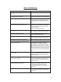
Basic Troubleshooting
Problem
Could be caused by
1) DeviceNet master scanner did not recognize the
device.
1) EDS file is not registered.
2) DeviceNet master scanner did not recognize the
device after loading the EDS file.
2) Device minor and major revisions do not match
EDS file. Verify EDS file minor & major revisions.
3) Device did not appear on the DeviceNet network.
3) Verify wiring connection & correct voltage. Verify
node address is not occupied by anther device.
Verify baud rate switch matches the network baud
rate.
4) After configuring the node address, the DeviceNet
master scanner did not recognize the device.
4) Disconnect the device before changing the node
address.Verify node address is not occuppied by
another device. Verify node address is setup by
software or hardware.
Verify DeviceNet network baud rate.
5) Net LED indicator light is flashing red.
5) Device is removed from the Scanlist or network.
Recycle the device power to reset the NET LED.
6) Net LED indicator light is solid red.
6) Verify node address is not occuppied by other
device. DeviceNet network failure.
7) Net LED indicator light is off.
7) Verify DeviceNet network baud rate.
Verify DeviceNet network wiring and connection.
8) MOD LED indicator light is flashing/solid red.
8) Device has failed. If necessary, replace the device.
9) RX LED indicator light does not flash green when
data is sent to the device.
9) If Sync is enabled, verify receive toggle & receive
acknowledge bits are toggled. If the receive
acknowledge bit is not toggled, the device is not
receiving data. Verify data is received in Receive
Data attribute in class=65, instance=1, attribute=3.
If Sync is disabled, verify data is received in Receive
Data attribute in class=65, instance=1, attribute=3.
Verify data was sent from source (barcode reader,
etc..)
10) RX LED indicator light is solid red after the device
received data.
10) Device memory buffer is overflow or parity error.
Check the Serial Status byte (class=64, inst.=1,
attribute=15). Make sure parity setting match the
serial connection.
11) TX LED indicator light is solid red after receiving
data from the DeviceNet.
11) Device memory buffer is overflow or parity error.
Check the Serial Status byte (class=64, inst.=1,
attribute=15). Make sure parity setting match the
serial connection.
12) TX LED indicator light is not flashing green when
data is transmitted from the device.
12) Verify transmit toggle bit is toggled. If the transmit
toggle bit is not toggled, the device will not
transmit data.Verify data is transmitted in
Transmit Data attribute in class=66, instance=1,
attribute=3.
13) 1747-SDN master scanner displays error code 77.
13) Poll produce size and/or poll consume size (bytes)
is mis-matched with poll Rx/Tx sizes setting in
1747-SDN.
35
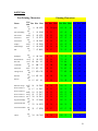
ASCII Table
Non-Printing Characters
Name
null
start of heading
start of text
end of text
end of xmit
enquiry
acknowledge
bell
backspace
horizontal tab
line feed
vertical tab
form feed
carriage feed
shift out
shift in
data line escape
device control 1
Ctrl
Dec Hex Char Dec Hex Char Dec Hex Char Dec Hex Char
char
ctrl-
@
ctrl-
A
ctrl-B
ctrl-C
ctrl-
D
ctrl-E
ctrl-F
ctrl-
G
ctrl-
H
ctrl-I
ctrl-J
ctrl-
K
ctrl-L
ctrl-
M
ctrl-
N
ctrl-
O
ctrl-P
ctrl-
Q
device control 2 ctrl-R
device control 3 ctrl-S
device control 4 ctrl-T
neg acknowledge
synchronous idel
end of xmit block
cancel
Printing Characters
ctrl-
U
ctrl-
V
ctrl-
W
ctrl-
X
0
00 NUL
32
20 Space
64
40
@
96
60
`
1
01 SOH
33
21
!
65
41
A
97
61
a
2
3
02 STX
03 ETX
34
35
22
23
"
#
66
67
42
43
B
C
98
99
62
63
b
c
4
04 EOT
36
24
$
68
44
D
100
64
d
5
6
05 ENQ
06 ACK
37
38
25
26
%
&
69
70
45
46
E
F
101
102
65
66
e
f
7
07 BEL
39
27
'
71
47
G
103
67
g
8
08 BS
40
28
(
72
48
H
104
68
h
9 09 HT
10 0A LF
41
42
29
2A
)
*
73
74
49
4A
I
J
105
106
69
6A
i
j
11
0B VT
43
2B
+
75
4B
K
107
6B
k
12
0C FF
44
2C
,
76
4C
L
108
6C
l
13
0D CR
45
2D
-
77
4D
M
109
6D
m
14
0E SO
46
2E
.
78
4E
N
110
6E
n
15
0F SI
47
2F
/
79
4F
O
111
6F
o
16
10 DLE
48
30
0
80
50
P
112
70
p
17
11 DC1
49
31
1
81
51
Q
113
71
q
18
19
20
12 DC2
13 DC3
14 DC4
50
51
52
32
33
34
2
3
4
82
83
84
52
53
54
R
S
T
114
115
116
72
73
74
r
s
t
21
15 NAK
53
35
5
85
55
U
117
75
u
22
16 SYN
54
36
6
86
56
V
118
76
v
23
17 ETB
55
37
7
87
57
W
119
77
w
24
18 CAN
56
38
8
88
58
X
120
78
x
36
end of medium
ctrl-
Y
substitute
ctrl-Z
escape
ctrl-[
file separator
ctrl-\
group separator
ctrl-]
record separator ctrl-^
unit separator
ctrl-_
25
19 EM
57
39
9
89
59
Y
121
79
y
26 1A SUB
27 1B ESC
28 1C FS
29 1D GS
30 1E RS
31 1F US
58
59
60
61
62
63
3A
3B
3C
3D
3E
3F
:
;
<
=
>
?
90
91
92
93
94
95
5A
5B
5C
5D
5E
5F
Z
[
\
]
^
_
122
123
124
125
126
127
7A
z
7B
{
7C
|
7D
}
7E
~
7F DEL
37
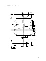
CDN366 Enclosure Dimensions
1.25
0.65
0.45
3.80
4.30
3.30
0.50
0.12
Mtg. Holes
(2) 0.19 DIA.
1.225
1.225
0.725
0.625 DIA. On Case Wall
0.70
0.542
1.10
38
CDN366 Template
Class
Instance
Attribute
Default
Setting
Unit
Comments
39
Allen-Bradley Home Page
Welcome to our site!
Web Tools
Search
Register to become an
A-B Internet Member
FAQ
Contact Us
Modify User Profile
Reset Password
Resources
* Product Directory *
Product Directory
Find a Local Distributor
Shop On-Line
Events Listing
A-B Journal
The VIEW Magazine
ControlNews
Catalogs
Manuals On-Line
Automation Bookstore
AutoCAD Library
Services
Product Support
Product Upgrades
Product Certification
Product Testing
Customer Training
Sales Support Training
NEW, EASY METHOD TO VIEW MCC WIRING DIAGRAMS
We've added over 600 wiring diagrams (in AutoCAD and PDF
format) and included more than 60 varieties of units. Select from
listings in simple text and industry acronyms (no need to know
catalog numbers) to view the wiring diagrams.
POWERFLEX 700 AC DRIVE
PowerFlex 700 bookshelf design saves you volumes of space.
Convenient side-by-side mounting optimizes panel space and gives
you unmatched configuration flexibility.
COMPACTLOGIX
Part of the Logix family, CompactLogix offers compact design,
expansive modularity, and numerous communication capabilities
for machine level control.
MOBILEVIEW PORTABLE HMI
Find out about the power of portability with the new family of
Allen-Bradley MobileView Portable HMI products - for
information where you need it.
GUARDPLC 1200 AND 2000 SAFETY PLCS
Now you can combine personnel safety and productivity gains
with the first in a line of
Allen-Bradley safety control solutions.
PREVIOUS FEATURES...
http://www.ab.com/ (1 of 2) [2/19/2002 1:24:08 PM]
Allen-Bradley Home Page
Copyright © 2002, Rockwell Automation. All rights reserved.
Important Notices
http://www.ab.com/ (2 of 2) [2/19/2002 1:24:08 PM]
Manuals On-line -- I/O Library
I/O Library
System Requirements |
FAQ
Web Tools
Search
Register to become an
A-B Internet Member
FAQ
Contact Us
· 1734, 1734D POINT I/O
· 1746/1747 I/O Modules
· 1756 ControlLogix
· 1769 Compact I/O Modules
· 1771 I/O Modules
· 1790, 1790D Compact Block LDX
· 1791 Block I/O
· 1791D, 1791R Compact Block I/O
· 1792, 1792D ArmorBlock I/O Modules
· 1793 FLEX Integra
· 1794 FLEX I/O Modules
· 1797 FLEX Ex Modules
· 1798 FlexArmor Modules
· 1799 Embedded I/O Modules
· 6008 I/O Scanner Modules
Modify User Profile
Reset Password
Resources
Product Directory
Find a Local Distributor
1746/1747 I/O Modules
I/O Adapter Modules | Analog I/O Modules | Chassis, Power Supplies, RTBs | Digital I/O Modules
Communication Modules | Positioning I/O Modules | Process Control I/O Modules | Programming Device
Shop On-Line
Events Listing
A-B Journal
The VIEW Magazine
I/O Adapter Modules
Product/Title
Catalog Number
Publication Type
ControlNet Adapter Module
1747-ACN15, -ACNR15
Installation Instructions May 2001 1747-IN017C-EN-P
Product Profile
ControlNews
Date
Nov 2000
Publication Number
1747-PP008A-EN-P
Firmware Release Note May 2001 1747-RN653A-EN-P
Catalogs
Manuals On-Line
Automation Bookstore
RSNetWorx for ControlNet
Compatibility with the SLC
ControlNet Scanner/Adapter
1747-ACN15, -ACNR15, -SCNR
Release Note
May 2000 CNET-RN001A-EN-P
SLC 500 Remote I/O Adapter
Module
1747-ASB
Product Data
Apr 1996
AutoCAD Library
Services
1747-2.38
Installation Instructions May 2001 1747-IN014B-EN-P
User Manual
Dec 1996
1747-6.13
Product Support
Product Upgrades
Product Certification
Product Testing
Customer Training
Sales Support Training
Analog I/O Modules
Product
Catalog Number
Publication Type
Date
Publication Number
1746 Eight Channel Analog Input
Module for Demanding Process
Control
1746
Product Profile
Apr 1997
1746-1.11
Analog I/O Modules for SLC based 1746-FIO4I and -FIO4V
Processors
User Manual
May 1995 1746-6.9
Document Update
Jan 1996
Analog I/O Modules for SLC 500™ 1746-FIO4I, -FIO4V, -NI4, -NI8, -NIO4I,
Programmable Controllers
-NIO4V, -NO4I, -NO4V, -NI8, -NI16I,
-NO4I, AND -NO4V
Technical Data
May 2000 1746-TD001A-EN-P
SLC500 32-Point Discrete I/O
Module
1746-IB32, -IV32, -OB32, -OB32E, -OV32
Installation Instructions Aug 2001
1746-IN023A-EN-P
SLC500 Analog I/O Modules
1746-NI4, -NIO4I, -NIO4V, -NO4I, -NO4V, Installation Instruction Mar 2000
-FIO4I, and FIO4V
1746-IN008A-US-P
SLC 500 Analog I/OModule
1746-NI4, -NIO4I, -NIO4V, -NO4I, -NO4V
1746-6.4
SLC Analog Input Module
1746-NI8
http://www.ab.com/manuals/io/1746/index.html (1 of 4) [2/19/2002 1:28:19 PM]
User Manual
Jan 1996
1746-6.9-DU1
Installation Instructions Feb 2000
1746-IN006A-US-P
User Manual
1746.6.8
Apr 1997
Manuals On-line -- I/O Library
High Density Analog Input Modules 1746-NI8, -NI16I, -NI16V
for Demanding Process Control
Applications
SLC 500 Analog Input Modules
SLC 500 RTD/Resistance Input
Module
1746-NI16I, 1746-NI16V
1746-NR4 and 1746-NR8
Product Profile
Nov 1999
1746-PP001A-US-P
User Manual
Dec 1999
1746-UM001A-US-P
Installation Instructions Dec 1999
1746-IN001B-US-P
Technical Data
1746-TD007B-EN-P
Aug 2000
Installation Instructions May 2001 1746-IN012B-EN-P
1746-NR8 Eight Channel
RTD/Resistance Input Module
SLC500 RTD/Resistance Input
Module
1746-NR8
SLC 500 Thermocouple/mV Input
Module
1746-NT4, Series B
SLC 500 Thermocouple/mV Input
Module
1746-NT4, -NT8, -INT4
User Manual
Jun 1998
1746-6.7
Product Profile
Dec 1999
1746-PP003A-US-P
Installation Instructions May 2000 1746-IN007B-EN-P
User Manual
June 2000 1746-UM003A-EN-P
Installation Instructions Jun 2001
1746-IN010B-EN-P
User Manual
Jan 1996
1746-6.6.1
Technical Data
Apr 2000
1746-TD002A-EN-P
1746-NT8 for the SLC 500 Platform 1746-NT8
Product Profile
Nov 1999
1746-PP002A-US-P
SLC500 Thermocouple/mV Analog
Input Module
Installation Instructions Mar 2001
1746-IN015B-EN-P
User Manual
1746-6.22
Jul 1999
SLC500 Thermocouple/mV Input
Module Terminal Block
1746-RT34
Installation Instructions Mar 2001
1746-IN018B-EN-P
SLC500 RTD/Resistance Input
Module Terminal Block
1746-RT35
Installation Instructions Mar 2001
1746-IN019B-EN-P
SLC500 Input Simulator
1746-SIM
Installation Instructions Oct 2001
1746-IN024A-EN-P
Program Storage Device Installation 1747-PSD
Instructions
Installation Instructions Nov 2001
1747-IN001B-EN-P
Publication Type
Date
Publication Number
SLC Expansion Chassis -1746-A2
Inaccurate I/O Configuration Report
for SLC 500 with RSLogix 500
Programming Software
Application Note
Feb 2000
1746-AP001A-US-P
SLC Modular Chassis
1746-A4, -A7, -A10, and -A13 Series B
Installation Instructions Sep 2000
1746-IN016A-MU-P
SLC 500 Modular Chassis and
Power Supplies
1746-A4, -A7, -A10, and -A13; Power Supply Technical Data
Cat. Nos. 1746-P1, -P2, -P3, -P4, -P5, -P6 and
-P7
SLC 500 Power Supplies
Chassis, Power Supplies, RTBs
Product/Title
Catalog Number
Apr 2000
1746-TD003A-EN-P
1746-P1, 1746-P2, 1746-P3, 1746-P4,
1746-P5, 1746-P6, 1746-P7)
Installation Instructions Oct 2001
1746-IN004B-MU-P
12/24V dc Power Supply Expands
SLC 500 Control Capabilities
1746-P7
Product Profiles
1746-1.21
Removable Terminal Blocks
1746-RT25B, -RT25C, -RT25G, -RT25R, and Installation Instructions Jun 1999
-RT32
1746-5.9
Product/Title
Catalog Number
Publication Type
Publication Number
Discrete I/O Modules
1746 Series
Installation Instructions Jan 2000
1746-IN005A-US-P
Technical Data
1746-2.35
Mar 1999
Digital I/O Modules
Discrete Input and Output Modules 1746-IA4, -IA8, -IA16, -IB8, -IB16, -IB32,
-IC16, -IG16, -IH16, -IM4, -IM8, -IM16,
-IN16, -ITB16, -ITV16, -IV8, -IV16, -IV32,
-OA8, -OA16, -OAP12, -OB8, -OBP8,
-OB16, -OBP16, -OB32, -OG16, -OV8,
-OV16, -OVP16, -OV32, -OW4, -OW8,
-OW16, -OX8, -IO4, -IO8, -IO12, -I012DC
http://www.ab.com/manuals/io/1746/index.html (2 of 4) [2/19/2002 1:28:19 PM]
Date
Jul 1999
Manuals On-line -- I/O Library
SLC500 32-Point I/O Modules
1746-IB32, -IV32, -OB32, and -OV32
Installation Instructions Dec 1998
1746-5.19
Communication Modules
Product/Title
Catalog Number
Publication Type
Date
Publication Number
1746-BAS Module Floating Point
Conversion
1746-BAS
Release Notes
Sep 1999
1746-DU001A-US-P
SLC500 BASIC and BASIC-T
Modules
1746-BAS and 1746-BAS-T
BASIC Language
Installation Instructions Mar 2000
1746-IN009A-US-P
User Manual
Apr 2000
1746-UM004A-US-P
Reference Manual
Apr 2000
1746-RM001A-US-P
SLC500 BASIC Module and
BASIC Development Software
1746-BAS and 1747-PBASE
Technical Data
Aug 2000
1746-TD005B-EN-P
1746-BAS-T High Performance
Basic Module
SLC500 BASIC and Basic-T
Modules
1746-BAS-T
Product Profile
Dec 1999
1746-PP004A-US-P
User Manual
Apr 2000
1746-US004A-US-P
BASIC Development Software
1746-PBASE
Programming Manual
May 2000 1746-PM001A-US-P
Application Note
Sep 1996
1746-2.41
Product Profile
Nov 1999
1747-PP001A-US-P
Technical Data
Feb 2000
1747-TD002A-US-P
ASCII Data Transfer to the SLC
500 BASIC Module (Series B)
Back Up Your SLC 500 Control
System with the 1747-BSN
1747-BSN
Backup Scanner Module
Direct Communication Module
Distributed I/O Scanner
1747-DCM
1747-DSN
Installation Instructions Sep 1999
1747-5.38
User Manual
Oct 1999
1747-6.22
Product Data
Jan 1997
1747-2.33
Installation Instructions Feb 2000
1747-IN005A-US-P
User Manual
Jun 1996
1747-6.8
Product Data
May 1998 1747-2.35
DH-485/RS-232C Interface Module 1747-KE
Installation Instructions Feb 2000
DH-485/RS-232C Interface Module 1747-KEU
Firmware Upgrade
Installation Instructions March 1994 1747-5.4
ControlNet Messaging Module
1747-KFC15
Product Profile
Dec 1999
1747-PP004A-US-P
API Software for 1746 I/O PCI
Interface and 17147-OC Open
Controller
1747-OCF, -PCIS
User Manual
Jun 2000
1747-UM002A-US-P
Chassis Interface Module for 1746
Local I/O
1747-PCIL
PCI Bus Card for 1746 Local I/O
1747-PCIS/CIS2/PCIS2
ControlNet Scanner Module
1747-SCNR
1747-SDN DeviceNet Scanner
Module
1747-SDN/B
1747-SDN and Explicity Messaging 1747-SDN
Remote I/O Scanner
1747-SN
1747-IN006A-US-P
Installation Instructions Apr 1998
1747-5.32
Release Notes
1747-5.32-RN1
Jul 1998
Installation Instructions Apr 1998
1747-5.31
Product Profile
Mar 2001
1747-PP005A-US-P
Reference Manual
Feb 2001
1747-RM623B-EN-P
Installation Instructions Aug 2001
1747-IN058B-EN-P
Release Note
Jul 2001
1747-RN007B-EN-P
Release Note
Jun 1999
1747-6.5.2-RN2
Product Data
Mar 1996
1747-2.34
User Manual
Jul 1996
1747-6.6
Installation Instructions Jun 01
1747-IN060B-EN-P
Publication Type
Publication Number
Positioning I/O Modules
Product/Title
Catalog Number
http://www.ab.com/manuals/io/1746/index.html (3 of 4) [2/19/2002 1:28:19 PM]
Date
Manuals On-line -- I/O Library
1746 Multi-Channel High-Speed
1746
Counter Module for Demanding
Positioning, Packaging and Material
Handling Applications
Blow Molding Module
High-Speed Counter Module
1746-BLM
1746-HSCE
Multi-Channel High-Speed Counter 1746-HSCE2
Module
Product Profiles
Aug 1999
1746-1.20
Product Profile
Feb 2001
1746-PP019B-EN-P
Installation Instructions Jan 2001
1746-IN014B-EN-P
Product Data
1746-2.32
Jan 1997
Installation Instructions Apr 2001
1746-IN011B-EN-P
User Manual
Apr 1996
1746-6.5
User Manual
Apr 2000
1746-UM002A-US-P
Product Data
Jul 1999
1746-2.44
Installation Instructions Feb 2000
1746-IN002A-US-P
1746-999-121
Stepper Controller Module
1746-HSTP1
User Manual
Dec 1999
Mold Pressure Module
1746-MPM
Installation Instructions Jul 1998
1746-5.13
Publication Type
Date
Publication Number
Barrel Temperature Control Module 1746-BTM
User Manual
Apr 2001
1746-UM010B-EN-P
Open-Loop Velocity Control
Module Addresses Common
Hydraulic Problems
1746-QV
Product Profile
Feb 1997
1746-1.10
Catalog Number
Publication Type
Date
Publication Number
SLC-500 and MicroLogix Program 1747
Storage Device for Easy Backup,
Storage and Transfer of PLC
Programs
Product Profile
May 1993 1747-1.22
Data Table Access Module
(Engineer's Reference)
Data Table Access Module
(Operator's Reference)
1747-DTAM
Pocket Quick Reference May 1993 1747-902
Program Storage Device
1747-PSD
Process Control I/O Modules
Product/Title
Catalog Number
Programming Device
Product/Title
May 1993 1747-903
Document Update
Sep 2001
Installation Instructions Nov 2001
Copyright © 2002, Rockwell Automation. All rights reserved.
Important Notices
http://www.ab.com/manuals/io/1746/index.html (4 of 4) [2/19/2002 1:28:19 PM]
1747-DU003B-EN-P
1747-IN001B-EN-P
Packing Data
PK
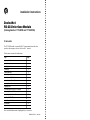
Installation Instructions
DeviceNet
RS232 Interface Module
(Catalog Number 1770-KFD and 1770-KFDG)
To the Installer
The 1770-KFD module is a portable RS-232 communication interface that
provides a host computer access to a DeviceNett network.
This document contains this information:
topic
page
purpose and audience
2
precautionary statements
2
handling the module
4
terminology
4
related publications
4
contents of your order
5
introduction to the RS232 module
8
communicating on DeviceNet
9
mounting the module
10
supplying power
12
connecting cables via RS232 to a computer
14
connecting cables via RS232 to a modem
16
connecting cables via DeviceNet
17
installing the 1770KFD driver
22
interpreting status indicators
23
specifications
25
support services
26
New or modified information is highlighted by a revision bar.
Publication 17705.6 - June 1996
2
DeviceNet RS-232 Interface Module
Purpose
Use this document to learn how to install and use the DeviceNet RS-232
interface module.
Audience
Read this manual before you install or use the DeviceNet RS-232 interface
module. You should be familiar with DeviceNet technology.
Precautionary Statements
Important User Information
Because of the variety of uses for the products described in this publication, those responsible
for the application and use of this control equipment must satisfy themselves that all necessary
steps have been taken to assure that each application and use meets all performance and
safety requirements, including any applicable laws, regulations, codes and standards.
The illustrations, charts, sample programs and layout examples shown in this guide are intended
solely for purposes of example. Since there are many variables and requirements associated with
any particular installation, AllenBradley does not assume responsibility or liability (to include
intellectual property liability) for actual use based upon the examples shown in this publication.
AllenBradley publication SGI1.1, Safety Guidelines for the Application, Installation, and Maintenance
of Solid State Control (available from your local AllenBradley office), describes some important
differences between solidstate equipment and electromechanical devices that should be taken into
consideration when applying products such as those described in this publication.
Reproduction of the contents of this copyrighted publication, in whole or in part, without written
permission of AllenBradley Company, Inc., is prohibited.
Throughout this document we use notes to make you aware of safety considerations:
!
ATTENTION: This notation identifies information about practices or circumstances
that can lead to personal injury or death, property damage or economic loss.
Attention statements help you to:
S identify a hazard
S avoid the hazard
S recognize the consequences
Important: This notation identifies information that is critical for successful application and
understanding of the product.
Publication 17705.6 - June 1996
DeviceNet RS-232 Interface Module
3
European Union Directive Compliance
This product has the CE mark and is approved for installation within the
European Union and EEA regions. It has been designed and tested to meet the
following directives.
EMC Directive: This apparatus is tested to meet Council Directive 89/336/EEC
Electromagnetic Compatibility (EMC) using a technical construction file and the
following standards, in whole or in part:
• EN 50081-2
• EN 50082-2
EMC – Generic Emission Standard,
Part 2 – Industrial Environment
EMC – Generic Immunity Standard,
Part 2 – Industrial Environment
The product described in this manual is intended for use in an industrial
environment.
Low Voltage Directive: This apparatus is also designed to meet Council
Directive 73/23/EEC Low Voltage, by applying the safety requirements of
EN 61131-2 Programmable Controllers, Part 2 – Equipment Requirements
and Tests.
For specific information that the above norm requires, see the appropriate
sections in this manual, as well as the following Allen-Bradley publications:
• Industrial Automation Wiring and Grounding Guidelines,
publication 1770-4.1
• Guidelines for Handling Lithium Batteries, publication AG-5.4
• Automation Systems Catalog, publication B111
Publication 17705.6 - June 1996
4
DeviceNet RS-232 Interface Module
Handling the Module
ATTENTION: This RS-232 module uses CMOS technology, which is highly
sensitive to electrostatic discharge (ESD). ESD may be present whenever you
are handling the module.
Take these precautions to guard against electrostatic damage:
• Avoid touching the interface connector pins on the RS-232 module.
• If the module is not in use, store it in the anti-static bag in which it was
shipped.
It is not necessary to wear an ESD wrist strap while handling the 1770-KFD
module.
Terminology
this term
means
DeviceNet
an open communication network designed to connect control
systems to plant floor devices, e.g., sensors, push buttons,
motor starters, and drives
DeviceNet is based on commercially available technology and
can be used by any company to develop interoperable
products.
node configuration
to configure the node address and data rate before a device is
connected to a DeviceNet network
parameter configuration
to configure the operational parameters of a DeviceNet device
pointtopoint configuration
a twonode DeviceNet network consisting of a 1770KFD
interface module and a device
Related Publications
title
DeviceNet Manager Software User Manual
DeviceNet Cable System Planning & Installation Manual
DeviceNet RS232 Interface Module Communication Protocol
Reference Manual
Publication 17705.6 - June 1996
publication number
17876.5.3
DN6.7.1
17706.5.22
DeviceNet RS-232 Interface Module
5
Contents of Your 1770KFD Order
With this package you should receive:
1770KFD
driver disk
1770KFD
module
DIN rail
mounting brackets
unsealed DeviceNet
terminal connector
6 ft, 9pin Dshell RS232
nullmodem cable
KFD instructions
DIN rail
mounting bracket screws
•
•
•
•
•
•
•
one DeviceNet RS-232 interface module, catalog no. 1770-KFD
one 1770-KFD driver diskette
two DIN rail mounting brackets
four DIN rail mounting bracket screws
one 6 ft, 9-pin D-shell RS-232 null-modem cable
one unsealed DeviceNet terminal connector
one copy of publication 1770-5.6, DeviceNet RS-232 Interface Module
Installation Instructions
If you ordered catalog no. 1770-KFDG, your order also includes a global 9V ac
power supply adapter (90 – 260V ac).
If you are missing any of these pieces, contact your Allen-Bradley
sales representative.
Publication 17705.6 - June 1996
6
DeviceNet RS-232 Interface Module
Available options:
• global 9V ac power supply adapter (90 – 260V ac), which comes with
catalog no. 1770KFDG/A
• domestic 9V ac power supply adapter (120V ac), which you can order
separately as catalog no. 1787USADPTR/A
Each adapter connects to the power supply connector on the 1770-KFD module.
See page 12 for additional information.
Publication 17705.6 - June 1996
DeviceNet RS-232 Interface Module
7
• an 8 ft, 5-pin DeviceNet unsealed probe cable (catalog no. 1787-PCABL),
which you can order separately
Probe cable
• a 6 ft, sealed T-tap DeviceNet connector cable (catalog no. 1787-TCABL),
which you can order separately
Ttap cable
This cable connection lets the 1770-KFD module and a device connected to
the module in a point-to-point configuration draw power from the network.
• a 6 ft, unsealed-to-sealed DeviceNet drop cable (catalog no. 1787-MCABL),
which you can order separately
Unsealed drop cable
Each cable connects to the 5-pin unsealed receptacle on the 1770-KFD module.
See cable connection information beginning on page 17.
Publication 17705.6 - June 1996
8
DeviceNet RS-232 Interface Module
Introducing the 1770KFD Interface Module
The 1770-KFD module, described in Figure 1, is a portable RS-232
communication interface that provides a host computer access to a
DeviceNet network.
RS232 cable
1770KFD
module
RS232 serial port
host
computer
Figure 1
1770KFD module
Side 1
power
switch
power supply
connector
9pin Dshell
RS232 connector
Module Status
indicator
Side 2
RS232 Status
indicator
Network Status
indicator
5pin unsealed
connector
Publication 17705.6 - June 1996
wiring
connection
diagram
20294
DeviceNet RS-232 Interface Module
9
Communicating on DeviceNet
The 1770-KFD module lets you communicate:
• point-to-point (host computer directly to device via the 1770-KFD module)
The host computer uses a point-to-point connection for node and/or
parameter configuration.
device
1770KFD
module
DeviceNet cable
RS232 cable
host
computer
power supply
• via a DeviceNet network connection
1771SDN scanner
1747SDN scanner
DeviceNet network
devices
RS232 cable
1770KFD
module
host
computer
Publication 17705.6 - June 1996
10
DeviceNet RS-232 Interface Module
The 1770-KFD module performs data transmission, management, and local
network diagnostics.
Allen-Bradley DeviceNet Manager software, 1787-MGR, manages data
transmission and reception through the 1770-KFD interface module from a
personal computer (Windowst operating system).
Mounting the 1770KFD Module
You can mount the module on a DIN rail.
1. Use the four screws to attach the two mounting brackets to the back of the
module.
20296
Publication 17705.6 - June 1996
DeviceNet RS-232 Interface Module
11
2. Snap the mounting brackets onto the DIN rail.
20297
Publication 17705.6 - June 1996
12
DeviceNet RS-232 Interface Module
Supplying Power to the 1770KFD Module
The 1770-KFD module can be powered from either an external power supply or
from a DeviceNet network.
Supplying Power via AC Wall Adapter
Figure 2 shows the power supply, catalog no. 1787-USADPTR, that takes 120V
ac and outputs 9V dc at 1 amp.
Figure 2
Domestic 9V ac wall adapter
20299
Figure 3 shows the global power supply, which takes 90 – 260V ac,
47 – 63 Hz, and outputs 9V dc. This power supply is available only with the
1770-KFD module as catalog no. 1770-KFDG.
Publication 17705.6 - June 1996
DeviceNet RS-232 Interface Module
13
Figure 3
Global 9V ac wall adapter
20300
Important: You must supply the cable between the adapter and the outlet.
Supplying Power via Network
The DeviceNet network can power the 1770-KFD module.
Important: When the module is connected to a powered DeviceNet network,
the network connection overrides the external power supply.
Supplying Power to a Device
The module can supply power to a device in a point-to-point connection.
The device being powered in a point-to-point connection can draw a maximum
of 100 mA at 12V dc ±5%.
Publication 17705.6 - June 1996
14
DeviceNet RS-232 Interface Module
Connecting Cables via RS232 to a Computer
Use the wiring key molded on the bottom of the 1770-KFD module when
connecting the RS-232 cable to a computer.
PIN 1
PIN 2
PIN 3
PIN 4
PIN 5
PIN 6
PIN 7
PIN 8
PIN 9
DCD
RXD
TXD
DTR
GND
DSR
RTS
CTS
RI
R
S
2
3
2
Bottom of
the 1770KFD
20295a
Use these wiring configurations:
DeviceNet
RS232
Interface
GND
RXD
TXD
DTR
5
2
3
4
DSR
DCD
RTS
CTS
RI
6
1
7
8
9
female DB9
connector
Host
RS232
Port
DeviceNet
RS232
Interface
7
2
3
6
8
20
GND
RXD
TXD
DTR
5
2
3
4
DSR
DCD
RTS
CTS
RI
6
1
7
8
9
GND
TXD
RXD
DSR
DCD
DTR
4 RTS
5 CTS
22 RI
female DB25
connector
Publication 17705.6 - June 1996
female DB9
connector
Host
RS232
Port
5
3
2
6
1
4
GND
TXD
RXD
DSR
DCD
DTR
7 RTS
8 CTS
9 RI
female DB9
connector
DeviceNet RS-232 Interface Module
15
RS-232 Cable Connections (via 9-pin serial port connector)
These pin numbers correspond with these connections:
pin number
abbreviation
description
direction
1
DCD
data carrier detect
in
2
RXD
receive data
in
3
TXD
transmit data
out
4
DTR
data terminal ready
out
5
GND
signal ground
-
6
DSR
data set ready
in
7
RTS
request to send
out
8
CTS
clear to send
in
9
RI
ring indicator
in
Connect the 1770-KFD module to a computer by using the RS-232 cable.
IMPORTANT: If you build your own RS232 cable,
it must not be longer than 10M/32.8'.
RS232 cable to host computer
retentive locking screws
20295b
Publication 17705.6 - June 1996
16
DeviceNet RS-232 Interface Module
Using the Interface Module with a Portable Computer
Some portable computers have power-saving modes that power down the serial
ports during inactive periods, occurring most often when batteries power the PC.
The serial-port power-saving feature causes the RS-232 interface module to go
offline and to cease communication with DeviceNet Manager. You should
disable the serial-port power-saving feature to use the RS-232 interface module
with DeviceNet Manager.
If you experience a problem with the RS-232 interface module going offline
unexpectedly, use the setup program of your portable computer to disable the
serial-port power-saving feature.
Connecting Cables via RS232 to a Modem
You can connect a 1770-KFD module to these standard dial-up modems:
• DTE-controlled answer
• auto-answer
DeviceNet
RS232
Interface
DCD
RXD
TXD
DTR
GND
DSR
RTS
CTS
RI
1
2
3
4
5
6
7
8
9
female DB9
connector
Modem
RS232
Port
DeviceNet
RS232
Interface
Modem
RS232
Port
8
3
2
20
7
6
4
5
22
DCD
RXD
TXD
DTR
GND
DSR
RTS
CTS
RI
1
2
3
4
5
6
7
8
9
DCD
RXD
TXD
DTR
GND
DSR
RTS
CTS
RI
male DB25
connector
Publication 17705.6 - June 1996
1
2
3
4
5
6
7
8
9
female DB9
connector
DCD
RXD
TXD
DTR
GND
DSR
RTS
CTS
RI
male DB9
connector
DeviceNet RS-232 Interface Module
17
Connecting Cables via DeviceNet
Follow these steps to connect the 1770-KFD module to a DeviceNet network:
1. Connect the DeviceNet cable (trunkline or dropline) to the unsealed
DeviceNet terminal connector.
DeviceNet cable
(trunkline or dropline)
red
white
shield
unsealed DeviceNet
terminal connector
blue
black
20295c
2. Connect the terminal connector to the 1770-KFD module.
Important: DeviceNet cable connections should match color bars/electrical
diagram on top of 1770-KFD module. See the table below.
pin number
wire color
abbreviation
1
black
V-
2
blue
data low
3
clear
shield
4
white
data high
5
red
V+
description
power return
data line
between cable jacket and wire
data line
positive voltage (hot)
Publication 17705.6 - June 1996
18
DeviceNet RS-232 Interface Module
Connecting the 1770-KFD Module to DeviceNet Devices
(Point-to-Point)
You can connect the module to a sealed or an unsealed device in a point-to-point
configuration.
Connect to an unsealed device in one of two ways:
• use a 1787-PCABL probe cable
1770KFD
Probe Cable
Power
Supply
Generic
Unsealed
Device
20409a
• use DeviceNet drop or trunk cable
1770KFD
DeviceNet Drop or
Trunk Cable
Generic
Unsealed
Device
Power
Supply
20409b
Publication 17705.6 - June 1996
DeviceNet RS-232 Interface Module
19
Connect to a sealed device in one of three ways:
• use a 1787-TCABL T-tap cable (and power supply)
1770KFD
Ttap Cable
Power
Supply
Generic
Sealed
Device
20409c
• use a 1787-TCABL T-tap cable (and draw power from the network)
Network
1770KFD
Ttap Cable
Generic
Sealed
Device
20409d
Publication 17705.6 - June 1996
20
DeviceNet RS-232 Interface Module
• use a 1787-MCABL unsealed drop cable (and power supply)
1770KFD
Ttap
Unsealed Drop Cable
Power
Supply
Generic
Sealed
Device
20410a
Probing a Network
You can probe a sealed or an unsealed network with the 1770-KFD module.
Probe an unsealed network in one of two ways:
• use a 1787-PCABL probe cable
1770KFD
Probe Cable
Generic
Unsealed
Device
20766-M
Publication 17705.6 - June 1996
DeviceNet RS-232 Interface Module
21
• use a DeviceNet terminal connector
1770KFD
20767-M
Probe a sealed network in this way:
• use a 1787-MCABL unsealed drop cable
Network
1770KFD
Unsealed Drop Cable
20410e
Publication 17705.6 - June 1996
22
DeviceNet RS-232 Interface Module
Installing the 1770KFD Driver
If you are using a WinDNett-compatible application, you must install the
1770-KFD driver.
Follow these steps:
1. Start Windows 3.1, Windows 95, or Windows NT.
2. Select Run from the File menu.
3. On the command line, type
a:\setup
as shown here:
4. Press OK.
5. Follow the instructions in each dialog box until you see the message:
Installation Complete
Publication 17705.6 - June 1996
DeviceNet RS-232 Interface Module
23
Interpreting Status Indicators
The three status indicators on the module give you information about your
network and its connections. Figure 4 identifies each status indicator.
Figure 4
Status indicator locations
Network
Status Indicator
NETWORK
STATUS
Module
Status Indicator
MODULE
STATUS
DC IN
(9V)
DeviceNET
RS232
RS232
STATUS
RS232
Status Indicator
1770KFD
20298
The tables on page 24 outline the indicator condition and the corresponding
status, and explain what each condition means to you.
Publication 17705.6 - June 1996
24
DeviceNet RS-232 Interface Module
Module Status Indicator
condition
status
indicates
off
no power
no power applied to device
solid green
device OK
device is operating in normal condition; KFD
module is on line, i.e., has baud rate detected
flashing green
not configured
device is operating in normal condition; waiting
for initialization from host (in `autobaud' mode)
solid red
critical fault
device has unrecoverable fault; replace it
flashing red
noncritical fault
device has recoverable fault; to recover:
• reconfigure device
• reset device
• perform error recovery
Network Status Indicator
condition
status
indicates
off
off line
KFD DeviceNet is off line
flashing green
on line
KFD DeviceNet is on line, but not
communicating
solid red
link failed
(critical)
device has detected an error that has rendered
it incapable of communicating on the link; for
example, detected a duplicate node address or
network configuration error
solid green
on line,
communicating
data being transmitted or received
RS-232 Status Indicator
condition
status
indicates
off
no activity, link OK
no communication activity
flickering green
activity, link OK
data being transmitted or received
solid red
link failed
(critical)
device has detected an error that has rendered
it incapable of communicating of the link
flashing red
link failed
(noncritical)
device has detected recoverable fault; for
example, detected an incorrect baud rate or
parity error
Publication 17705.6 - June 1996
DeviceNet RS-232 Interface Module
25
Specifications
communication rate
RS232 selectable rates:
• 1200 baud
19,200 baud
• 2400
38,400
• 4800
57,600
• 9600
DeviceNet selectable rates:
• 125K baud
• 250K
• 500K
function
to monitor and configure devices on
DeviceNet network
location
anywhere via personal computer
communication port
one 9pin RS232 Dshell
cabling
RS232 cable; see cable diagrams
power requirements:
• ac wall
9V @ 1 amp
• DeviceNet connector
11 - 25V @ (700mA - 300mA)
ambient temperature rating:
• operational
0 to 50°C (32° to 122°F)
• storage
-40°C to 85°C (-40° to 185°F)
ambient humidity rating
5% - 95%
physical:
• size
5.125 x 3.25 x 1.125 in.
(13.017 x 8.255 x 2.857 cm)
• weight
5.5 oz (156 gm)
Agency Certification
(when product or packaging is
marked)
• CSA certified
• CSA Class I, Division 2
Groups A, B, C, D certified
• UL listed
• CE marked for all applicable directives
Publication 17705.6 - June 1996
26
DeviceNet RS-232 Interface Module
Support Services
At Allen-Bradley, customer service means experienced representatives
at Customer Support Centers in key cities throughout the world for sales,
service, and support. Our value-added services include:
Technical Support
•
•
•
•
SupportPlus programs
telephone support and 24-hour emergency hotline
software and documentation updates
technical subscription services
Engineering and Field Services
•
•
•
•
application engineering assistance
integration and start-up assistance
field service
maintenance support
Technical Training
•
•
•
•
lecture and lab courses
self-paced computer and video-based training
job aids and workstations
training needs analysis
Repair and Exchange Services
•
•
•
•
your only “authorized” source
current revisions and enhancements
worldwide exchange inventory
local support
Publication 17705.6 - June 1996
DeviceNet RS-232 Interface Module
27
Publication 17705.6 - June 1996
DeviceNet is a trademark of the Open Device Vendors Association (ODVA).
WinDNet and PLC-5 are trademarks of Allen-Bradley Company, Inc.
Windows and Windows NT are trademarks of Microsoft.
Worldwide representation.
Argentina • Australia • Austria • Bahrain • Belgium • Brazil • Bulgaria • Canada • Chile • China, PRC •
Colombia • Costa Rica • Croatia • Cyprus • Czech Republic • Denmark • Ecuador • Egypt • El Salvador •
Finland • France • Germany • Greece • Guatemala • Honduras • Hong Kong • Hungary • Iceland • India •
Indonesia • Ireland • Israel • Italy • Jamaica • Japan • Jordan • Korea • Kuwait • Lebanon • Malaysia •
Mexico • Netherlands • New Zealand • Norway • Pakistan • Peru • Philippines • Poland • Portugal •
Puerto Rico • Qatar • Romania • Russia-CIS • Saudi Arabia • Singapore • Slovakia • Slovenia • South
Africa, Republic • Spain • Sweden • Switzerland • Taiwan • Thailand • Turkey • United Arab Emirates •
United Kingdom • United States • Uruguay • Venezuela • Yugoslavia
AllenBradley Headquarters, 1201 South Second Street, Milwaukee, WI 53204 USA
Tel: (1) 414 3822000 Fax: (1) 414 3824444
Publication 17705.6 - June 1996
Supersedes Publication 17705.6 - October 1995
October 1995
PN 95512579
Copyright 1996 AllenBradley Company, Inc. Printed in USA
17846.5.19RN1