1
Installation Instructions
1747-SDN
DeviceNet Scanner Module
Cat. No. 1747-SDN/B
Contents
Use this document as a guide to install the 1747-SDN/B scanner module.
For this information
See page
Important User Information
1
Prevent Electrostatic Discharge
3
Where to Find More Information
4
Module Features
5
External Module Features
7
Hardware and Software Requirements
8
Install the Scanner Module Into the Chassis
9
Connect the Scanner Module to the DeviceNet™ Network
10
Apply Chassis Power
12
Understand the Data Organization of the Scanner Module
12
Program the Scanner Module Using the M0 and M1 Files
16
Upload Input Data from the Scanner Module
20
Download Output Data from the Scanner Module
24
Explicit Message Program Control
27
Troubleshoot the Module and Network
35
For this reference information
Specifications
See page
39
Publication 1747-IN058C-EN-P - May 2002
2
1747-SDN DeviceNet Scanner Module
Important User Information
Because of the variety of uses for the products described in this publication, those
responsible for the application and use of these products must satisfy themselves that all
necessary steps have been taken to assure that each application and use meets all
performance and safety requirements, including any applicable laws, regulations, codes
and standards.
In no event will Allen-Bradley be responsible or liable for indirect or consequential
damage resulting from the use or application of these products.
Any illustrations, charts, sample programs, and layout examples shown in this
publication are intended solely for purposes of example. Since there are many variables
and requirements associated with any particular installation, Allen-Bradley does not
assume responsibility or liability (to include intellectual property liability) for actual use
based upon the examples shown in this publication.
Allen-Bradley publication SGI-1.1, Safety Guidelines for the Application, Installation and
Maintenance of Solid-State Control (available from your local Allen-Bradley office),
describes some important differences between solid-state equipment and
electromechanical devices that should be taken into consideration when applying
products such as those described in this publication.
Reproduction of the contents of this copyrighted publication, in whole or part, without
written permission of Rockwell Automation, is prohibited.
Throughout this publication, notes may be used to make you aware of safety
considerations. The following annotations and their accompanying statements help you
to identify a potential hazard, avoid a potential hazard, and recognize the consequences
of a potential hazard:
WARNING
!
ATTENTION
Identifies information about practices or circumstances that can
cause an explosion in a hazardous environment, which may
lead to personal injury or death, property damage, or
economic loss.
Identifies information about practices or circumstances that can
lead to personal injury or death, property damage, or
economic loss.
!
IMPORTANT
Identifies information that is critical for successful application
and understanding of the product.
Publication 1747-IN058C-EN-P - May 2002
1747-SDN DeviceNet Scanner Module
ATTENTION
!
3
Environment and Enclosure
This equipment is intended for use in a Pollution Degree 2
industrial environment, in overvoltage Category II applications (as
defined in IEC publication 60664-1), at altitudes up to 2000 meters
without derating.
This equipment is considered Group 1, Class A industrial
equipment according to IEC/CISPR Publication 11. Without
appropriate precautions, there may be potential difficulties
ensuring electromagnetic compatibility in other environments due
to conducted as well as radiated disturbance.
This equipment is supplied as "open type" equipment. It must be
mounted within an enclosure that is suitably designed for those
specific environmental conditions that will be present and
appropriately designed to prevent personal injury resulting from
accessibility to live parts. The interior of the enclosure must be
accessible only by the use of a tool. Subsequent sections of this
publication may contain additional information regarding specific
enclosure type ratings that are required to comply with certain
product safety certifications.
See NEMA Standards publication 250 and IEC publication 60529,
as applicable, for explanations of the degrees of protection
provided by different types of enclosure. Also, see the appropriate
sections in this publication, as well as the Allen-Bradley
publication 1770-4.1 ("Industrial Automation Wiring and
Grounding Guidelines"), for additional installation requirements
pertaining to this equipment.
Prevent Electrostatic Discharge
ATTENTION
!
This equipment is sensitive to electrostatic discharge which can
cause internal damage and affect normal operation. Follow these
guidelines when you handle this equipment:
•
•
•
•
•
•
touch a grounded object to discharge potential static
wear an approved grounding wrist strap
do not touch connectors or pins on component boards
do not touch circuit components inside the equipment
if available, use a static-safe workstation
when not in use, store the equipment in appropriate
static-safe packaging
Publication 1747-IN058C-EN-P - May 2002
4
1747-SDN DeviceNet Scanner Module
Where to Find More Information
The following table describes related documentation. To order a copy or to view or
download an online version, visit The Automation Bookstore at:
www.theautomationbookstore.com
For information about:
See this document:
Publication number:
Configuring the scanner module and
associated hardware in an example
application
SLC 500™ DeviceNet Scanner Module
User Manual
1747-6.5.5
Performing the ControlFlash Update
ControlFlash Firmware Upgrade Kit User
Manual
1756-6.5.6
RSLogix 500™ software
Getting Results with RSLogix 500
9399-RL50GR
RSLinx™ software
Getting Results with RSLinx
9399-WAB32GR
Connecting the DeviceNet network
DeviceNet Cable Planning and Installation
DN-6.7.2
Manual
Publication 1747-IN058C-EN-P - May 2002
1747-SDN DeviceNet Scanner Module
5
Module Features
Slave Mode
Slave mode allows processor-to-processor communication and enables the scanner
to perform as a slave device to another master on the network.
When the scanner module is in slave mode, it exchanges data with only one master.
You control what information is exchanged through scan list configuration and
associated mapping functions of RSNetWorx for DeviceNet software.
This feature has the following variations:
When the scanner module is in:
the scanner:
Null mode
Contains an empty or disabled scan list (default)
Master mode
Serves as a master to one or more slaves but is not
simultaneously serving as a slave to another
master
Slave mode
Serves as a slave to another master
Dual mode
Serves as both a master to one or more slaves and
as a slave to another master simultaneously
Poll
A poll message is a point-to-point transfer of data (0-255 bytes) sent by the scanner
module that solicits a response from a single device. The device responds with its
input data (0-255 bytes).
Strobe
A strobe message is a multicast transfer of data (64 bits in length) sent by the
scanner module that solicits a response from each strobed slave device. There is
one bit for each of the possible 64 node addresses. The devices respond with their
data, which can be as much as 8 bytes.
Change of State
Change of state enables the scanner module to perform a scan:
• whenever a network data change occurs, or
• at a user-configurable heartbeat rate
Because data is only sent on an as-needed basis, this feature increases system
performance by reducing network traffic.
Publication 1747-IN058C-EN-P - May 2002
6
1747-SDN DeviceNet Scanner Module
Cyclic I/O
Cyclic I/O allows you to instruct the scanner module to perform a scan at a specific
send rate.
Because data is only sent at a periodic rate, this feature increases system
performance by reducing network traffic.
Pass-Through
The SLC 500™ “pass-through” feature allows communication with the DeviceNet
network from another network. This feature can be used to adjust and fine tune the
nodes on your network.
The pass-through feature is not intended to replace a 1770-KFD, PCD, PCID, or
PCIDS connection to the network.
System Requirements for Pass-Through
To use the pass-through feature you must meet the following hardware, software
and firmware requirements:
Component
Requirement
Requirement
SLC 500 processor
SLC 5/03 or higher
SLC 5/03 or higher
1747-SDN firmware
4.015 - 5.001
6.001 or higher
RSLinx software
2.10 or higher
2.31 or higher
M0 and M1 files
Configured for 361 words Configured for 395 words
Publication 1747-IN058C-EN-P - May 2002
1747-SDN DeviceNet Scanner Module
7
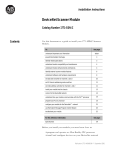
External Module Features
Use this illustration to identify the external features of the scanner module.
DeviceNet
Module Status Indicator
indicates module status
Node address and status
displays numeric codes
and indicates scanner
node address or error
STATUS
NET
MODULE
Network Status Indicator
indicates status of DeviceNet
channel communication link
ADDRESS/ERROR
Access door
Wiring color codes
10-pin linear plug
inserted into DeviceNet
port
Front of module
Publication 1747-IN058C-EN-P - May 2002
8
1747-SDN DeviceNet Scanner Module
Hardware and Software Requirements
Before you install your module you need the following items:
•
•
•
•
personal computer with Microsoft Windows™ 95 or later operating system
RSNetWorx for DeviceNet software, version 2.22 or later
RSLogix 500 software
SLC 1746 chassis with SLC 5/02, 5/03, 5/04 or 5/05 processor
For network communication, you have two options:
• use the pass-through feature to communicate with the DeviceNet network
from another network. This method is intended for fine tuning and
adjustment of network devices.
• use a 1770-KFD RS-232 DeviceNet adapter or 1784-PCD, -PCID or -PCIDS
DeviceNet PC Card. This method is necessary for a complete network
configuration and real time monitoring of your network devices.
Before you install your module you must know how to:
• program and operate an Allen-Bradley SLC 500 programmable controller
• install and configure the devices on your DeviceNet network
Electronic Data Sheet Requirement
This release of the scanner module requires the latest EDS file for RSNetWorx for
DeviceNet software. If the software displays the device as an “unknown device”,
the EDS file must be downloaded.
You can get the latest EDS file online at:
http://www.ab.com/networks/eds
Once you are at this location:
1. Select DeviceNet
2. Enter the catalog number: 1747-SDN
3. Enter major revision number
4. Enter minor revision number
5. Select Search
For more information, contact Rockwell Automation Technical Support at
440.646.5800.
Publication 1747-IN058C-EN-P - May 2002
1747-SDN DeviceNet Scanner Module
9
Perform the ControlFLASH Update
If you have the previous release of firmware and you want to upgrade it to this
release, you must perform the ControlFLASH update. To get the kit, contact
Rockwell Automation Technical Support at 440.646.5800. To install the kit, refer to
the ControlFLASH Firmware Upgrade Kit User Manual, publication 1756-6.5.6.
Make Sure That Your Processor and Adapter are Compatible
You can use the 1747-SDN Scanner Module in an I/O chassis any slot except for the
left-most which is reserved for the SLC 500 processor.
IMPORTANT
You cannot use the scanner module in a remote I/O chassis
with a 1747-ASB adapter module. The adapter module does
not support M file transfer.
Install the Module Into the Chassis
To install your module into the chassis:
1. Turn off the chassis power supply.
WARNING
!
If you insert or remove the scanner module with power
applied to this module or any device on the network, an
electrical arc can occur. This could cause an explosion in
hazardous location installations. Be sure that power is
removed or the area is nonhazardous before proceeding.
Publication 1747-IN058C-EN-P - May 2002
10
1747-SDN DeviceNet Scanner Module
2. Select a slot for the module in the chassis. You may use any slot except the
leftmost slot, which is reserved for the SLC 500 processor.
3. Insert the module into the slot you have selected.
4. Apply firm, even pressure to seat the module in the I/O chassis backplane
connectors.
Connect the Module to the DeviceNet Network
To connect your module to the DeviceNet network:
1. Turn off the network power supply.
WARNING
!
If you connect the scanner module with power applied to this
module or any device on the network, an electrical arc can
occur. This could cause an explosion in hazardous location
installations. Be sure that power is removed or the area is
nonhazardous before proceeding.
Publication 1747-IN058C-EN-P - May 2002
1747-SDN DeviceNet Scanner Module
11
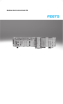
2. Connect the DeviceNet drop line to the ten-pin linear plug by matching the
wire insulation colors to the colors shown on the label:
+24V Red
Can_H White
Drain/Shield
Can_L Blue
+24V Return Black
Ten-pin
linear plug
Red
White
Shield
Blue
Black
Front of module
3. Locate the DeviceNet port connector on the front of the module.
4. Insert the ten-pin linear plug into the DeviceNet port connector.
Ten-pin
linear plug
DeviceNet port
connector
DeviceNet drop line
You have installed and wired your module. To operate the module
you must apply power and then configure and program the SLC processor to
communicate with it. We describe how to do this in the next three sections.
Publication 1747-IN058C-EN-P - May 2002
12
1747-SDN DeviceNet Scanner Module
Apply Chassis Power
When you apply chassis power, the module numeric indicators cycle through the
following displays:
DeviceNet
STATUS
MODULE
NET
Module
numeric
indicators
ADDRESS/ERROR
1. Seven-segment lamp test (88)
2. Firmware major revision (01 through 7F hexadecimal)
3. Firmware minor revision (01 through FF hexadecimal)
4. Baud rate (indicates 00 for the default of 125, 01 for 250 or
02 for 500 Kbits/s)
5. Node address (00 to 63 with 63 as the default)
Use the RSNetWorx for DeviceNet software to change the baud rate and node
address.
Refer to the Numeric Code Display Summary table on page 36 for a complete listing
of numeric displays.
Understand the Data Organization of the Module
The module has four data areas to transfer data, status and command information
between the module and the processor:
•
•
•
•
SLC
SLC
SLC
SLC
input image table
output image table
M1 file
M0 file
Publication 1747-IN058C-EN-P - May 2002
1747-SDN DeviceNet Scanner Module
13
Input and Output Image Tables
The following table describes the mapping of the 1747-SDN input and output image
tables and the M1 and M0 files.
Words
SLC Input Image
Words
SLC Output Image
0
Status
0
Command
1-31
DeviceNet Input Data (31 words)
1-31
DeviceNet Output Data (31
words)
Words
SLC M1 File
Words
SLC M0 File
0-149
DeviceNet Input Data (150 words)
0–149
DeviceNet Output Data
(150 words)
150-205
Reserved (56 words)
150–223
206-209
Device Active Table (4 words)
Reserved
(74 words)
210
Node Address/Status Indicator
(1 word)
211
Scan Counter (1 word)
212-215
Device Idle Table (4 words)
216-219
Device Failure Table (4 words)
220-223
Auto Verify Failure Table
(4 words)
224-255
Explicit Message Program Control (32
words)
224–255
Explicit Message Program Control
(32 words)
256-394
Pass-Through (139 words)
256-394
Pass-Through (139 words)
Use RSLogix 500 Software to Configure M0-M1 Files
To enable pass-through capability of the scanner module, you must configure the
M0 and M1 files associated with the 1747-SDN module to 395 words. If you do not
want to use pass-through, configure the files to the default length of 256 words.
ATTENTION
The pass-through feature is not intended to replace a
1770-KFD, PCD, PCID, or PCIDS connection to the network:
!
• Pass-through is intended only for fine tuning and
adjustment of your network devices. Do not attempt to
configure your entire network using a pass-through
driver or a time-out may occur.
• The pass-through method is not suitable for real time
monitoring of your network devices.
Publication 1747-IN058C-EN-P - May 2002
14
1747-SDN DeviceNet Scanner Module
Use the following procedure to configure the 1747-SDN’s M0 and M1 files using
RSLogix 500 software.
1. Run RSLogix 500 and go offline to the SLC 500 processor.
2. Under the Controller folder in the Project window, double-click on
IO Configuration.
The I/O Configuration window will open.
3. Click on the Read I/O Config. button to upload the I/O configuration from
the processor.
4. Double-click on the 1747-SDN module.
Publication 1747-IN058C-EN-P - May 2002
1747-SDN DeviceNet Scanner Module
15
The Advanced I/O Configuration window will open.
5. Set the MO Length and the M1 Length to one of the following:
a. 256 for 1747-SDN firmware prior to 4.015 for no pass-through support
b. 361 for 1747-SDN firmware 4.015-5.001 for pass-through support
c. 395 for 1747-SDN firmware 6.001 or higher for improved pass-through
support
6. Click on the OK button.
7. Download the changes to the processor.
IMPORTANT
The SLC 500 must be placed in Run mode at least one time after
downloading the M0/M1configuration to enable 1747-SDN
pass-through transactions.
For more information on how to:
• configure your module for DeviceNet operation
• map data from DeviceNet nodes to M1, M0, input and output image files,
refer to the Getting Results with RSLogix 500 (publication number
9939-RL50GR) and the 1747-SDN Scanner User Manual (publication number
1747-6.5.5).
Publication 1747-IN058C-EN-P - May 2002
16
1747-SDN DeviceNet Scanner Module
Program the Module Using the SLC M0 and M1 Files
The M0 and M1 files are data files that reside in the module. There is no image for
these files in the processor memory. The M0 file is a module output file and the M1
file is a module input file. Both M0 and M1 files are read/write files.
M0 and M1 files can be addressed in your ladder program and they can also be
acted upon by the module, independent of the processor scan.
IMPORTANT
During the processor scan, M0 and M1 data can be changed
by the processor according to ladder diagram instructions
addressing the M0 and M1 files. During the same scan, the
module can change M0 and M1 data, independent of the rung
logic applied during the scan.
Address the M0-M1 Files
The addressing format for M0 and M1 files is as follows:
Mf:S.w/b
Where M = module
f = file (0 or 1)
S = slot (1-30)
w = word (0-maximum supplied by the module)
b = bit (0-15)
When You Cannot Use M0-M1 Data File Addresses
You can use M0 and M1 data file addresses in all instructions except the OSR
instruction and the instruction parameters below.
Instruction
Parameter (characterized by file indicator #)
BSL
BSR
File (bit array)
SQO
SQC
SQL
File (sequencer file)
LFL
LFU
LIFO (stack)
FFL
FFU
FIFO (stack)
Publication 1747-IN058C-EN-P - May 2002
1747-SDN DeviceNet Scanner Module
17
Monitor Bit Instructions with M0 or M1 Addresses
When you monitor a ladder program in the Run or Test mode, the following bit
instructions, addressed to an M0 or M1 file, are indicated as false regardless of their
actual true/false logical state.
Mf:S.w
] [
b
XIC
Mf:S.w
]/[
b
XIO
Mf:S.w
( )
b
OTE
Mf:S.w
(U)
b
Mf:S.w
(L)
b
OTL
OTU
To show the state of the M0 or M1 addressed bit, transfer the state to an internal
processor bit. This is illustrated below, where an internal processor bit is used to
indicate the true/false state of a rung.
B3
] [
0
B3
] [
1
EQU
EQUAL
Source A
N7:12
Source B
N7:3
M0:3.0
( )
1
This rung does not show its true rung state because the EQU instruction is
always shown as true and the M0 instruction is always shown as false.
B3
] [
0
B3
] [
1
EQU
EQUAL
Source A
N7:12
Source B
N7:3
B3
( )
2
M0:3.0
( )
1
OTE instruction B3/2 has been added to the rung. This instruction shows the true or
false state of the rung.
Transfer Data Between Processor Files and M0 or M1 Files
The processor does not contain an image of the M0 or M1 file so you must edit and
monitor M0 and M1 file data via instructions in your ladder program. For example,
you can copy a block of data from a processor data file to an M0 or M1 data file or
vice versa using the COP (copy) instruction in your ladder program.
Publication 1747-IN058C-EN-P - May 2002
18
1747-SDN DeviceNet Scanner Module
The COP instructions below copy data from a processor bit file and integer file to
an M0 file.
S:1
] [
15
First scan bit. It makes this rung
true only for the first scan after
entering Run mode.
COP
COPY FILE
Source
Dest
Length
#B3:0
M0:1.0
16
COP
COPY FILE
Source
Dest
Length
#N7:0
#M0:1.16
27
The COP instruction below copies six words of data from an M1 data file in a
module positioned in slot four to an integer file (N1:0). This technique is used to
monitor the contents of an M0 or M1 data file indirectly, in a processor data file. An
update of these six words is made for each SLC program scan.
COP
COPY FILE
Source
Dest
Length
Publication 1747-IN058C-EN-P - May 2002
#M1:4.3
#N10:0
6
1747-SDN DeviceNet Scanner Module
19
Reduce Scan Time
To reduce processor scan time, use discretion when you use
instructions addressing the M0 or M1 files. For example, XIC
instruction M1:2.1/1 is used in rungs 1 and 2 below, adding
approximately 2 ms to the scan time if you are using a 5/02,
Series B processor.
TIP
1
M1:2.1
] [
1
2
B3
] [
12
B3
( )
10
M1:2.1
] [
1
B3
( )
14
XIC instructions in rungs 1 and 2 are addressed to the M1 data file. Each of
these instructions adds approximately 1ms to the scan time (5/02, Series B
processor)
In the equivalent rungs below, XIC instruction M1:2.1/1 is used only in rung 1,
reducing the scan time by approximately 1 ms.
1
M1:2.1
] [
1
2
B3
] [
12
B3
( )
10
B3
] [
10
B3
( )
14
These rungs provide equivalent operation to those of the previous diagram by
substituting XIC instruction B3/10 for XIC instruction M1:2.1/1 in rung 2.
Scan time is reduced by approximately 1ms (5/02 Series B processor).
The first two ladder diagrams in the last section illustrate a technique you use to
capture and use M0 or M1 data as it exists at a specific time. In the first diagram, bit
M1:2.1/1 could change state between rungs 1 and 2. This could interfere with the
logic applied in rung 2. The second diagram avoids the problem. If rung 1 is true,
bit B3/10 captures this information and places it in rung 2.
The following diagram illustrates another economizing technique. The COP
instruction addresses an M1 file, adding approximately 4.29 ms to the scan time if
you are using a 5/02, Series B processor. You can save scan time by making this
rung true only periodically. For example, you can use a clock bit S:4/8 (clock bits
are discussed in the programming manual).
Publication 1747-IN058C-EN-P - May 2002
20
1747-SDN DeviceNet Scanner Module
A rung such as this might be used when you want to monitor the contents of the
M1 file, but monitoring need not be continuous.
S:4/8 causes the M1:4.3 file
to update the N10:0 file
every 2.56 seconds.
S:4
] [
8
B11
[OSR]
0
COP
COPY FILE
Source
Dest
Length
#M1:4.3
#N10:0
6
In this example, a COP instruction can be used to monitor the contents of an M1
file. When the instruction goes true, the six words of data in file #M1:4.3 is captured
as it exists at that time and placed in file #N10:0. All subsequent logic should
address the data in #N10:0. The data will be consistent and it shortens scan time by
eliminating reads to the module each time an M0 or M1 address is encountered in
the program.
Upload Input Data from the Module to the SLC Processor
The SLC 500 processor reads input data from the module using two methods:
• input image table
• M1 file transfer
Input Image Table
The input image table is a 32-word table for the module slot that is updated by the
processor with each program scan. The first word (word 0) is reserved for the
module status register. The remaining 31 words can be used to transfer DeviceNet
input data to the SLC input image table. The addressing format is:
I:S.w/b
Where S = slot
w = word (0-31)
b = bit (0-15)
Module Status Register
The module status register is located at word 0 in the input image area for the slot.
Bits 0–5 echo back to the processor, the current state of bits 0–5 of the module
command register. The echoes verify that the commands were executed. The
module sets the remaining bits when it detects a problem. The bits latch in the ON
state until the problem clears. Bits 6 and 8 indicate that you should read the device
failure table for more specific information about which devices failed.
Publication 1747-IN058C-EN-P - May 2002
1747-SDN DeviceNet Scanner Module
21
You can use bit 6 to keep the communication port in the Idle mode until the bit
clears. When the bit clears, this indicates that all devices in the scanner’s scan list
are up and available. When the devices are available, you can put the port in Run
mode. If a device failure is detected, you can put the communication into the Idle
mode, so that all output devices go to a safe state.
The SLC program can monitor the bits in the module status register and set the
appropriate bits of the module command register to automatically control the
operating mode of the module should a device failure occur.
Status Word I:s.0
Bit
Operating Mode
0
1 = Run mode, 0 = Idle mode
(echoed from the module
command register)
Operating Mode Description
Run
The scanner module maps output data from its scanner output table (M0) and
discrete outputs to each device on the network. Inputs are received and mapped
into the scanner input table (M1) and discrete inputs. Outputs on the network are
under SLC program control.
Idle
The scanner does not map output data to the devices, but keeps network
connections to devices open so device failures can be detected. Input data is
returned from devices, and mapped into the scanner input table (M1) and the
discrete inputs. Outputs on the network are not under program control and will be
in their configured ‘Idle state.’ The scanner must be put into this mode to perform
offline configuration of the scanner database tables.
1
1 = fault network (echoed
from the module command
register)
2
Reserved
3
Reserved
4
1 = disable network (echoed
from the module command
register)
5
Reserved
6
1 = device failure (at least
one device failed)
7
Reserved
8
1 = autoverify failure (at
least one device has failed
auto verify)
9
Reserved
10
1 = communication failure
Fault Network
The scanner has stopped communicating with devices on the network. No outputs
or inputs are mapped. Outputs on the network are not under program control.
If scanner was in Run mode, devices will go to their fault state.
Disable Network
The DeviceNet channel is disabled for communication. No communication may
occur over this channel. Outputs on the network are not under program control.
If scanner was in Run mode, devices will go to their fault state.
Device Failure
One or more of the devices in the scanner’s scan list has failed to communicate
with the scanner.
Autoverify Failure
One or more of the devices in the scanner’s scan list is returning an incorrect
number of bytes of data in response to a connection establishment, according to
the information stored in the scanner’s scan list.
Communications Failure
There is no communication on the port.
Publication 1747-IN058C-EN-P - May 2002
22
1747-SDN DeviceNet Scanner Module
Status Word I:s.0
Operating Mode Description
Bit
Operating Mode
11
Reserved
12
1 = duplicate node address
failure
13
Reserved
14
Reserved
15
1 = Explicit Message
Program Control
Response available in M1
file.
0 = Empty
Duplicate Node Address Failure
There is another node with the same address as the scanner on the network.
Explicit Message Program Control
A response to a previously sent Explicit Message is now available to be
read/interpreted by the ladder program.
SLC M1 File
The SLC M1 file is a 256 word file that can be used to transfer a large quantity of
information to the module with a single SLC instruction.
IMPORTANT
Transferring data using this file takes more time than using the
input image table.
The first 150 words are used for data transfer from the module. The remaining 106
words are reserved for:
•
•
•
•
•
•
•
device active table
node status
scan counter
device idle table
device failure table
auto verify table
explicit message program control
For a details on the mapping of input and output image tables, refer to page 13.
Device Active Table
Words 206 through 209 in the M1 file are used for the Device Active Table. The
scanner assigns one bit in consecutive order to consecutive device addresses
starting at node 0 at M1.S.206/0. If a bit is set, it indicates that the node is in the
scanner’s scan list and has successfully communicated with the scanner module.
The bit is reset if the scanner tries to communicate to the node but the node has
gone offline.
Publication 1747-IN058C-EN-P - May 2002
1747-SDN DeviceNet Scanner Module
23
Node Address/Status Indicator
Word 210 is used for node address and scanner diagnostic information displayed in
numeric codes. The high byte is the node address and the low byte is the status for
that node. These codes and their descriptions are listed on page 36.
Scan Counter
Word 211 is used for the module scan counter. The module increments this counter
whenever a scan of the DeviceNet devices is completed. The counter rolls over
when it reaches a maximum value of 65535. It is located at M1:S.211.
Device Idle Table
Words 212 through 215 in the M1 file are used for the device idle table. This table
indicates that there are devices on the network in Idle mode. The module tracks
devices in Idle mode by assigning one of the 64 bits in the table to each device on
the network. The bits are assigned in consecutive order to consecutive device
addresses starting at mode 0 at M1.S.212/0.
Device Failure Table
Words 216 through 219 in the M1 file are used for the device failure table. This table
indicates communication failures of devices on the network. The module tracks
device failures by assigning one of the 64 bits in the table to each device on the
network. The bits are assigned in consecutive order to consecutive device
addresses starting at mode 0 at M1.S.216/0.
Auto Verify Failure Table
Words 220 through 223 in the M1 file are used for the auto verify failure table.
The auto verify failure table is used to verify that data size received from the device
matches the setting in the scanner’s scanlist entry for that node. This check occurs
at connection establishment time. The module tracks auto verify failures by
assigning one of the 64 bits in the table to each device on the network. The bits are
assigned in consecutive order to consecutive device addresses starting with node 0
at M1:S.220/0. If the bit is set, the corresponding node has failed to verify.
Publication 1747-IN058C-EN-P - May 2002
24
1747-SDN DeviceNet Scanner Module
Explicit Message Program Control
Words 224 through 255 are used for Explicit Message Program Control. Use this
feature to configure device parameters on your DeviceNet network via the M0 and
M1 files in the SLC processor that is controlling these devices. This feature is
described in detail on page 27.
Download Output Data to the Module
The SLC 500 processor writes output data to the module using two methods:
• output image table
• M0 file transfer
Output Image Table
The output image table is a 32-word table for the module slot that is updated from
the processor with each program scan. The first word (word 0) of this table is
reserved for the module command register. The remaining 31 words can be used to
transfer data from the SLC output table to the DeviceNet nodes.
Module Command Register
The module command register is located at word 0 in the output image area for the
slot. To execute a command, set the appropriate bits in the module command word
using SLC ladder instructions.
Publication 1747-IN058C-EN-P - May 2002
1747-SDN DeviceNet Scanner Module
25
The following table describes the functionality of the command register bits.
Command Word 0:S.0
Bit
Operating Mode
0
1 = Run mode, 0 = Idle
mode
Operating Mode Description
Run
The scanner module maps output data from its scanner output table (M0) and
discrete outputs to each device on the network. Inputs are received and mapped
into the scanner input table (M1) and discrete inputs. Outputs on the network are
under SLC program control.
Idle
The scanner does not map output data to the devices, but keeps network
connections to devices open so device failures can be detected. Input data is
returned from devices, and mapped into the scanner input table (M1) and the
discrete inputs. Outputs on the network are not under program control and will be
in their configured ‘idle state.’ The scanner is put into this mode to perform online
configuration of the scanner database tables.
1
1 = fault network
Fault Network
The scanner stops communicating with devices on the network. No outputs or
inputs are mapped. Outputs on the network are not under program control.
If scanner was in Run mode, devices will go to their fault state.
2
1 = restore to factory
defaults/flush memory
Restore to Factory Defaults/Flush Memory
The scanner may receive a scan list or configuration that causes inappropriate
scanner behavior. It may be necessary to restore to the scanner module’s factory
defaults to recover from this state. This procedure is described below.
3
Reserved1
4
1 = disable network
5
Reserved1
6
1 = halt scanner
Halt Scanner
All scanner operations stop when this command is issued. No communications
occur over either DeviceNet port. No M-file or discrete I/O mapping occurs.
Outputs on the network are not under program control. If scanner was in Run
mode, devices will go to their fault state.
7
1 = reboot
Reboot
This command causes the scanner to reset as though power had been cycled.
When this command is issued, all scanner communication stops for the duration of
the scanner’s initialization sequence. Outputs on the network are no longer under
program control. If scanner was in Run mode, devices will go to their fault state.
8-15
Reserved1
1
Disable Network
The DeviceNet channel is disabled for communication. No communication may
occur over this channel. Outputs on the network are not under program control.
If scanner was in Run mode, devices will go to their fault state.
All reserve bits must be set to zero or improper operation may result.
Publication 1747-IN058C-EN-P - May 2002
26
1747-SDN DeviceNet Scanner Module
Restore Factory Default Settings/Flush Memory
To restore the scanner module’s factory default settings, follow these procedures:
1. While the SLC processor in Program mode, clear the module command word
0 and set bit 2 of word 0 for the scanner module to “ON” or 1 (starting with
bit 0 going from right to left, this is the third bit).
IMPORTANT
If other bits in the module command word are set, then the
scanner module will generate an error.
2. Set bit 0 of word 0 for the scanner module to “OFF” or 0.
3. On the SLC processor, cycle the keyswitch from Program mode to Run mode
then back to Program mode.
IMPORTANT
The ladder logic may set bit 0 of word 0 for the scanner
module. If this happens, then you must disable or delete this
rung from the ladder program.
4. When the code E9 is displayed on the Address/Error LED display the default
settings have been restored.
5. Set bit 2 of word 0 for the scanner module to “OFF” or 0.
6. Cycle power to the 1746 chassis to restore normal operation to the scanner
module.
The scanner module will now have its factory default settings:
- node 63
- 125 K baud
- no scanlist
Publication 1747-IN058C-EN-P - May 2002
1747-SDN DeviceNet Scanner Module
27
SLC M0 File
The SLC M0 file is a 256 word file that can be used to transfer a large quantity of
information to the module with a single SLC instruction. Transferring data using this
file can take several scans and more time than using the output image table.
The first 150 words are used for sending data to DeviceNet nodes. The next 74
words are reserved for future use, the next 32 words are used for explicit message
program control and the final 139 words are used for pass-through.
For a detailed description of the mapping of input and output image tables, refer to
page 13.
Using Explicit Message Program Control
Use the Explicit Message Program Control feature to configure device parameters
on your DeviceNet network via the M0 and M1 files.
Use the Explicit Message Program Control feature to:
• transmit configuration data from your scanner module to its slave devices on
your DeviceNet network
• receive status and diagnostics from these devices on your DeviceNet
network
• make runtime adjustments to device parameters according to changing
conditions detected by your processor
Publication 1747-IN058C-EN-P - May 2002
28
1747-SDN DeviceNet Scanner Module
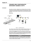
How the Explicit Message Program Control Feature Works
M0 file transfer (including words 224-255)
(sent from processor to scanner module)
4
M1 file transfer (including words 224-255)
(sent from scanner module to processor)
5
M1 file transfer
is completed. TXIDs
are deleted and can
be reused.
Explicit Message - A message used to transmit
commands, data, requests for data or responses.
The message is sent from a client on the DeviceNet
network to a server on that network.
Request - An explicit message sent by a client
to a server requesting the server to perform
a function.
Response - An explicit message sent by a server to
a client in response to the client’s request. For every
request issued, there is a response.
Master’s Explicit
Request
DeviceNet trunk line
DeviceNet
drop line
Slave’s Explicit
Request
1203-GK5
Communication
Adapter
1305 AC
Drive
1. Format an M0 file transfer in the processor to send an Explicit Message
Request to the scanner module (download).
2. The scanner module transmits the Explicit Message Request to the slave
device over the DeviceNet network.
3. The slave device transmits the Explicit Message Response back to the
scanner and is queued into a file transfer buffer.
4. The processor uses an M1 file transfer to retrieve the Explicit Message
Response from the scanner’s buffer (upload).
5. Format an M0 file transfer with a Delete Response Command and the current
transaction ID read in step 4. The transaction IDs are deleted and can be
reused.
The scanner module requires a precisely-formatted M0 and M1 file transfer size of
32 words including words 224–255. The scanner module uses the file memory
content as a client/server request.
Publication 1747-IN058C-EN-P - May 2002
1747-SDN DeviceNet Scanner Module
29
How to Format the Explicit Message Transaction Block
Up to ten 32-word transaction blocks may be queued within the scanner module
for Explicit Message Program Control. The transaction blocks accommodate both
the download of Explicit Message Requests and the upload of Explicit Message
Responses.
The scanner module can accommodate one request or response for each
transaction block. You must format each transaction block as shown in the
following figure:
15
Transaction
Header
(3 words)
0
TXID
cmd/status
word 224
port
size
word 225
service
MAC ID
word 226
Transaction Body
(29 words)
word 255
One word = two bytes = 16 bits
The transaction block is divided into two parts:
• transaction header – contains information that identifies the transaction to
the scanner and processor
• transaction body – in a request, this contains the DeviceNet Class,
Instance, Attribute and Service Data portion of the transaction. In a response,
this contains only the response message.
Each of the data attributes in the transaction header are one byte in length:
• command/status – for each download, you assign a command code to
instruct the scanner how to administer the request:
Command Code
Description
0
Ignore transaction block (block empty)
1
Execute this transaction block
2
Get status of transaction TXID
3
Reset all client/server transactions
4
Delete transaction from response queue
5–255
Reserved
Publication 1747-IN058C-EN-P - May 2002
30
1747-SDN DeviceNet Scanner Module
For each upload, the status code provides the processor with status on the device
and its response:
Status Code
Description
0
Ignore transaction block (block empty)
1
Transaction completed successfully
2
Transaction in progress (not ready)
3
Error – slave not in scan list
4
Error – slave offline
5
Error – DeviceNet port disabled/offline
6
Error – transaction TXID unknown
7
Error – slave not responding to explicit request
8
Error – Invalid command code
9
Error – Scanner out of buffers
10
Error – Other Client/server transaction in progress
11
Error – could not connect to slave device
12
Error – response data too large for block
13
Error – invalid port
14
Error – invalid size specified
15
Error – connection busy
16–255
Reserved
• TXID (transaction ID) – when you create and download a request to the
scanner, the processor’s ladder logic program assigns a TXID to the
transaction. This is a one-byte integer in the range of 1 to 255. The scanner
uses this value to track the transaction to completion, and returns the value
with the response that matches the request downloaded by the processor.
The ladder logic program monitors rollover and usage of TXID values.
15
Transaction
Header
(3 words)
TXID
port
service
0
cmd/status word 224
word 225
size
word
226
MAC ID
Transaction Body
(29 words)
word 255
One word = two bytes = 16 bits
• size – the size of the transaction body in bytes. The transaction body can be
as many as 29 words (58 bytes) in length. If the size exceeds 29 words, an
error code will be returned.
• port – the DeviceNet port (zero) where the transaction is routed.
Publication 1747-IN058C-EN-P - May 2002
1747-SDN DeviceNet Scanner Module
31
• MAC ID (node address) – the DeviceNet network address of the slave
device where the transaction is sent. This value can range from 0 to 63.
The port and MAC ID attributes coupled together identify the target slave
device. The slave device must be listed in the scanner module’s scan list and
be online for the Explicit Message transaction to be completed successfully.
• service – for each Explicit Message Request and Response, the service
attribute contains the service request and response codes that match the
corresponding request for the TXID.
The following figure describes the format and mapping of transaction blocks for
request and response messages in the scanner module:
Format of 32-word M0 Transfer File
for Explicit Message Request
0
15
cmd/status word 224
TXID
Transaction
Header
word 225
port
size
(3 words)
service
word 226
MAC ID
Class
Instance
Attribute (optional)
Transaction
#1
Transaction
Header
(3 words)
Format of 32-word M1 Transfer File
for Explicit Message Response
0
15
cmd/status word 224
TXID
port
size
word 225
service
MAC ID
word 226
Service Response Data Transaction
#1
Service Data
word 255
word 255
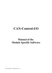
How the Processor and Scanner Module Manage Messages
File transfer operations between the processor and the scanner always originate in
the processor. The scanner module can only wait for the processor to download a
transaction block to the module or request an upload of a transaction block from
the module.
Once an Explicit Message Request transaction block is downloaded to the scanner
module, a ladder logic program in the processor polls the scanner module for the
transaction block containing the Explicit Message Response for that request. This is
done by the processor with an M1 file transfer on the scanner module.
Depending on the network load, the scanner could take a few seconds to complete
the request. When a response is loaded, bit 15 of the module status register is set to
1. The program may have to poll the scanner module a number of times before the
scanner returns a Response Transaction Block.
The scanner module recognizes I/O data and control as higher priorities over
explicit messaging on DeviceNet.
Publication 1747-IN058C-EN-P - May 2002
32
1747-SDN DeviceNet Scanner Module
Message lengths and slave device types impact transaction message completion
times. If the processor has queued multiple Explicit Message Transactions to the
scanner module for multiple slave devices, the transactions with the slaves may not
complete in the order in which the requests were received. The slave responses are
queued to the 32 word M1 file transfer in the order in which they are received.
As response transaction blocks are uploaded, the processor’s program matches the
responses to the requests using the TXID field.
DeviceNet Network
Scanner Module
Processor
M0 file transfer
Request
Transaction
Block
Request
Transaction
Blocks
Scanner
Request
Queue
Process Requests
and Responses
Ladder Scans
DeviceNet
Explicit Message
Requests and
Responses
Slave
Device
Done or
Error-detached
Response
Transaction
Block
Response
Transaction
Blocks
Scanner
Response
Queue
M1 file transfer
Explicit Message Program Control Limitations
• The processor is always the DeviceNet client and the slave is always the
DeviceNet server.
• A maximum of ten Explicit Message Request Transaction Blocks with the
execute command can be queued to the scanner module at any time. For
example, ten M0 file transfers containing one transactions each, can be
queued at any time. The scanner module receives and deletes any additional
client/server requests with the execute command over the maximum of ten.
As transactions are removed from the queue and response transaction blocks are
returned to the processor, additional transaction blocks can be issued in their place,
as long as the total does not exceed ten.
• The scanner module supports one transaction block per upload and
download.
• Request Transaction Blocks can only be queued for slave devices of the
scanner module and must appear in the scanner module’s scan list.
Publication 1747-IN058C-EN-P - May 2002
1747-SDN DeviceNet Scanner Module
33
• If a slave device is not communicating at the time the scanner module
processes its Request Transaction Block, the scanner module will return an
error status for that transaction.
• Check documentation of destination device for specifics concerning services
supported and Class Instance Attribute information. At a minimum, the
scanner module supports the following DeviceNet services in Request
Transaction Blocks:
Service Name:
Service Code:
Example:
Get_Attribute_Single
0E hex
Upload a single parameter value from a
device
Set_Attribute_Single
10 hex
Download a single parameter value to a
device
Get_Attribute_All
01 hex
Upload all parameter values from a device
Set_Attribute_All
02 hex
Download all parameter values to a device
• All transaction blocks are processed, therefore, an unused transaction block
must be left blank.
• Client/Server commands and requests with transaction IDs that are in use are
ignored by the scanner module.
• If a slave device returns a DeviceNet error in response to the request
downloaded from the processor, the scanner recognizes the error as a
successful transaction (status code =1).
Publication 1747-IN058C-EN-P - May 2002
34
1747-SDN DeviceNet Scanner Module
A failure to respond to the request within the number of retries or timeout period
specified for the Explicit Message Connection is recognized by the scanner module
as an error. The error code is returned in the status attribute of the transaction
header.
Explicit Messaging Error Codes
Error codes have two bytes of data. The first byte is a General Error Code and the
second is an optional Additional Code Field that may contain additional information
about the error. If this field is unused, the value 0FFH is shown. The following table
describes explicit messaging error codes.
Numeric
Code:
Name:
Description:
02H
Resource unavailable
A needed resource was not available
08H
Service unsupported
Service is not defined or implemented for this
class/instance
09H
Invalid attribute value
Data is invalid for the specified attribute
0BH
Already in requested state
Object is in the requested state - redundant request
0CH
Object state conflict
Not allowed with object in present state
0EH
Attribute cannot be set
Read-only attribute
0FH
Privilege violation
A permission/privilege check failed
10H
Device state conflict
Not allowed with device in present state
11H
Reply too big
Reply larger than buffer allocated when connection
was established
13H
Too little data
Request included insufficient data
14H
Attribute not supported
Attribute number is incorrect
15H
Too much data
Request included extra data
16H
Object does not exist
Class/instance numbers are incorrect
18H
No stored attribute data
Attribute data was not saved prior to this request
19H
Store operation failure
Attribute data was not successfully saved
1FH
Vendor-specific error
Second byte may offer details - refer to vendor
documentation
20H
Invalid parameter
Parameter associated with request is invalid
D0H
Reserved and service-specific
errors
Used only when none of the standard error codes
supplemented by the second byte accurately describes
the problem.
FFH
Publication 1747-IN058C-EN-P - May 2002
1747-SDN DeviceNet Scanner Module
35
Troubleshoot the Module and Network
The bicolor (green/red) module status indicator (MODULE) located on the front of
your module displays module status. It indicates whether the module has power
and is functioning properly.
Module Status Troubleshooting
If the MODULE
indicator is:
Then:
Take this action:
Off
There is no power applied to the module. Verify power connections and apply power.
Green
The module is operating normally.
No action required.
Flashing Green
The module is not configured.
Configure the module.
Flashing Red
There is an invalid configuration.
Check configuration setup.
Red
The module has an unrecoverable fault.
Replace the module.
The DeviceNet channel has a bicolor (green/red) network status indicator (NET).
The following table provides troubleshooting information about the DeviceNet
channel communication link.
DeviceNet Channel Communications Troubleshooting
If the NET Then
indicator
is:
Which indicates
Take this action
Off
The device has no power or the
The channel is disabled
channel is disabled for communication for DeviceNet
due to bus off condition, loss of
communication.
network power, or has been
intentionally disabled.
Green
Normal operation.
All slave devices in the None.
scan list table are
communicating
normally with the
module.
Flashing
Green
The two-digit numeric display for the
channel indicates an error code that
provides more information about the
condition of the channel.
The channel is enabled Configure the scan list table for the channel to
but no communication add devices.
is occurring.
Flashing
Red
The two-digit numeric display for the
channel displays an error code that
provides more information about the
condition of the channel.
At least one of the
Examine the failed device and the scan list table
slave devices in the
for accuracy.
module’s scan list table
has failed to
communicate with the
module.
Red
The module may be
The communications channel has
failed. The two digit numeric display defective.
for the channel displays an error code
that provides more information about
the condition of the channel.
Power-up the module, provide network power to
the channel, and be sure the channel is enabled
in both the module configuration table and the
module command word.
Reset module. If failures continue, replace
module.
Publication 1747-IN058C-EN-P - May 2002
36
1747-SDN DeviceNet Scanner Module
Numeric Codes and Descriptions
Your module uses numeric displays to indicate diagnostic information about the
status of your module. The display flashes at 1 second intervals. The following table
summarizes the meanings of the numeric codes.
Numeric Code Display Summary
Numeric Description
Code
Take this action
0 - 63
Normal operation. The numeric display indicates None.
the 1747-SDN’s node address on the DeviceNet
network.
70
Module failed Duplicate Node Address check.
Change the module channel address to another
available one. The node address you selected is
71
Illegal data in scan list table (node number
alternately flashes).
Reconfigure the scan list table and remove any
illegal data.
72
Slave device stopped communicating (node
number alternately flashes).
Inspect the field devices and verify connections.
73
Device’s identity information does not match
electronic key in scan list table entry.
Verify that the correct device is at this node
number. Make sure that the device at the scrolling
node address matches the desired electronic key
(vendor, product code, product type, etc.).
74
Data overrun on port detected.
Modify your configuration and check for invalid
data. Check network communication traffic.
75
No traffic from other modules detected on the
network.
Check the network configuration. (Scanlist may be
empty.)
76
No direct network traffic for module detected.
None. The module hears other network
communication.
77
Data size expected by the device does not match Reconfigure your module for the correct transmit
scan list entry.
and receive data sizes.
78
Slave device in scan list table does not exist.
Add the device to the network, or delete the scan
list entry for that device.
79
Module has failed to transmit a message.
Make sure that your module is connected to a valid
network.
Check for disconnected cables.
80
Module is in Idle mode.
Put controller in Run mode. Enable Run bit in
module command register.
81
Module is in FAULT mode.
Check Module Command Register for fault bit set.
82
Error detected in sequence of fragmented I/O
messages from device.
Check scan list table entry for slave device to make
sure that input and output data lengths are correct.
Check slave device configuration.
83
Slave device is returning error responses when
module attempts to communicate with it.
Check accuracy of scan list table entry. Check
slave device configuration. Slave device may be in
another master’s scan list. Reboot slave device.
84
Module is initializing the DeviceNet network.
None. This code clears itself once module
attempts to initialize all slave devices on the
network.
already in use on that channel.
Publication 1747-IN058C-EN-P - May 2002
1747-SDN DeviceNet Scanner Module
Numeric Description
Code
37
Take this action
• Slave device is transmitting incorrect
length data.
• Verify device is not configured for
variable poll connection size.
• Try replacing the device.
85
Data size was incorrect for this device at
runtime.
86
Device is producing zero length data (idle state) Check device configuration and slave node status.
while module is in Run Mode.
87
The primary owner has not allocated the slave.
88
The connection choices (polled, strobed, etc.)
Reconfigure the shared input only connection’s
between the primary connection and the shared choice(s) to be the same as, or a subset of, the
input only connection do not match.
primary connection’s choice(s).
Put the primary owner on line.
89
Slave device initialization using Auto Device
Replacement parameters failed.
90
User has disabled communication port.
Check Module Command Register for DISABLE bit
set.
91
Bus-off condition detected on comm port.
Module is detecting communication errors.
Check DeviceNet connections and physical media
integrity. Check system for failed slave devices or
other possible sources of network interference.
92
No network power detected on communication
port.
Provide network power. Make sure that module
drop cable is providing network power to module
comm port.
95
Application FLASH update in progress.
None. Do not disconnect the module while
application FLASH is in progress. You will lose any
existing data in the module’s memory.
• Put the slave device into configurable
mode.
• Check the slave’s EDS file, if the slave is
configured offline.
• Check to see if the slave device has been
replaced with an incompatible device.
97
Module operation halted by user command.
Check Module Command Register for HALT bit set.
98
Unrecoverable firmware failure.
Service or replace your module.
99
Unrecoverable hardware failure.
Service or replace your module.
E2
RAM Test Failure
Service or replace your module.
E4
Lost power during FLASH upgrade
Service or replace your module.
E5
No boot or main code
Service or replace your module.
E9
Module memory has been flushed for factory
default settings.
Cycle module power to recover.
Publication 1747-IN058C-EN-P - May 2002
38
1747-SDN DeviceNet Scanner Module
The following information applies when
operating this equipment in hazardous
locations:
Informations sur l’utilisation de cet équipement
en environnements dangereux :
Products marked “CL I, DIV 2, GP A, B, C, D” are
suitable for use in Class I Division 2 Groups A, B, C,
D, Hazardous Locations and nonhazardous locations
only. Each product is supplied with markings on the
rating nameplate indicating the hazardous location
temperature code. When combining products within
a system, the most adverse temperature code (lowest
“T” number) may be used to help determine the
overall temperature code of the system.
Combinations of equipment in your system are
subject to investigation by the local Authority Having
Jurisdiction at the time of installation.
Les produits marqués "CL I, DIV 2, GP A, B, C, D" ne
conviennent qu’à une utilisation en environnements
de Classe I Division 2 Groupes A, B, C, D dangereux
et non dangereux. Chaque produit est livré avec des
marquages sur sa plaque d’identification qui
indiquent le code de température pour les
environnements dangereux. Lorsque plusieurs
produits sont combinés dans un système, le code de
température le plus défavorable (code de
température le plus faible) peut être utilisé pour
déterminer le code de température global du
système. Les combinaisons d’équipements dans le
système sont sujettes à inspection par les autorités
locales qualifiées au moment de l’installation.
WARNING
!
EXPLOSION HAZARD
• Do not disconnect
equipment unless
power has been
removed or the area is
known to be
nonhazardous.
• Do not disconnect
connections to this
equipment unless
power has been
removed or the area is
known to be
nonhazardous. Secure
any external
connections that mate
to this equipment by
using screws, sliding
latches, threaded
connectors, or other
means provided with
this product.
• Substitution of
components may impair
suitability for Class I,
Division 2.
• If this product contains
batteries, they must
only be changed in an
area known to be
nonhazardous.
Publication 1747-IN058C-EN-P - May 2002
AVERTISSEMENT
!
RISQUE D’EXPLOSION
• Couper le courant ou
s’assurer que
l’environnement est
classé non dangereux
avant de débrancher
l'équipement.
• Couper le courant ou
s'assurer que
l’environnement est
classé non dangereux
avant de débrancher les
connecteurs. Fixer tous
les connecteurs
externes reliés à cet
équipement à l'aide de
vis, loquets coulissants,
connecteurs filetés ou
autres moyens fournis
avec ce produit.
• La substitution de
composants peut rendre
cet équipement
inadapté à une
utilisation en
environnement de
Classe I, Division 2.
• S’assurer que
l’environnement est
classé non dangereux
avant de changer les
piles.
1747-SDN DeviceNet Scanner Module
39
Specifications
Module Location
SLC 5/02 or later chassis
Module Defaults
Node Address – 63
Baud Rate – 125 Kbits/s
Power Consumption
- Backplane Current
- DeviceNet1
5Vdc, 500 mA
24Vdc, 90mA Class 2
Isolation Voltage
Optical Isolation between backplane and DeviceNet channel, tested to
withstand 500Vac for 60 seconds
1 Megohm resistor from DeviceNet channel to chassis
Operating Temperature
IEC 60068-2-1 (Test Ad, Operating Cold),
IEC 60068-2-2 (Test Bd, Operating Dry Heat),
IEC 60068-2-14 (Test Nb, Operating Thermal Shock):
0-60oC (32–140oF)
Storage Temperature
IEC 60068-2-1 (Test Ab, Un-packaged Non-operating Cold),
IEC 60068-2-2 (Test Bc, Un-packaged Non-operating Dry Heat),
IEC 60068-2-14 (Test Na, Un-packaged Non-operating Thermal Shock):
–40 to 85oC (–40 to 185oF)
Relative Humidity
IEC 60068-2-30 (Test Db, Un-packaged Non-operating
Damp Heat):
5–95% non condensing
Vibration
IEC60068-2-6 (Test Fc, Operating):
2g @10–500Hz
Shock
IEC60068-2-27:1987, Test Ea (Unpackaged shock, ES#002)
Operating - 30g
Non-operating - 50g
Emissions
CISPR 11:
Group 1, Class A (with appropriate enclosure)
ESD Immunity
IEC 61000-4-2:
4kV contact discharges
Radiated RF Immunity
IEC 61000-4-3:
10V/m with 1kHz sine-wave 80% AM from 30MHz to 1000Mhz
EFT/B Immunity
IEC 61000-4-4:
+2kV at 5kHz on communications ports
Surge Transient Immunity
IEC 61000-4-5:
+2kV line-earth(CM)
on signal ports
Conducted RF Immunity
IEC 61000-4-6:
10Vrms with 1kHz sine-wave 80%AM from 150kHz
to 30MHz
Enclosure Type Rating
None (open style)
Wiring
- Type
- Category2
1771-CD
2
10-pin Linear Plug
- Torque
- Catalog Number
5-7 pound-inches
1787-PLUG10R
Specifications continued on back page
Publication 1747-IN058C-EN-P - May 2002
Specifications - Continued
Certifications
(when product is marked)
UL
CSA
CSA
CE1
C-Tick3
ODVA
User Manual
UL Listed Industrial Control Equipment
CSA Certified Process Control Equipment
CSA Certified Process Control Equipment for Class I,
Division 2 Group A,B,C,D Hazardous Locations
European Union 89/336/EEC EMC Directive, compliant
with:
EN 50081-2; Industrial Emissions
EN 50082-2; Industrial Immunity
European Union 73/23/EEC LVD Directive, compliant
with:
EN 61131-2; Programmable Controllers
Australian Radiocommunications Act, compliant with:
AS/NZS 2064; Industrial Emissions
ODVA conformance tested to ODVA DeviceNet
specifications
1747–6.5.5
1
To remain compliant with UL/CSA certification, the DeviceNet power supply must meet NEC Class 2
requirements.
2Use this conductor category information for planning conductor routing as described in publication 1770-4.1,
Industrial Automation Wiring and Grounding Guidelines.
3See the Product Certification link at www.ab.com for Declarations of Conformity, Certificates, and other
certification details.
DeviceNet is a trademark of the Open DeviceNet Vendors Association.
SLC, SLC 500, SLC 5/02, SLC 5/03, SLC 5/04, SLC 5/05, RSLinx, RSLogix 500 and RSNetWorx are trademarks of Rockwell
Automation, Inc.
Windows is a trademark of Microsoft Corporation.
Publication 1747-IN058C-EN-P - May 2002
Supersedes Publication 1747-IN058B-EN-P - August 2001
PN 957678-59
Copyright © 2002 Rockwell Automation, Inc. All rights reserved. Printed in the U.S.A.