1
[Sears
OWNERS
MANUAL
AIR
MODEL NOS.
919.174211
919.174310
919.174320
919.174410
IMPORTANT:
Read the Safety
Guidelines Before
Operating
COMPRESSOR
DESCRIPTION
ASSEMBLY
OPERATION
MAINTENANCE
REPAIR PARTS
Record in the spaces provided
below the model number, code
number and manufacturers
number of this air compressor.
The
model number can be found on
the label on the front of the air
tank. The code number can be
found on the foil label on the rear
of the air tank. The manufacturers
number (ASME Code outfits only)
is located on the metal data plate
on the right front of the saddle.
Model No.
Code No.
Mfgs. No.
Motor Mfgo Name
Motor Mfg. No.
Retain these
refeFences.
St-30+14-_
Sears,
Roebuck
and Co,
Chicago,
_L 60684
U.S.Ao
numbers
for
future
2/83
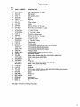
TABLE
OF CONTENTS
Page
WARRANTY
.......................................................
SAFETY GUIDELINES
SPECIFICATION
..............................................
CHART
............................................
GENERAL INFORMATION
GENERAL DESCRIPTION
ASSEMBLY
3
..........................................
OF OPERATION
INSTRUCTIONS
...........................
3
5
6
6
........................................
6
Tools Needed for Assembly ......................................
Attaching Wheels, Handle, Etc ....................................
Installing Regulator .............................................
Start-Up Procedures ............................................
6
6
7
7
OPERATION
.......................................................
Manifold .......................................................
Pressure Switch ................................................
Safety Valve ...................................................
Motor
.........................................................
Pressure Release Valve .........................................
MAINTENANCE
....................................................
Replacing Air Intake Filter .......................................
Checking Safety Valve ..........................................
Checking and Changing Oil ......................................
Location of Air Compressor
......................................
Draining Water From Air Tank ....................................
Replacing Belt ..................................................
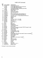
AIR COMPRESSOR
PARTS LIST
ACCESSORIES
DIAGRAM
......................................
.......................................................
....................................................
TROUBLESHOOTING
GUIDE
.......................................
HOW TO ORDER REPAIR PARTS
...................................
7
7
7
8
8
8
8
8
8
8
9
g
9
10
11
13
14
16
FULL ONE YEAR WARRANTY
AIR COMPRESSOR
if this air compressor fails due to a defect in material or workmanship within one year from the date of
purchase, return it to the nearest Sears store throughout the United States and Sears will repair it,
free of charge.
if this air compressor is used for commercial or rental purposes, the warranty will apply for thirty days
from date of purchase.
This warranty gives you specific legal rights and you may also have other rights which vary from state
to state.
Sears, Roebuck and Co., Sears Tower, Dept. 698/731A, Chicago, iL 60684
SAFETY
GUIDELINES
This manual contains information that is important for you to know and understand•
This information relates to YOUR SAFETY and PREVENTING
EQUIPMENT
PROBLEMS.
To help you recognize this information we use the following symbols. Please read the manual and
pay attention to those sections.
...... Nh_G
;;II-_ORTAa_T _,IFQRMATION
FOR PREVE'IT',NG ;t._JURY OR LCSS OF L_FE.
information
equipment.
for
preventing
damage
to
Note
Information that you should pay special attention to.
3
i
L
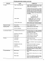
WARNIN'G
I¸
PLEASE READ THE FOLLOWING
CHART.
AREA
HAZARD
SAFEGUARDS
indicates where a hazard
can occur.
indicates what can happen if precautions are not observed.
indicates how to avoid the hazard and what
Moving Parts
Loose items, or parts of the body
may get caught and cause serious injury or damage.
special protective clothing, equipment,
precautions will be used.
Never operate the compressor
guard removed.
and
with the belt
Keep small children, your hands, and all
items away from the flywheel and belt.
Unit cycles automatically when
power is ON. During service or
repair activities, this automatic
cycling may cause a hazard.
Always unplug the unit before attempting repair or maintenance of the compressor. Also,
make sure the pressure is released from the
compressor and air tank.
Hot Parts
Air compressors
running. Serious
suit if touched,
get hot when
burns may re-
Never touch the compressor,
tubing, or
motor during or immediately after operation
of the compressor.
Air Tank
Air pressure or mechanical loads
that are higher than design loads
may cause the tank to rupture.
Do not adjust, remove, or defeat the safety
valve. Check the valve from time to time by
pulling the ring on the valve. If the valve is
stuck or does not operate smoothly, it must
be replaced.
Do not adjust, remove, or defeat the pressure switch.
Never use a motor with higher horsepower
rating than the one supplied.
The compressor was not designed to be
powered by a gasoline engine. Do not substitute a gas engine.
Electrical
Shock
Changes to the air tank structure
will cause the tank to weaken.
Tank rupture or explosion may
occur.
Never drill into, weld, or change the tank in
any way.
This unit is powered
240 volts.
Always unplug unit prior to doing any maintenance or repair,
by 120 or
Never use the unit outdoors when it is raining.
Always plug the cord into an electrical outlet
with the specified voltage and adequate fuse
protection.
4
AREA
HAZARD
SAFEGUARDS
Use of unsuitable solvents
The solvents l,l,l-Trichlorethane
and Methylene
Chloride
can
chemically react with aluminum
used in paint spray guns, paint
pumps, etc. and cause an explosion. These solvents can also
react with galvanized components and cause corrosion and
weakening of parts.
This hazard does not affect your compressor
outfit - but it may affect the equipment used
with the outfit. Read the label or data sheet
for the material you intend to spray. Equipment containing
aluminum or galvanized
parts that will come in contact with these solvents, and that can contain pressure, must
not be used with these solvents, You must
either change the material, or use only
stainless steel spray equipment.
Toxic Vapors
Compressed
may contain
monoxide.
Never directly inhale the compressed air produced by this unit.
air from this unit
poisonous carbon
Certain sprayed materials such
as paints, weed kitler, sand,
insecticides, etc., may be harmful
if used in a closed area or if
inhaled.
Compressed Air
Compressed air may propel dirt,
metal shavings, etc. and result in
possible injury.
SPECIFICATION
Model No.
HP
Displacement CFM
Bore
Stroke
Voltage-Single Phase
Minimum Branch Circuit Requirement
Fuse Type
Amperage at Max. Pressure
Air Tank Capacity
Approximate Cut-in Pressure
Approximate Cut-out Pressure
SCFM at 100 psig
SCFM at 90 psig
SCFM at 40 psig
919.174211
1
8.8
23/4"
2"
110-120
Be certain to read labels when spraying
paints or poisons.
Use a mask or respirator whenever there
chance that you might inhale anything
you are spraying. Read all instructions
that you know that your mask will protect
from what you are spraying.
is a
that
so
you
Never point any nozzle or sprayer toward a
person or any part of the body.
Always wear safety goggles or glasses when
spraying.
CHART
919.174310
1
8.8
23/4"
2"/_J"
110-220"
919.174410
1
8,8
919.174320
2
9.2
23/4"
23/4"
2"
110-120
2"
220-240
20 amp
20 amp
20 amp. min.
15 amp min.
"Fusetron" Type T "Fusetron ° Type T "Fusetron" Type T "Fusetron" Type T
18.2
18.2
18.2
9.9
12 gal.
12 gaL (ASME)
12 gal. (ASME)
20 gal. (ASME)
80 psig
80 psig
80 psig
80 psig
100 psig
100 psig
100 psig
100 psig
5.t
5.1
5.1
5.6
5.3
5.3
5.3
6.1
6.6
6.6
6.6
7.5
_ SCFM (Standard Cubic Feet per Minute): Unit of measure of air delivery.
SLM (Standard Liters per Minute): Metric unit of measure of air delivery.
PSIG (Pounds per Square Inch Gauge): Unit of measure of pressure.
kPa (Kilo Pascals): Metric unit of measure of pressure.
5
THiS
GENERAL
MANUAL iS DESIGNED TO MAKE iT AS EASY AS POSSIBLE
FOR YOU TO SET UP, OPERATE AND MAINTAIN
YOUR NEW AIR COMPRESSOR
ASSEMBLY
INFORMATION
You have purchased a complete portable compressor
outfit consisting of a 2 cylinder single-stage air
compressor with air tank, air hose assembly, wheels
and handle. You will also find an air chuck and a
helpful "Power Painting With Sprayers" booklet. The
2 horsepower unit has a removable foot extension
bracket which allows for stationary mounting.
These units can be used for operating caulking guns,
grease guns, air brushes, sandblasters, air tools, etc., or
inflating tires and plastic toys, spraying weed killer,
insecticides, etc.
GENERAL
DESCRIPTION
Tools Needed For Assembly
Tools needed are: (1) a 9/ld' socket or open end wrench
for attaching the wheels and hose adapter; and (2) an
adjustable wrench for attaching the pressure regulator,
and (3) a 7/16"open end wrench for attaching the air
pressure gauge, (4) a 7A6"socket or open end wrench for
attaching the foot extension bracket (2 hp. unit only), (5)
a 3/16"hex key for installing the plug in the regulator and
(6) pipe thread sealant.
Attaching Wheels, Handle, Etc.
i
OF OPERATION
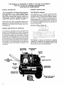
To compress air, the pistons move up and down in the
cylinder. On the downstroke, air is drawn in through the
air intake valve. The exhaust valve remains closed. On
the upstroke of the piston, air is compressed. The intake
valves close and compressed air is forced out through
the exhaust valve, through the check valve and into the
air tank. Working air is not available until the compressor
has raised the air tank pressure above that required at
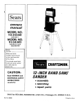
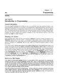
the air outlet. The air intake opening must be kept clear
of obstructions which could reduce air delivery of the
compressor.
AIR INTAKE
AND FILTER
INSTRUCTIONS
....
i
":""-'- V'HEELS
A;_D "b':[[CLE
9£ ;'DT
_F O_qDE [.DEQU;TE
.?.LZ,LR,:.;"CE _T,CE:LIT"" OR SU_'-'OR_" FOR :J_L!
£ "%_,E
U!;LF OR C.OV';,: ST;!RS /.[:: STZ=S.
TXE U;4ZT r._US- _E L;-TED ©': PL!_-:EE U_
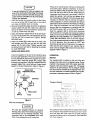
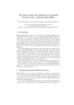
See diagram on page 10 for attaching air pressure
regulator (46), wheels (38), foot extension bracket (43)
and handle (47). Refer to the illustration, page 10, Key
No's. 22, 39, 40, 42, 44, 45, 84, 85 and 86.
ON-AUTO/OFF
SWITCH
SAFETY
VALVE
AIR
COMPRESSOR
PUMP
____
BUTTON
PLUG
RE
REGULATOR
0
PLUG
AIR
CONNECTION
DRAIN COCK VALVE
(NOT SHOWN)
6
It may be necessary to brace or support one
end of the outfit when attaching the wheels
and the foot extension bracket because the
outfit will have a tendency to tip over before
wheels are attached.
1. insert the handle into pockets under the tank base.
Put one set screw (22) through hole in one side of
tank base and tighten down on handle.
2. Remove the protective paper strip from the adhesive
backed rubber foot strip (45). Attach the rubber foot
strip to the bottom of the foot extension bracket (43)
or tank teg. Press firmly into place.
3. Attach foot extension bracket (43) to the air tank breck. et. Use one cap screw (44), one Iockwasher (87) and
one hex nut (42) at each end. Tighten. (Model
9!9.174320 only)
4. Attach one wheel (38) to each side of the outfit. Use
one shoulder bolt (39) and one hex nut with lock
washer (40) for each wheel. Tighten securely. Use
the bracket lower bolt hole for attaching the wheels
on model 919.174320.
Place unit on a level surface. Remove oit fill plug (50)
and slowly add a special compressor oil such as
Sears 30-16426 or SAE 20-20W SF motor oil until it is
even with the top of the oil fill hole. When filling the
crankcase, the oil flows into it very slowly. If the oil is
added too quickly, it wilt overflow and appear to be
full. (Crankcase oil capacity is 16 fluid ounces). Multiviscosity oil (10W 30) may be used but will result in
carbon deposits on critical components and reduce
performance and compressor life. Replace oil fill plug
(50). Plug the compressor into the correct power
source• Start the compressor by switching the ONAUTO/OFF switch (20) to the ON-AUTO position.
Open the regulator (46) by turning knob clockwise
fully to permit air to escape and prevent air pressure
buildup in the air tank. RUN THE COMPRESSOR 30
MINUTES IN THIS MANNER TO LUBRICATE PISTONS AND BEARINGS. Shut off air with regulator
(turn knob counterclockwise) and let the unit pump up
to cut-off pressure. Turn the switch to "OFF" and
check the oil level; add oil if necessary. Turn switch to
"ON" and the unit is ready for use. Connect the air
hose to the air adapter (86) located at the end of the
regulator. Refer to Figure 1.
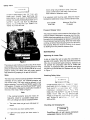
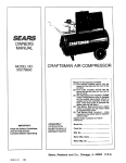
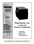
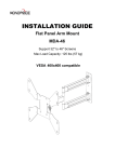
INSTALLING REGULATOR
install the regulator on the end of the manifold using
the short pipe nipple (84). The arrow must point away
from the manifold in order for the regulator to function
properly. Next, install the gauge (85), adapter (86)
and plug in the regulator. The plug is supplied with the
regulator. (Note: Use a small amount of pipe thread
sealant on all pipe thread joints.) Refer to Figure 2.
MANI-
REGULATED
PRESSURE GAUGE
FOLD
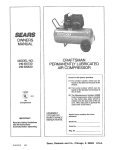
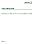
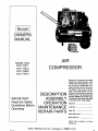
OPERATION
Manifold
The manifold (28) is located on the top of the unit
between the motor and air compressor pump. On the
manifold is the pressure switch (20), safety valve (29),
regulator (46) and pressure gauge (27). The gauge
shows the air tank pressure. The air pressure coming
from the air tank is controlled by the regulator knob. Turn
the knob clockwise to increase pressure and counterclockwise to decrease pressure. Refer to Figure 3.
ADAPTER
Pressure
Switch
REGULATOR
PIPE
NIPPLE
Figure 2
Start=Up Procedures
All units are shipped without oi!. Serious
damage may result if the following
break-in
instructions
are not closely followed. This
Operation has to be completed only once
when first putting the unit in service.
:'_gS;C_I.
"_=
7_C I iS ..........
:' &T:b!G AHC _
" +'-ATTE:,';F"-_
H-F-%T
TH........ qG,- AND
.......
- ..........
= ......
" - _
"
""
1_=-'f
............
' ....
-_=-_
......
......
=w--'"•:
_............
' .............
....
The pressure switch (20) starts the motor when the air
tank pressure drops below the factory set cut-in pressure and stops the motor when the air tank pressure
reaches the factory set cut-off pressure. (See specification chart, page 5.)
Safety Valve
OVER-Pk,
Note
ESSURiZATION
OF
THE
AIR
TANK
MAY CAUSE
TANK RUPTURE
OR
EXPLOSION.
THE OUTFIT
IS PROTECTED
FROM THE OVER-PRESSURIZATION
BY A
SAFETY
VALVE.
DO NOT
ELiMiNATE,
biAi{E
AC, JUSTbIENTS
OR SUBSTITUTIONS TO THIS DEVICE.
PRESSURE
TANK
PRESSURE GAUGE
Avoid using long extension
cords. They can
cause a power loss to the motor. Add extra air
hose instead of extension cords.
If an extension cord must be used, follow the recommendations listed below using a 3-wire extension cord.
Minimum Wire Size
12 gauge
Cord Length
0-50 Feet
Pressure
Release
Valve
The pressure release valve located on the bottom of th=
pressure switch is designed to unload air from the compressor head automatically at unit shut off. This protects
the motor from starting against air pressure remaining in
the compressor head and tubing. When the motor stops
running, air wilt be heard escaping from the valve for a
few seconds. When the motor is running, no air should
be leaking from the pressure release valve.
MAINTENANCE
Replacing Air Intake Filter
Figure 3
The pressure switch (20) is pre-set to shut off the motor
automatically at the maximum operating pressure. If the
pressure switch does not shut off the outfit at its cut-off
pressure setting, the safety valve will protect against
high pressure by popping at its pre-set pressure.
Motor
A dirty air intake filter will not allow the compressor tO
operate at futl capacity. When the intake filter becomes
dirty, oily, or covered with paint overspray, replace it. Do
not operate the compressor with the air intake filter
removed. To replace the filter, use needle nosed pliers
and pull or pry the old filter out. Replace with new. Refer
to Figure 1.
Checking
Safety Valve
The motor has a thermal overload protector. If the motor
overheats for any reason, the overload protector will
shut off the motor. The motor must be allowed to cool
before restarting. Turn the ON-AUTO!OFF switch to the
OFF position. To restart, turn the ON-AUTO/OFF switch
to the ON position. Depress the reset button located on
the end of the motor, Refer to Figure 1.
Note
If the overload protector shuts the motor off
frequently, check for a possible voltage problem. Low voltage can also be suspected when:
1. The motor does not get up to full power or
speed.
2.
Fuses
blow out when
starting
OVER-PRESSUR_ZAT[OI:
C_,USI;,JG TANK
RUPTURE OR EXPLOSION _',';A\' OCCUR IF
THE SAFETY VALVE _OES NCT WORK
PROPERLY,
OCCASIONALLY
PULL THE
RING ON THE SAFETY VALVE TO MAKE
SURE THAT THE VALVE
OPERATES
FREELY. IFTHEVALVEiS
STUCK 0_ DOES
NOT OPERATE SMOOTHLY. I- r,',U_-T EE
REPLACED.
Checking and Changing Oil
motor.
3, Lights dim and remain dim when motor is
started.
Overti_lirtg with oil will cause premature
compressor failure. Do not overfill.
Checkoil level in
the crankcase before each use. The oil
level should be even with the top of the fill hole and must
not be allowed to be lower than %" from the top at any
time. It is recommended that the oil in the base (51) be
changed after every 100 hours of operation. To drain the
oil, remove the oil drain plug (50) and collect the oil in &
suitable container. Be sure to replace the plug securely
before adding new oil. Use a special compressor oil,
such as Sears 30-16426 or SAE 20-20W SF motor oil
(crankcase oil capacity is 16 fluid ounces). Under
extreme winter conditions use 10 weight oil.
Replacing Belt
SERIOUS
INJURY
OR
DAMAGE
MAY
OCCUR tF PARTS OF THE BODY OR LOOSE
ITEMS GET CAUGHT
tN MOVING
PARTS.
NEVER OPERATE
THE OUTFIT
WITH THE
BELT
GUARD
REMOVED.
THE
BELT
GUARD
SHOULD
BE REMOVED
OHL"
WHEN
THE
POWER
CORD
iS
DISCONNECTED.
Location of Air Compressor
Locate the unit in a dry, clean, cool and well ventilated
area. The compressor crankcase and head are designed with fins which allow for proper cooling. Clean or
blow off fins and any other parts of the compressor that
collect dust or dirt. A clean compressor runs cooler and
provides longer service. Do not place rags, containers
or other material on or against the belt guard which
would obstruct ventilation openings necessary for
proper compressor operating temperature, tf humidity is
high, a Sears air filter and separate adapter can be
attached to the regulator (46) on the manifold to remove excess moisture.
Draining Water From Air Tank
The motor is mounted on an adjustable motor base. By
loosening the wing nut (25), the motor can be tilted in to
allow for easy tightening or removal of the belt (73).
To replace belt:
1. Unplug unit from power source before repairing.
2. Remove screws (1) from the back of the belt guard.
Remove belt guard (2).
3. Loosen wing nut (25) and tilt motor in.
4. Remove belt and replace with new.
Note
".....
" ,..
....,F _©T _h,4N,:=.
r, ......
T:4E WATE,-4 '_'
_'
,1=_
.....
....
"" " ....
..... : AI'JD
...... ' ":" : .J _'4l:,:
TAME
:s
: _ T_-E -, " "
,_ 'H .........
-=L :.W.
Water should be drained from the air tank periodically
depending on where and how often the outfit has been
used. If humidity is high, drain more often, To drain the
water that has gathered in the air tank, open drain cock
valve (41, page 10) and allow to drain. When empty,
close the valve tightly before operating the compressor.
Note
If drain cock valve is clogged, release air
pressure in the air tank and then remove.
Clean and reinstall the valve.
The belt should be centered over the grooves
on the flywheel and motor pulley.
.5. Push the motor back into regular position and tighten
wing nut securely by hand. Proper tension is approximately V4' belt deflection measured midway between the pulley and flywheel when a 3 pound weight
or equivalent finger pressure is applied at this point.
A loose belt will squeal at unit start-up.
6. Replace belt guard (2) and screws (1).
Air Compressor
1
73
74
75
25
48
8O
35
5O
47
PARTS
KEY
NO,
1
2
3
4
5
6
7
8
9
* 10
11
12
13
14
15
16
17
18
19
20
21
22
23
24
25
26
27
28
29
30
31
32
33
34
35
LIST
PART NUMBER
DESCRIPTION
SSF-953-ZN
CAC-22
CAC-142
SSF-6627
CAC-2
SSF-8113-ZN
265-18
LA-1575
SSF-935
30-16279
SS-8553
STD575025
STD575026
CAC-190
SSF-955
SSP-9401
STD575050
STD575051
CAC-137
CAC-437
Self tapping screw (7 used)
Belt guard
Belt guard closure
Stud
Bracket
Lock nut
Filter retainer
Label
Screw #8-32 x _" (2 used)
Kit of two intake filters (1 used)
Connector body
W' Nut (2 used)
V4"Ferrule (2 used)
Pressure release tube
Screw 3/s-16 x 11/2
" (5 used)
Connector body
1/2"Nut (2 used)
'/=" Ferrule (2 used)
Outlet tube
Check valve
SUDL-403-1
CAC-438
SUDL-404-1
CAC-462
SUDL-402-2
SS-391
PU-2859
C-PU-2833
STD580104
STD541631
MO-6026-p
MO-6223-P
C-5A-332
CAC-226
TIA-4125
TIA-4325
SS-2109
SSF-6086
SSF-958-ZN
SSW-8214
SUDL-59
SUDL-54
Cord assembly (Models 919.174211 & 919.174310)
Cord assembty (Model 919.174410)
Cord assembly (Model 919.174320)
Pressure switch
Cord assembly (motor to pressure switch)
Set screw (2 used)
Motor pulley (Models 919.174211, 919.174310 & 919.174410),
Motor pulley (Model 919.174320)
Key
Wing nut
Motor_.l_P (Models 919.174211, 919.174310 & 9
Motor 2-HP (Model 919.174320)
Gauge
Manifold
Safety valve (ASME) (Models 919.174310, 919.174320 & 919.174410)
Safety valve (Model 919.!74211 )
Nippte
Speed nut
Screw
Cord clamp
Hold down screw
Pin
"See page 13 for parts ordering information.
1!
PARTS
KEY
NO.
36
37
38
39
40
41
42
43
44
45
: 46
47
48
49
50
*
*
*
*
*
*
*
*
*
*
*
51
52
53
54
55
56
57
58
59
60
61
62
63
64
65
66
67
68
69
7O
71
72
73
74
75
PART NUMBER
TA-4036
TA-4038
TA-4040
LA-1654
LA-1682
CAC-492
CAC-60
STD541437
SS-2707
STD541025
CAC-105
STD522507
SUDL-6-1
30-16025
SUDL-43
SSF-925
SSF-928
SSP-1413
SSP-1413
265-3
265-16
265-41
265-4-1
SSF-927
265-410
CAC-207
265-15
265-191-1
265-192-1
265-195-1
265-145-2
265-196
265-29
SSF-9821
265-26-1
266-25
265-24-1
265-28-1
265-19
265-6
265-111
C-BT-215
STD523107
SSN-1014-ZN
DESCRIPTION
Air tank (Model 919.174211)
Air tank ASME (Models 919.174310 & 919.174410)
Air tank ASME (Model 919.174320)
Label (Models 919.174211,919.174310 & 919.!74410)
Label (Model 919.174320)
Wheel (2 used)
Shoulder bolt (2 used)
Hex nut with lock washer
Drain cock valve (V4")
Hex nut 1/,,"-20(2 used) (Model 919.174320 only)
Foot extension bracket (Model 919.174320 only)
Cap screw 1/4"-20× 3/4"(2 used) (Model 919.174320 only)
Rubber foot strip
Regulator
Handle
Cap screw V4"-20 × 7/8"(12 used)
Cap screw sA6"-18x 1V4" (4 used)
Oil fill plug (1/4")
Oil drain plug (1/4")
Base
Base gasket
Needle bearing
Crankcase and cylinder
Screw (4 used)
Connecting rod assembly (includes 2 SSF-927 screws) (2 used)
Piston pin plug (4 used)
Piston (2 used)
Oil ring (4 used)
Oil ring expander (2 used)
Compression ring (4 used)
Valve plate
Exhaust flapper valve with corner bevels (2 used on valve plate) I_
Restrictor plate (2 used)
Screw (8 used)
Head gasket
=r':-**Intake flapper valve (2 used on head) K
Head
Valve plate gasket
Piston pin (2 used)
Vent filter
Oil seal
Poly-V-belt
Cap screw sA6"- 18 × 3/4"
Belleville washer
* See page !3 for parts ordering information.
12
LiST (Continued)
PARTS
LiST (Continued)
KEY
NO.
KEY
NO.
PART NUMBER
DESCRIPTION
76
77
78
* 79
80
81
82
265-2
265-9
265-23
265-13
265-1
SS-3222-CD
SSW-7367
Flywheel
End plate
Needle bearing
End plate gasket
Crankshaft
Pipe plug 1/4"
Strain relief (2 used)
PART NO,
DESCRIPTION
86
87
LA-1704
LA-1659
LA-1700
LA-1660
SS-2071
C-GA-329-P
H-2099
21181-506
88
89
LA-1580-1
LA-1701
Label (Model 919.174211)
Label (Model 919.174310)
Label (Model 919.174410)
Label (Model 919.174320)
Nipple 1/4"x 1 V2"
Gauge
Adapter
Lockwasher (2 used)
(Model 919.174320)
Label (Model 919.174410)
Label (Model 919.t74410)
Label (Model 919.174410)
83
84
NOT ILLUSTRATED
SSH-8
:30-16162
630-01
SI-30-14-2
Air chuck
Air hose assembly (1/4"x 15')
"Power Painting With Sprayers" Booklet
Owner's Manual
* Parts Ordering Information
Key No. 10, 52, 66, 69, 71, 72, 79 available as individual parts and part of kit KK-4268.
Key No. 59, 60, 61 only available as part of ring kit KK-4209.
Key No. 63, 65, 67 only available as part of valve kit KK-4275.
ACCESSORIES
CURRENT
1.
2.
3.
4.
5.
6.
7.
FOR USE WITH SEARS COMPRESSORS
AVAILABLE
THROUGH
GENERAL SALES CATALOG OR AT FULL LINE SEARS STORES.
Spray Guns
Sandblasters
Paint Tanks
Blow Guns
Air Brushes
Air Tanks
Air Tools: sanders, drills, impact wrenches,
hammers
8. Air Hose: 1/4",s/is" or 3/8" inside diameter, 15', 25',
50' !engths
9.
10.
11.
12.
inflator Kits
Quick Connector
Viscosimeter
Air Line Filters
Sets: various sizes
13. Oil Fog Lubricators
14. Tire Air Chucks
15. Air Caulking
16. Air Powered
Gun
Washer Gun
THE
TROUBLESHOOTING
CAUSE
PROBLEM
Motor Will Not Run
Excessive tank pressure
(safety valve pops off),
14
GUIDE
CORRECTION
Motor overload protection switch
has tripped
Let motor cool off and reset switch by pressing the red reset button located on the end
of motor.
Tank pressure exceeds
switch cut-in pressure.
Motor will start automatically
when tank
pressure drops below cut-in pressure of pressure switch.
pressure
Fuse blown, cimuit breaker tripped.
Check fuse box for blown fuse and replace as
necessary. Reset circuit breaker. Do not use
a fuse or circuit breaker with higher rating
than that specified for your particular branch
circuit (see specification chart, page 5,)
Wrong gauge wire in extension
cord,
Check for proper gauge wire. Refer to wire
size recommendations under Motor Section
of this manual.
Pressure release valve on pressure switch has not unloaded
head pressure.
Bleed line by pushing lever on pressure
switch to OFF position which opens the pressure release valve. If valve still does not
open, replace it.
Check valve stuck.
A defective check valve results in a constant
air leak at the pressure
release valve
attached to the side of the pressure switch
(20) when there is pressure in the air tank
and the compressor is not running. Remove
and clean or replace check valve (do not
overtighten).
Loose electrical connections.
Check in motor connection box and pressure
switch. Pressure switch cover can easily be
removed by lifting cover at rear of switch.
Capacitor on the motor.
Return to Sears Service Center to check and
replace if necessary.
Faulty motor.
Unless motor is visibly damaged, remove
motor and have it checked at a local Sears
Service Center.
Pressure switch does not shut off
motor.
Move pressure switch lever to the "off" position. If outfit still does not shut off, unplug it.
Remove pressure switch release valve. Plug
outfit back in. If it still runs, replace pressure
switch, ff it doesn't run, replace pressure
release valve.
Pressure switch cut-out too high.
Return outfit to Sears Service Center to
check and adjust or replace if necessary.
TROUBLESHOOTING
PROBLEM
Air Leaks
GUIDE
(Continued)
CAUSE
CORRECTION
Tube or hose fittings loose.
Tighten fittings with audible leak and check
fittings under pressure with soapy water
solution. (Do not overtighten).
Defective check valve.
A defective check valve results in a constant
air leak at the pressure
release valve
attached to the side of the pressure switch
(20) when there is pressure in the air tank
and the compressor is not running. Remove
and clean or replace check valve (do not
overtighten).
Leak at welds.
DO NOT DR_LL INTO, WSLD OR
OTHERWISE MODIFY AIR TANK
OR TANK WiLL BE WEAKENED.
TANK MUST BE REPLACED.
Air leak in safety valve.
Operate safety valve manually by pulling on
ring. If valve still leaks, it should be replaced.
Restricted Air Intake
Dirty air filter.
Clean or replace with new.
Squealing Sound
Belts too loose.
Tighten wing nut on motor mount.
No oil in compressor.
Add oil to top of fill hole in base.
Prolonged excessive use of air.
Decrease amount of air usage, compressor
is not large enough for air requirement. See
specification chart, page 5.
Restricted air intake filter.
Clean or replace air intake filter.
Belt too loose.
Tighten wing nut on motor mount.
Hole in hose.
Check and replace if required.
Loose pulley.
Tighten pulley set screw.
Low oil level.
Check oil level and maintain at prescribed
level.
Flywheel loose.
Make sure flywheel
screw.
Compressor bolts loose.
Check all bolts and tighten as required.
Loose belt.
Adjust wing nut on motor mount.
Carbon build up.
Remove head and valve plate. Clean top of
piston and bottom of valve plate. Reassemble using new gasket and torque screws to
25-30 Ft.-Lbs.
Belt too loose.
Adjust tension
mount.
using
wing nut on motor
Belt too tight.
Adjust tension
mount.
using
wing
Pulley wobble.
Check for worn keyway or pulley bore resulting from running the compressor with loose
pulleys. Also check bent motor shaft.
Low Discharge Pressure
Knocking
Excessive Belt Wear
is tight by tightening
nut on motor
15
Sears
OWNERS
MANUAL
AIR
COMPRESSOR
SERVICE
MODEL NOS.
919.174211
919.174310
919.174320
919.174410
Now that you have purchased your Sears Air Compressor, should a
need ever exist for repair parts or service, simply contact any Sears
Service Center and most Sears, Roebuck and Co. stores. Be sure
to provide all pertinent facts when you call or visit.
The model number of your Sears Air Compressor is 919 ____
This number can be found on the label which is located on the front
of the tank saddle.
HOW TO ORDER
REPAIR PARTS
WHEN ORDERING REPAIR PARTS, ALWAYS GIVE THE FOLLOWING INFORMATION:
• PART NUMBER
• MODEL NUMBER
• PART DESCRIPTION
® NAME OF ITEM
NOTE:
If service or repair parts are required for the motor, supply all motor
nameplate information including manufacturers.
All parts listed may be ordered from any Sears Service Center and
most Sears stores.
If the parts you need are not stocked locally, your order will be
electronically transmitted to a Sears Repair Parts Distribution Center for handling.
Sears,
SI-30-!4-2
Roebuck
and
Co., Chicago,
BL 60684
U.S.A.
PRINTED
IN US A