1
!iiiiii!ii_ili_:
_!
MODEL NO
661.623920
661.624420
661.624530
661.624630
661.624670
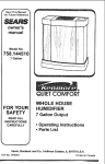
Kenmore
CONV
TIBLE
DOWNIFRONT
OUTLET
EVAPORATIVE AmR COOLER
AND
o Installation
o Operation
e Repair Parts
SEARS.
30780-6
ROEBUCK
AND
CO.,
Chicago.
1L
60684
U.S.A.
CONTENTS
INSTALLATION
Tools
and
Supplies
You Need ................
3
Safety Rules
............
Data ...................................
Locating
Your
Converting
to Side
Mounting
Electrical
Final
3
3
......................
Outlet
...................
Check
5
and Adjustment
6
7
..........
8
List .........................
9
NEED ADVICE? MISSING
...................
10
Spring, Summer and Fall Care ...............
Taking Off and Putting On Grills ...............
Taking Off Pad
...............
Cleaning ..........................
Putting on Pad .................
Oiling ................
Blower Bett Adjustment
.......................
REPAIR PARTS .......................
4
Cooler-,
............
Connections
..........................
Assembly
Startup
Cooler
COOLER
USE
Cooling Your Home
Cooler
Care
PARTS? * CALL MANUFACTURER
Just dial this toil free number' 1-800-643-2742
11
11
12
12
t3
13
13
14
FIRST:
to get facts fast:
Call Monday through Friday 8:00 A.M. to 5:00 P,M. - Central Time
Our experienced
Hotline Service Representative can:
=
Answer installation questions.
=
Provide prompt shipment of missing parts.
YOUR SATISFACTION
IS OUR NUMBER ONE PRIORITY
Reminder: The person you will be talking to is Not a SEARS store employee
and cannot handle exchanges, arrange service calls etc._ This must be handled
through you r Sears Store or Catalog Order Depar'tmer_t Th{s toll-free n umber
is for technical assistance only.
FULL ONE YEAR WARRANTY
ON SEARS EVAPORATIVE
COOLER
One year from the date of purchase when this Kenmore
Roto-Bett evaporative air cooler is installed and
maintained according
to our instructions
Sears will repair defects in material or workmanship free of charge
FIVE YEAR LIMITED
All
Sears Kenmore
Roto-Belt
cooler
cabinets
and blower
WARRANTY
housings
are warranted
against
rusting
out
becoming inoperative after one year and through five (5) yeats from the date of purchase Sears Roto-Belt
water reservoirs and louvers are warranted also against leaking and deterioration
due to water corrosion
same period
of time
WARRANTY
SERVICE
THROUGHOUT
This warranty
You pay for labor
IS AVAILABLE
THE UNITED
gives you specific
SEARS, ROEBUCK
BY SIMPLY
Note: Replacement
CONTACTING
THE NEAREST
legal rights, and you may also have other rights which
AND CO., DEPT. 698/731A, SEARS TOWER,
i i ill
of filter pads is normal
INSTALLATION
All installation labor arranged
formed in a ne_' workmanship
SEARS SERVICE
CENTER
STATES
...................
SEARS
and
cooler
for the
maintenance
vary from state to state
CHICAGO,
IL.. 60684
i iiii, ,,ll,,i
and is not covered
in the warranty
POLICY
by Sears shall be permanner in accordance
with generally
accedpted
trade practices, Further, all
ir'_staltations shall comply with all local laws, codes,
regulations and ordinances
The customer shalt also be
protected, during installation, by insurance relating to
property damage, Workmen's Compensation
and Public Liability
SEARS
INSTALLATION
WARRANTY
In addition to arty warranty extended to you on the
Sears merchandise
involved which warranty becomes
effective the date the merchandise
is installed, should
the workmanship of any Sears arranged installation
prove faulty within one year, Sears w{lf, upon notice
from you, cause such faults to be corrected at no atti=
tional cost to you
BNSTALLATgON
TOOLS
NEED
AND
SUPPLIES
YOU
WiLL
e Duct, As Required (a local sheetmetal shopcan
supply ducting)
o Equipment Suitable for Installing Duct Through
House Wal! or Roof
o Water Connection,
Use Kit # 62527, #62528 or
#62522 Saddle Valve See page 8 (Connect
Water line) for further information explaining
the different water hook ups
o Roof Stand Kit (if cooler is roof mounted)
Cooler 66t ,623920 use 32-6256 kit
Cooler 661 624420 use 32-6256 kit
Cooler 661 624530 use 32-6257 kit
o Cooler 661 624630 use 32-6258 kit
• Cooler 66to624670 use 32-6258 kit
• Pliers
o Screwdrivers
o
o
e
e
o
o
Adjustable Wrenches
Tubing Cutter
5/32 Hex Key Wrench
Electric Drill
Drill Bits
Hammer
o Duct Caulking
e 10 Sheet Metal Screws
o Wiring Supplies, as Required
Electrical Code
e Level
by Local
'
o 32-6251 (5 position) Wall Switch for Either New
or Existing Pump Type Cooler Wiring.
RULES FOR YOUR SAFETY
5, Never install or service a cooler during a stor m
or high wind conditions,You
could be injured o;r
lose or damage parts
1°
TO AVOID FIRE, SHOCK, AND SERIOUS
i
PERSONAL INJURY FOLLOW
WARNINGTHESE INSTRUCTIONS
6_ Never wear shoes with slick soles when you
work on a roof You may slip when you least
expect it
2. The installation
must conform to local codes
and utility standards,, Use the National Electric
Code if a local code does not exisL
7. Never drain water onto a roof Water residue
may cause you to slip or may stain your roof
Use a drain hose to run the drain water to a rain
gutter or to a drain,
3, Disconnect the electric power EVERY TIME you
work on your cooler When your hands are
inside the cooler you risk injury if the cooler is
accidently turned on from inside the home
4. If you mount the cooler on your
remember these safety tips:
8. To avoid injury never use the cooler without
connecting it to a house duct system or without
a sturdy mesh guard over the outlet,
home roof
DATA
Cabinet Dimensions
(inches)
Height
Width
Depth
Model
No,
Air Output Opening
(inches)
Height
Width
Operating
LbB_Weight
(with water)
--
661 623920
661 624420
661 624530
661624630
661 624670
29¾
29¾
33¾
36¾
36¾
29¾
29¾
33¾
36¾
363/,
35_
35_
37½
42_/'_
42_1 _
173/,
17¾
t9¾
I93/,
t9_
17_
17¾
t9¾
19=,_
19¾
WIDTH
195
190
235
285
289
-.-_>
SIDE
OUTLET
OUTPUT
(Cubic
RATINGS
Feet Per minute)
SEARS EVAPORATIVE
Model
No,
Industry
Rating
Model
No.
661
661
661
661
661
4500cf_
4000crm
5200clm
6600cfm
7200cfm
661
661
661
661
661
623920
624420
624530
624630
624670
623920
624420
624520
624620
624670
PAD USAGE
Sears
Pad Number
32-6293
32-6293
32-6294
32-6295
32-6295
BOTTOM
OUTLET
INSTALLATHON
LOCATING
YOUR
COOLER
Your cooler has been shipped ready for installation in a down discharge position. It can easily
be changed to side discharge, The cooler must
be securely fastened to a frame or pad mounL A
roof kit is available from Sears°
A duct must be attached to the cooler outlet° The
duct must be the same size as the cooler outlet°
Sudden duct size changes will decrease the output of your cooler,
The cooler installation must comply with local
codes, If you are not fully qualified to install a
cooler, get professional help.
Figure 1 shows locations for your cooler. Be
sure the intake louvers are clear of obstructions
and are accessable for removal. Do not locate
the cooler near vent pipes, chimneys, or exhaust
where odors or fumes may be drawn into the
house.The two drain holes on the cooler bottom
must be clear to allow overflow or drain access.
I::l::l
PH
m
l
m
ROOF KIT MOUNT
SIDE DISCHARGE
INTO HALL
SiDE
CONNECT
WIRIHG
DOWN DISCHARGE
CONNECT
TO HOUSE DUCTING
DISCHARGE
TO
HOUSE
BOX (FIGURE
ROOF KIT MOUNT
DOWN DISCHARGE
INTO HALL
DUCTING
2)
The wiring box is inside the cooler cabinet. The
electrical supply must be connected to the
cooler power leads inside the box after the
cooler in installed. The wiring box is factory
installed for coolers used in the down air outlet
position.
AIR DISCHARGE POSITION THEWIRING
BOX
IF YOU INSTALL THE COOLER IN THE SIDE
MUST BE MOVED. SEE PAGE 5.
i s.uT0FFPOWER
A'rTHE'ELE€ ICA= =7
SERVICE
BOX
BEFORE
STARTING
aNSTALLATnON
YOU MAY WANT
TO CONVERT
YOUR
COOLER
TO SIDE
DISCHARGE
(Figure
3)
H.n
CONVERTING
DISCHARGE
COOLER
(F|G.4)
TO SiDE AIR
SIDE OUTLET
,_
DOWN OUTLET
O Remove both louvers and set them where they
will not fall See pg_ 11, "Taking Off Louver"
Q Remove four
motor
grille clips on side opposite
(_ Remove a reservoir by pushing the water crossover tube from the grommet and lifting out the
reservoir,,
(_) Remove the second reservoir as above.
(_
Q Remove the screw that holds the wiring box,
O Remove 1,_inch diameter and _ inch diameter
knockouts,,
O Remove two plastic plugs..
® Loosen screw
bracket, slide
cabinet flange,.
9 Turn cooler to
holding pad motor receptacle
bracket up and detach from
Repeat on other side,.
side outlet position (Figure 5)
REASSEMBLY
AS SIDE
OUTLET COOLER (Fig 5)
(_) Move wiring box to new location,,
O Secure wiring box with screw removed
disassembly,
(_) Install
four
louver
clips
removed
disassembly,,
(_) Install two receptacle brackets removed
disassembly°
at
(_ Install
two
plastic
plugs
removed
disassembly
6. Assembly reservoirs, crossover tube and
ers after the cooler is installed in location,
soap or detergent to lubricate crossover
before inserting into grommet, DO NOT
OIL.
at
ROUTE WIRES INSIDE OF PANEL
at
at
®
louvUse
tube
USE
®
INSTALLATRON
LIFTING
COOLER
Lift at cabtnet corners
CAUTION: DO NOT LIFT ON THE LOUVERS,
REMOVE THE LOUVERS BEFORE LIFTING,
DO NOT LIFT ON THE CENTER OF THE
CABINET FLANGES
MOUNTING
COOLER
The cooler may be Ilfted by
putting a bar or strap through
the panel hole and lifting by
means of the beror strap (Fig
6)
(Fig. 7)
1o Prepare duct to fit model used,, See outtet size
specifications on page 3.
2. Cut opening in roof or wall to fit duct opening on
cooler and box in opening=
3. Install duct and secure to boxed-in opening
frame= Allow the two inches to fit into cooler
outlet. Allow duct length for cooler bottom to be
4 inches above roof at closet poiqL
4 Install flashing
entry,,
on roof or' wall to prevent water
I
NOTE: THE
BOTTOM
NEAREST
OUTLET
MUST
FACE EDGE
UP THE
ROOF. THE AIR
6,, Mount cooler on stand or pad Cooler must be
level front to back and left to righL Sears roof
stand kits are available..
7o Be su re to securely fasten four corners of cooler
to stand or pad.
8. Caulk duct to the cooler, Caulk the flashing°
5 Measure cooler and lay out mount location.
FLASHING
_/4
MAXIMUM
HEIGHT FOR
STAND SIDE EDGE TO
ALLOW RESERVOIR
CLEARANCE
8OXED
OPENING
RtS
ROOF STAND
(PURCHASE
KIT
SEPARATELY)
FLASHING
)UCT
4 INCHES
MINIMUM
L
SPACER
ABOUT
2 iNCHES
- FLASHING
PAD
1"THICK
RISER DUCT
INSTALLATION
ELECTRICAL
CONNECTIONS
Use only a Sears 32-6251 wall mounted switch..
This new cooler does not require prewetting the
pads before starting cooling and does not have a
pump Existing switches with "pump only" positlon are not usable.
The wiring must comply with local code& If you
are not familiar with the codes or wiring practices, get professional help.
NEW INSTALLATIONS
COOLER CHANGEOUT
Use Sears 32,6251 Switch
OR
INSTALLATIONS
CAUTION:
which is suitable for
BEGINNING
SHUT
POWER
either new installations or existing installations_
When installing a cooler or existing installation;
five wires must go to the cooler including
grounding connector. There are two cool positions and two vent positions. Figure 9 shows
how to wire the 326251 switch.
WARNING:
To
AT
OFF
THE
THE
FUSE
THE
WIRING
REDucE
THE
RIBBED
BEFORE
RISK
OF
FIRE
0R_
ELECTRIC SHOCK, DO NOT USE THIS FAN WITH ANY_
SOLID-STATE
SPEED CONTROL DEVICE
U
-----.-._-_r:ACTO
BROWN
ELECTRIC
BOX
FURNISHED
.............
RY WIRING
F{ELD
WIRING
PAD_
MOTOR
2
SPEED
BLOWER
4 STtl
MOTOR
[ PS
i
p._EN 1=0
_Tc_
_WHITE
VoR
AC
WALL BOX (SWITCH)
PAD
MOTOR
ROWN
L ....
RIRB£D
COOLER
FLOAT
VALVE
INSTALLATION
JUNCTION
BOX
INSTRUCTIONS
INSTALLATION
It is el tile
Splash
Utmost
Guard
Importance
Cover
that
be installed
the
Ftoal
exactly
VaIve
Splash
as described
Guard
_n lbe
OF OUTSIDE
ROLLERS
and
iIluslration
below
1) T he Float
Valve-Must
Ihe ver_ica_
_r_d cause
2) The
water
poSiI_on
the reservoir
Spoilt
waterfrom
in the
be mslalled
and
spurtirr£
Splash
Guard
with
tf nO! instaIled
draie
Water
pipes
Spout
Ihe
narrow
th_s way
the
FF{OM SPLASHING
'LeA,
VALVE
Cover
as illustrated
"_
el the float
in
float
witl hang
up
NOTICE
to overflow
ate
provided
arrdsptashingouts_deofthereservo_rs
Covet
side
below
TO INSTALLERS
to wevenl
Snap
l c, e5_
ZS_
(,_..
\
_'ARr
£ BAGI
iNSTALLATiON
FINAL ASSEMBLY
AND ADJUSTMENT
COMPRESSION
NUT
PUT FLOAT VALVE IN COOLER
Put the float valve through the spout hole and
cabinet hole Tighten the ring nut Be sure the float
moves straight up and down. TURN THE FLOAT
UNTIL A NARROW SIDE IS UP. Snap the Sp(ash
Guard Cover into the Water Spout as shown The
Water Spout and Splash Guard Cover are provided
to prevent water from "spurting "and splashing outside the Water Reservoir,
CONNECT
WATER
LiNE
FLOAT
VALVE
For outdoor Hook Up, use #62527 Copper Hook Up
Kit or #62528 Plastic Hook Up Kit Both kits contain
all necessary fittings to connect water to cooler For
indoor kit use copper tubing and #62522 self piercing saddle valve.
NUT
P R EpSuS!ON _
%
PUT IN OVERFLOW
PIPE (Fig. 11)
1 Push the drain fitting through the washer and
water tray hole Tighten the ring nut. Screw the
overflow pipe into the drain fitting Repeat for
the second tray.
FERRULE
ADAPTER
OVERFLOW
PIPE
NOTE:
INSTALL
DRAIN
FITTING
INVERTED tF COOLER IS MOUNTED ON A
PAD. CUT OFF THE OVERFLOW PIPETOP
FLUSH WITH THE HEXAGONAL RING.
DRAIN
WASHER
WATER LEVEL
MARK
Put in the float valve side tray first The crossover tube and grommet MUST be on the float
valve side (Fig 12).
Push the crossover tube into the grommet° Use
soap or detergent as a lubricant DO NOT USE
OIL,,
4 Put the second water tray in place. Push the
crossover tube into the grommeL
ADJUST
WATER LEVEL
5_ Turn on the water. Check the water level when
the valve shuts off, If the water' level is above the
tray water leve) mark bend the float rod down If
the level is too low, bend the rod up,,
GROMMET
I
GROMMETS
AND ALL CONNECTIONS
NOTE:
CHECK THE CROSSOVER PIPE
FOR LEAKS.
PUT LOUVERS
Seepage
FITTING
CROSSOVER
PiPE
ON COOLER
11
8
FLOAT
VALVE
IINSTALLATION
MOTOR
PULLEY
ADJUSTMENT
(Figure
13)
NOTE: ALL DUCT CONNECTED
COOLERS
MUST BE ADJUSTED
Long or small air ducts have excessive air
resistance
which decreases air output and
motor amperage, You may compensate for this
by adjusting the motor pulley. Use-a clamptype
ammeter to check the motor amperage
1o Check amperage
box,,
PITCH
ADJUSTMENT
SCREW
at the white lead in the wiring
2 If the amperage is less than the motor nameplate
amperage, loosen the pulley pitch adjustment
screw, turn the pulley _ turn clockwise, tighten
the screw and recheck the amperes Repeat as
necessary to bring the amperage to the nameplate rating°
3.
4
If the amperage
is too high, turn the pulley
ter - clockwise
as required.
Adjust
13).
the belt
tension
coun-
NOTE:
as required
(See page
INSPECTION
Before starting the cooler, make sure al! installations
and adjustments are correct. Be sure that:
e Cabinet
is level and duct is sealed
is securely
fastened
to the mount
o Cooler is grounded
Electrical connections
secure
o Blower wheel does not rub against housing.
o Water supply
is turned
STARTUP
are
on
...............................
OPERATION
CHECK
LIST
WITH SEARS SWITCH
(Five
Position)
Blower
Motor
32-6251
Pad
Motor_
Off
Off
Off
Low Veftt
High Vent
Low
High
Off
Off
Low Cool
Low
High
On
On
High Cool
amperage with theammeter;
all louvers must be tn place in the cooler;
setting
of
the drive
• Water line is connected securely and fittings
crossover tube grommets do not leak
e Float is adjusted
for proper water level
o Pulley alignment
page 13)
is OK
Belt tension
o Pads are correctly
installed
= Blower and both
receptacles
pad motors
o All louver clips are snapped
. ,,,,,_,_,,
To check out the installation follow this startup
procedure Set the control to each position and check
operation per the following chart, Be sure to open
windows or vents_,
Switch
When checking
otherwise
incorrect
pulley will occur
STARTUP
Cooler
IMPORTANT
and
is OK (See
(See page 13)
are plugged
tight
into
HOW TO USE YOUR
HOW
YOUR
COOLER
COOLER
WORKS
Your cooler evaporates water to cool air.
Evaporative air cooling is the same natural
cooling that happens when a breezesprings up
after a summer shower, You feel cool because
the rain water evaporates and carries away
heat
Your new cooler has a motor' (1) driven blower
(2) which draws outside air through pads (3)
which are turned by drive motors (4) The pads
turn through water in trays (5) filled by the
water float valve (6) and water crossover pipe
(7) Air passes through the pads, is cooled by
water evaporation, and is sent into your' home.
(Figure 14)
You may also run the cooler in "Vent"
you want fresh air and no cooling
when
Relative humidity affects the cooling capacity
of any cooler. See chart to determine the
maximum amount of cooling possible at your
outside temperature
and outside humidity
(Figure 15)
OUTSIDE
COOLING YOUR HOME
Your cooler and window or vents are the two
parts of your air cooling system Outside air is
filtered and cooled, goes through your home,
and carries away heat and household odors.
You control the air cooling flow to your rooms
by opening doors, windows, or vents.. (Figure
RELATIVE
HUMIOITY
- %
5
tO
15
50
30
56 o
58°
60 °
61 °
64"
90"
52_
64=
66 _
68 _
iOO"
58 =
71_
73_
74o
27_
79o
83°
40
50
60
67 °
69 °
72"
75°
75°
2B"
814
75°
79°
83_
87 _
g0 o
80 °
B_°
67 o
92=
g5 °
-
86_
8g °
95 _
iO0 _
o.
==
_O
t_O_
o
LOWEST
POSSIBLE
OUTPUT
TEMPERATURE
16)
You must have window, door, or vent openings
to let air out when the cooler runs. The total
opening areas you need are shown below:
MODEL
............
TOTAL
OPENING
AREA
661.623920
11 Square feet minimum
661 _624420
10 Square feet''rnin_mum
661.624530
12 Square feet minimum
661,624630
14 Square feet minimum
661.624670
16 Square feet minimum
TYPICAL
10
AIR FLOW
_.
CARE OF YOUR
CAUTION:
SPRING
SUMMER
ALWAYS UNPLUG YOUR COOLER BEFORE YOU WORK
ON IT YOU COULD BE HURT IFTHE COOLER IS TURNED
ON WHEN YOUR HANDS ARE tNS_DE THE COOLER
CARE:
CARE:
FALL CARE:
TAKING
COOLER
Clean your cooler (See page 12)
Oil your cooler (See page 13)
Put a new pad in if the old pad is plugged with dirt or water hardness, (See pages 12 and 13).
Check belt tightness
(See page 13)
Drain and clean the cooler every two months if your water is hard or the air is dusty
You may prolong pad life in many hard water areas if you drain the water tray every two to
three weeks (See page 12, Preventing mineral build-up),
Drain
Clean
Cover
Sears
the
the
the
has
OFF LOUVER
cooler and water line to prevent freezing
cooler, (See page 12),
cooler
covers to fit your cooler
(FIGURE
17)
PUTTING
damage
(See page I2)
ON LOUVER
(Figure
1 Unsnap the six louver clips
Use a small screwdriver
1 Put the louver bottom into water tray
2
2
Plug in the pad motor
3
Close the louver
Snap the six clips onto the louver
Tilt out the louver at the top
Unplug the pad motor plug
3 Take off the louver
Set it where it will not fall
INSERT
18)
SMALL
SCREWDRWER
)ER CLIP, PRY OPEN
PAD MOTOR
tl
PLUG
CARE OF YOUR
COOLER
TAKING
OFF PAD (Fig. 19)
1. Lift up the small roller ends to unsnap the two
center rollers Pull out the two small rollers
2. Pull out and turn the top roller bearing arm to
line up the slot
3+ Lift edge of pad from under the guide and pull
out the top roll end,
4, Take out the pad and bottom roller which will
slide out of the bottom slots.
CLEANING
YOUR COOLER
HELPS PREVENT
MINERAL
(FIG. 20)
BUILD-UP
'WITH A GARDEN HOSE. WATER
I_MAY HARM NEVER
THE MOTORS
OR GET
INTO 1
WASH YOUR
COOLER
[YOUR HOUSE,
DISCONNECT
THE
THE FUSE BOX,
ELECTRIC
POWER AT
J
2, Remove the Louvers., (See page 11 )
%
f
t
-"
t+
KIT
I
I
i WATER
, TRAY
...."_
"_.
NEVER DRAIN WATER ONTO A ROOF.
WATER RESIDUE MAY CAUSE YOU TO SLIP
OR MAY STAIN YOUR ROOF, USE A DRAIN
HOSE TO RUN WATER TO A RAIN GUTTER
I
I
1
I
OR TO A DRAINL
!
!
k,
,%
6. Take off the pads if they are dirty or clogged
Use a sponge and mild detergent to wash the
dirt or scale from the trays and grilles. DO
NOT
GET
WATER
ON
THE
PAD
MOTORS.
=
If the pads are clogged with hard water
deposits and dirt, replace the pads, See page
13
u
Put the overflow pipes and grilles in place
page 11 )
.,.i
I
5+ Drain the other tray
,
'_.,
f
3, Connect a garden hose to a water tray drain
fitting,, Unscrew and remove the overflow pipe
to drain the tray
4 Automatic
cycling.
BLEED--OFF
available (Sears 32-62562)
.,.
j
(See
12
/
I/
I
OVERFLOW
PIPE
CARE
OF YOUR
PUTTING
COOLER
ON NEW PAD
(Fig. 21)
SEARS
REPLACEMENT
MODEL
NUMBERSEARS
_
661.623920
661.624420
661.624530
661.624630
THE PADS NEED NO PREWETTING
__. Put the lower roller in pad.
Fit the lower roller into the botton slots in the
frame
..... ._61.624670
PADS
PAD NUMBER
42-6293
42-6293
42-6295
42-6295
Push the top roller through the pad, Fit the roll
end over the pad motor shaft drive block
_. Push the top roller end into the bearing
Q Turn the bearing arm to hold the rolter_
TUCK THE PAD EDGES
GUIDES ON EACH SIDE
O
UNDER
THE
2
Put the two small center rollers in place. Snap
the ends into the holders. (See lubrication
instructions below)
OILING
(Fig.22)
Use SAE 20 Non-detergent
per year.
motor
1
Fill the two blower
cups
2
Pot two or three drops in the two oil fiJl tubes on the
shaft bearing
oil once
(_
OIL
biower motor
(_)(Motors
have ]ifetime lubric, ation)
3
without
oil
fill
tubes
Put two or three drops in the end bearing on each pad
motor
BLOWER
(_
BELT
ADJUSTMENT
(Fig. 23)
©
OiL HERE ON
BY CHANGING
THE DIAMETER OF THE
MOTOR PULLEY. ADJUST BELT TENSION
l CAUTION: DO NOT ADJUST BELT TENSION t
ONLY BY MOVING THE MOTOR BRACKET.
EACH
1 If you can easily move the belt over 1 inch. it
needs adjustment.
2 To adjust belt tension, loosen the three motor
mount bolts,
3 Push the motor to tighten the belt until belt
moves about 1/2inch with finger force
4 Tighten the three motor mount bolts
13
LOUVRE
REPAUR PARTS
KENMORE
MODEL.
CONVERTIBLE
DOWN/FRONT
NOS. 661.623920,
OUTLET
661.624420,
47
'
EVAPORATIVE
661.624530,
AIR COOLER.
661.624630,
661.624670
1
1::
19
10
25
(
23
4O
17
38
23
3O
35
34
25
28
48
50
49
_
56
/
55
60_
53
\
\
56
55
54
14
26
REPAaR PARTS
KENMORE
CONVERTIBLE
MODEL
NOS. 661.623920,
NOTICE:
Order by PART NUMBER,
KEY
NO
PART
DOWN/FRONT
661.624420
not by Key Number
NUMBERS
FOR
OUTLET
EVAPORATIVE
661-624530,661.624630,
Refer to the back cover of this manual
MODEL NUMBERS
1
2
3
4
5
6
661.624420
30439
50255
STD523107
32-61073
30315
STD503102
66'1.624530
30439
50255
STD523107
32-61074
30315
STD503102
_ 661,624630
30439
50255
STD523107
32-61075
30315
STD503102
661.624670
30439
50255
STD523107
581191
583054
STD503102
7
8
9
10
11
12
13
13A
14
STD304550
30305-00
STD551131
STD541031
30105
30311400
STD551231
50294
STD610803
STD304580
30305-00
STD551131
STD541031
30105
30311-00
STD551231
50294
STD6t0803
STD304640
30304-00
STD55113t
STD54103t
30105
30311-00
STD551231
50294
STD610803
30557
30304-00
STD551131
STD54103!
30105
30311-00
STD551231
50294
STD610803
30557
30304-00
STD551131
STD541031
30105
30311_00
STD551231
50294
STD610803
I5
16
!7
18
19
20
23
24
25
26
27
28
29
30
30432
30551
08133
V30289
14864
501241
30686
STD503105
31086
32019-10
31984
50462
30238-02
30482
STD575026
STD575025
30418-01
30322
30177
30205
30202
27835
14982
29816
30585
32019-20
30552
29996
31985-03
30432
30551
08133
V30289
14864
501241
30686
STD503105
31086
320!9-10
31984
30314
30238_02
30482
STD575026
STD575025
30418-01
30322
30177
30205
30202
27835
14982
29816
30585
32019-20
30552
29996
31985-03
30432
30551
08133
V30288
14864
501241
30686
STD603105
31086
32025-!0
31984
30314
30238_01
30482
STD575026
STD575025
30418-01
30323
30148
30205
30202
27835
14982
29816
30585
32025-20
30552
29996
31985-O2
30432
30551
08133
V30288
14864
501241
30686
STD503105
31086
32031-10
31984
30314
30238-0I
30482
STD575026
STD575025
30418-01
30323
30148
30205
30202
27835
14982
29816
30585
32031-20
30552
29996
31985-02
30432
30551
08133
V30288
14864
501241
30686
STD503105
31086
32031-10
31984
30314
30238-01
30482
STD575026
STD575025
304_8-01
30323
30167
30205
30202
27835
14982
29816
30585
32031-20
30552
29996
31985-02
WHEN ORDERING
REPAIR PARTS ALWAYS
GIVE THE FOLLOWING
INFORMATION:
1, PART NUMBER
3, MODEL NUMBER
2 PART DESCRIPTION
4 NAME OF ITEM
If the parts you need are not stocked locally, your
order will be electronically
transmitted to a Sears
Repair Parts Disbritution
Center for handling,
15
for parts ordering
information
DESCRIPTION
661.623920
i
30439
50255
STD523!07
32-61074
30315
STD503102
31
32
33
34
35
36
37
38
39
40
41
42
43
AIR COOLER
661.624670
Motor Plug
Motor Tail Mount
Machine Screw 5/16 - 18 X 3/4
Motor
Pulley - includes Key 6
Set Screw 5/16 - 18 X 25 Hex
Socket, Cup Point
V-Belt
Motor Mount
Lock Washer 5/16 Helical Spring
Hex Nut 5/t6 -18
Clip
Receptacle Mound
Lock Washer - 5/16 internal tooth
Lock Washer
Screw # 8 - 18 X 3/8 Phillips, Type
AB
Pad Motor Connector
Machine Screw 5/16 - I8 x 3/8
Screw 1/4 -14 x 3/8,Type B
Bearing Mount
Bushing
Thrust Washer
Screw #8 -18 x 1/2, Type B
Set Screw 5/16 - 18 Socket
Overflow Drain
Reservoir
Grommet
Pulley-includes
Key 24
Shaft
Float and Valve
Ferrule
Compression
Nut
Water Shield
Blower Wheel
Baffle
Junction Box Cover
Junction Box
Cupped Washer
Lock Washer #8 Star
Bushing
Screw #8 - 32 x 7/16, Type T, Green
Reservoir
Bushing
Plug
Tube
The Model Number of your cooler will be found on
the back side of your cooler
KENtVtORE
MODEL
CONVERTIBLE
661,623920
44
501243
45
30433
47
30878
48
30214-01
49
31047
50
30206=01
51
30224-01
52
30211
53
30212
54
32-6293
55
30465
56
30233-01
57
V30336
58
29862
59
STD601103
"
30780-6
60 ! 30338
61
24971=1
62
523122
"
32-6256
"
32-62562
*
32-625!
i
* Unillustrated
** Included
Model
661.624630
661.624670
501243
30433
30878
30214-0t
31047
30206-01
30224-01
30211
30212
32_6293
30465
30233-01
V30336
29862
STD60t103
30780-6
30338
24971-1
523122
32-6256
32-62562
32-6251
501243
30433
30440
30254-01
31047
30250-01
30242-01
3O235
30237
32-6294
30465
30256-01
V30336
29862
STD601103
30780-6
30337
24971-1
523122
32-6257
32-62562*"
32-6251
501243
30432
30441
29738-01
31047
29817-01
29861-01
30119
30127
32-6295
30465
29815-01
V30336
29862
STD601103
30780-6
30332
24971-1
523122
32-6258
32-62562**
32-6251
501243
30432
30441
29738-01
31047
29817-01
29861-01
30119
30127
32-6295
30465
29815-01
00061
29862
STD601103
30780-6
30332
24971-1
523122
32-6258
32-62562"*
32-6251
L,,,,,,,32-6204
i 32-6204
Collar
Pad Motor Connector
Motor Connector
Louver
Bearing
Side Support
Top Roller
Roller ,=
Bottom Roller
Evaporator Pad
Screw #10 16 x 7/8
Motor Side Support
Pad Motor
Rotler Drive
Screw #10 32 x %
Owners Manual F642-1688 Rev_ 5/92
Louver Assembly-includes
Keys 48-59
Bushing=Bottom
Roller
Splash Guard Cover
Roof Stand Kit - Optional
Bleed-Off System - Optional
5-Position Switch - Optional
i PROTECTIVE
J
COOLER
COVER
ill
item
Numbers
661.623920
661.624630
661.624420
661.624530
661.624670
WHEN ORDERING REPAIR PARTS ALWAYS
GIVE THE FOLLOWING INFORMATION:
The Modet Number of your EvaporativeAir Coo_er will be
found on the cooler cabinet label
HOW TO ORDER
REPAIR
SEARS,
No. F642-1688
Roy.
6/92
1
2,
3
4,
PART NUMBER: (SEE REPAIR PARTS)
PART DESCRIPTION:
(SEE REPAIR PARTS)
MODEL NUMBER
NAME OF ITEM (EVAPORATIVE COOLER)
PARTS
All parts tisted herein may be ordered from any SEARS
ROEBUCK
AND CO. SERVICE
CENTER.
Form
DESCRIPTION
661.624530
32-6203
AIR COOLER
°624630, 661.624670
661o624420
i 32-6202
32-6202
EVAPORATIVE
FOR MODEL NUMBERS
ill
,
OUTLET
NOS. 661.623920, 661.624420 661-624530,661
PART NUMBERS
No=
DOWN/FRONT
if the parts you need are not stocked locally your o_der wi!t
be electronically
transmitted
to a Sears Repair Parts
Distribution
Center for handling
ROEBUCK
AND
CO., CHICAGO,
IL 60684
U.S.A.
Part # 30780-6