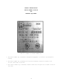
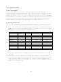
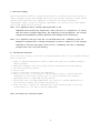
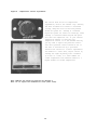
1
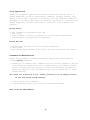
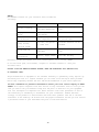
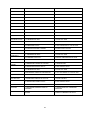
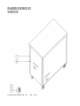
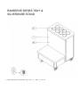
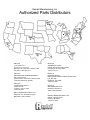
Randell Manufacturing, Inc.
This manual provides information on installation, operating, maintenance,
troubleshooting & replacement parts for
RANSERVE
MODULAR CAFETERIA LINES
NOTIFY CARRIER OF DAMAGE AT ONCE.
It is the responsibility of the consignee to inspect the container upon receipt of same and
to determine the possibility of any damage, including concealed damage. Randell
suggests that if you are suspicious of damage to make a notation on the delivery receipt.
It will be the responsibility of the consignee to file a claim with the carrier. We
recommend that you do so at once.
520 S. Coldwater Road Weidman, Ml 48893-9683
Phone 1-800-621-8560 Fax 1-800-634-5369 www.randell.com
TABLE OF CONTENTS
Page 2
Page 3
……………………………………………………………………Congratulations
…………………………………………………………..Factory Correspondence
Page 4
…………………………………………………………...Serial Number Location
Page 5
Page 8
………………………………………………………...Randell Limited Warranty
………………………………………………………Frequently Asked Questions
Page 9
……………………………………………………….Section I Refrigerated Units
Page 9
Page 13
………………………………………………………………...Unit Specifications
…………………………………………………………………...Unit Installation
Page 16
…………………………………………………………………….Unit Operation
Page 16
Page 18
…………………………………………………………Preventative Maintenance
…………………………………………………………………...Troubleshooting
Page 24
…………………………………………………………………Replacement Parts
Page 30
Page 30
…………………………………………………………Section II Hot Food Units
………………………………………………………………...Unit Specifications
Page 31
…………………………………………………………………...Unit Installation
Page 32
Page 32
…………………………………………………………………….Unit Operation
…………………………………………………………Preventative Maintenance
Page 33
…………………………………………………………………...Troubleshooting
Page 35
Page 38
…………………………………………………………………Replacement Parts
…………………………………………………….Section III Serving Equipment
Page 38
………………………………………………………………...Unit Specifications
Page 39
…………………………………………………………………Replacement Parts
Congratulations on your recent purchase of Randell food service equipment, and welcome
to the growing family of satisfied Randell customers.
Our reputation for superior products is the result of consistent quality craftsmanship.
From the earliest stages of product design, to successive steps in fabrication and
assembly, rigid standards of excellence are maintained by our staff of designers,
engineers, and skilled employees.
Only the finest heavy-duty materials and parts are used in the production of Randell
brand equipment. This means that each unit, given proper maintenance, will provide years
of trouble free service to its owner.
In addition, all Randell food service equipment is backed by one of the best warranties
in the food service industry and by our professional staff of service technicians.
2
Retain this manual for future reference.
Notice: Due to a continuous program of product improvement, Randell Manufacturing
reserves the right to make changes in design and specifications without
prior notice.
Notice: Please read the entire manual carefully before installation.
If certain recommended procedures are not followed, warranty claims will be denied.
Model Number
Serial Number
Installation Date
___________
___________
___________
Model Number
Serial Number
Installation Date
___________
___________
___________
Model Number
Serial Number
Installation Date
___________
___________
___________
Model Number
Serial Number
Installation Date
___________
___________
___________
Model Number
Serial Number
Installation Date
___________
___________
___________
Model Number
Serial Number
Installation Date
___________
___________
___________
Randell Manufacturing
Service and Parts Hot Line
1-800-621-8560
3
RANDELL MANUFACTURING
SERIAL NUMBER LOCATION
FOR
RANSERVE EQUIPMENT
This is a sample of a serial number tag
1. The serial number tag on Ranserve refrigerated equipment is located in the mechanical
housing.
2. The serial number tag on Ranserve hot food and silverware stand are located on the
far left front side of the unit.
3. The serial number tag on Ranserve cashier stands and cold pans are located on the far
left side.
4
Randell Manufacturing, Inc.
Warranty Policies
Parts Warranty
Randell warrants all component parts of manufactured new equipment to be free of defects
in material or workmanship, and that the equipment meets or exceeds reasonable industry
standards of performance for a period of one year from the date of shipment from any
Randell factory, assembly plant or warehouse facility.
Note:
Warranties are effective from date of shipment, with a thirty day window to allow
for shipment, installation and set up. In the event equipment was shipped to a
site other than the final installation site, Randell will warranty for a period of
three months following installation, with proof of starting date, up to a maximum
of eighteen months from date of purchase.
Component parts warranty does not cover glass breakage or gasket replacement. Randell
covers all shipping cost related to component part warranty sent at regular ground rates
(UPS, USPS). Freight or postage incurred for any express or specialty methods of shipping
are the responsibility of the customer.
Labor Coverage
In the unlikely event a Randell manufactured unit fails due to defects in materials or
workmanship within the first ninety days, Randell agrees to pay reasonable labor
incurred. During the first ninety days work authorizations are not required for in
warranty repairs. However, repair times are limited to certain flex rate schedules and
hours will be deducted from service invoices if they exceed allowed times without prior
approval and a work authorization number. Warranties are effective from date of shipment,
with a 30 day window to allow for shipment, installation and setup.
Where equipment is shipped to any site other than final installation Randell will honor
the labor warranty for a period of ninety days following installation with proof of
starting date, up to a maximum of nine months from date of purchase. Travel time is
limited to one hour each direction or two hours per invoice. Any travel time exceeding
two hours will be the responsibility of the customer.
Note: Temperature adjustments are not covered under warranty, due
to the wide range of ambient conditions.
5
Five Year Extended Compressor Warranty
United States installations only:
Randell will pay for the replacement compressor only. Freight, labor, refrigerant,
handling and all other miscellaneous charges are the responsibility of the customer.
Randell will fulfill its warranty obligation by using one of the four methods provided
below, which will be selected by the Randell in-house service technician:
1. Provide reimbursement to servicing customer for the cost of the locally obtained
replacement compressor in exchange for the return of the defective compressor returned
to Randell freight prepaid. Randell does limit the amount of reimbursement allowed and
does require a copy of the local supply house bill for replacement compressor.
Customer should not pay servicing agent up front for compressor.
2. Provide repair at the manufacturing facility by requiring that the defective unit be
sent back to Randell freight prepaid. Perform repair at the expense of Randell and
ship the item back to job location freight collect.
3. Furnish a replacement compressor freight collect in exchange for the return of the
defective compressor sent back freight prepaid.
4. Furnish complete condensing unit or replacement package
freight collect in exchange for the return of the defective compressor sent back
freight prepaid, (decisions based on whether or not to send complete condensing unit
will be made by Randell in-house service technician).
Export Warranty
Our export warranties will cover all non electrical parts for the period of one year from
the date of shipment to be free of defects in material or workmanship. Electrical parts
are also covered if ordered and operated on 60 Hz. Electrical components, ordered and
operated on 50 Hz, are warranted for the first 90 days from shipment only. Service labor
is covered for the first 90 days with authorization from factory prior to service.
Warranty is automatically initiated 60 days from ship date. Inbound costs on any factory
supplied items would be the responsibility of the customer. Adherence to recommended
equipment maintenance procedures, according to the owners manual provided with each unit,
is required for this warranty to remain in effect, and can have a substantial effect on
extending the service life of your equipment. Equipment abuse voids any warranty.
Extended warranties are not available for parts, labor or compressors on units shipped
outside the United States.
6
Freight Damage
Any and all freight damage that occurs to a Randell piece of equipment as a result of
carrier handling is not considered warranty, and is not covered under warranty
guidelines. Any freight damage incurred during shipping needs to have a freight claim
filed by the receiver with the shipping carrier (note all damages on freight bill at time
of delivery) . Internal or concealed damage may fall under Randell's responsibility
dependent upon the circumstances surrounding each specific incident and are at the
discretion of the Randell in-house service technician.
Gasket Coverage
Randell does not cover gaskets under warranty. Gaskets are a maintenance type component
that are subject to daily wear and tear and are the responsibility of the owner of the
equipment. Because of the unlimited number of customer related circumstances that can
cause gasket failure all gasket replacement issues are considered non-warranty. Randell
recommends thorough cleaning of gaskets on a weekly basis with a mild dish soap and warm
water. With proper care Randell gaskets can last up to two years, at which time we
recommend replacement of all gaskets on the equipment for the best possible performance.
NOTICE: FOOD LOSS IS NOT COVERED UNDER WARRANTY
7
SECTION I - RANSERVE REFRIGERATED EQUIPMENT
Unit Specifications
For The
Ranserve FRA Series
FRA SERIES
MODEL
RAN FRA-1
RAN FRA-2
L
D
H
STORAGE
CU. FT.
24" 27" 35"
1.8
36" 27" 35"
3.6
GALLON HP
VOLT
CAPACITY
6
1/3 115/60/1
12
1/3 115/60/1
9
AMP NEMA
6.3
6.3
5-15P
5-15P
SHIP
WT.
200
230
Unit Specifications
For The
Ranserve SCA Series
SCA Series & SCA "S" SERIES
MODEL
L
D
H
12X20 PAN
HP
VOLT/Hz/Ph
AMPS
NEMA SHIP
CAPACITY
WT
COLDPAN
INTERIOR
DIMENSIONS
RAN SCA-3
48"
27"
35"
3
1/3
115/60/1
6.5
5-15P
175 37 7/8" X 19 7/8X6"
RAN SCA-4
60"
27"
35"
4
1/3
115/60/1
6.5
5-15P
215 51 7/8" X 19 7/8X6"
RAN SCA-5
78"
27"
35"
5
1/3
115/60/1
6.5
5-15P
260 66 7/8" X 19 7/8X6"
The "S" series has an open base.
10
Unit Specifications
For The
Ranserve FTA Series
FTA & FTA "S" Series
MODEL
L
D
H
HP
VOLT/Hz/Ph
AMPS
NEMA
SHIP WT
RAN FTD-3
48"
27"
35"
1/3
115/60/1
6.5
5-15P
225
RAN FTD-4
60"
27"
35"
1/3
115/60/1
6.5
5-15P
265
RAN FTD-5
78" 27" 35" 1/3
115/60/1
The FTA "S" series has an open base.
6.5
5-15P
310
11
Unit Specifications
For The
Ranserve IC Series
MODEL
RAN IC-3
RAN IC-4
RAN IC-5
L
D
H
48"
60"
78"
27"
27"
27"
35"
35"
35"
12" X 20" PAN
CAPACITY
3
4
5
COLD PAN INTERIOR
DIMENSIONS
37.875" X 19.875" X 6"
51.875" X 19.875" X 6"
66.875" X 19.875" X 6"
SHIP
WT
175
215
260
"S" Series not shown has the same specifications as standard IC, but with open
base below.
12
Unit Installation
A. Receiving Shipment
Upon arrival, examine the exterior of the shipping crate for signs of abuse. It is
advisable that the shipping crate be partially removed, in order to examine the cabinet
for any possible concealed damages which might have occurred during shipment. If no
damages are evident, replace the crate in order to protect the unit during storage and
local delivery. If the unit is damaged, it should be noted on the delivery slip or bill
of lading and signed to that effect. A claim must be filed immediately against the
carrier indicating the extent and estimated cost of damage occurred.
B. Locating Your New Unit
The following conditions should be considered when selecting a location for your unit:
1. Floor - The area on which the unit will rest must be free of vibration and suitably
strong enough to support the combined weights of the unit plus the maximum product
load weight, which are provided in the table below:
MODEL
RAN FRA-1
RAN FRA-2
RAN SCA-3
RAN SCA-4
RAN SCA-5
RAN FTD-3
RAN FTD-4
RAN FTD-5
RAN IC-3
RAN IC-4
RAN IC-5
CUBIC FT
1.8
3.6
6
8
10
N/A
N/A
N/A
6
8
10
FACTOR
35
35
35
35
35
N/A
N/A
N/A
35
35
35
WEIGHT POUNDS
200
230
175
215
260
225
265
310
175
215
260
TOTAL CAPACITY
263
356
385
495
610
225
265
310
385
495
610
2. Clearance - There must be a combined total of at least 3" clearance on all sides of
the unit.
3. Ventilation - The air cooled self contained unit requires a sufficient amount of
cool clean air. Avoid placing the unit near heat generating equipment such as ovens,
ranges, heaters, fryers, steam kettles, etc. and out of direct sunlight. Avoid
locating the make table in an unheated room or where the room temperature may drop
below 55° F or above 90° F.
13
C. Electrical Supply
The wiring should be done by a qualified electrician in accordance with local electrical
codes. A properly wired, and grounded outlet will assure proper operation. Please consult
the data plate attached to the compressor to ascertain the correct electrical
requirements. Supply voltage and amperage requirements are located on the serial number
tag located inside the far left door.
Note: It is important that a voltage reading be made at the
compressor motor electrical connections, while the unit is in operation, to verify
that the correct voltage required by the compressor is being supplied. Low or high
voltage can detrimentally affect operation and thereby void its warranty.
Note: It is important that your unit has its own dedicated line. Condensing units are
designed to operate with a voltage fluctuation of plus or minus 10% of the voltage
indicated on the unit data plate. Burn out of a condensing unit due to exceeding
voltage limits will void the warranty.
E. Installation Checklist
After the final location of the unit has been determined refer to the following checklist
prior to start up:
1. Check all exposed refrigeration lines to ensure that they are not kinked, dented or
rubbing together.
2. Check that condenser fans rotate freely without striking any stationary members.
3. Unit must be properly leveled.
4. Plug in unit.
5. Turn on cold control located by the compressor.
6. Refer to the front of this manual for serial number location. Please record this
information in your manual on page 3 now. It will be necessary when ordering
replacement parts or requesting warranty service.
7. Confirm that unit is holding temperature. Set controls to desired temperature for
your particular ambient and altitude (See figure A.).
8. Allow your unit to operate for approximately 2 hours before putting in food this
allows interior to cool down to storage temperature.
Note: All motors are oiled and sealed.
14
Figure A - Temperature control adjustments
The control knob allows for temperature
adjustments, with in the cabinet only. Turning
the knob clockwise will result in increased
cooling. Keep the arrow on the knob pointed
within the green arc. Turning it clockwise
beyond the green can result in freeze-up, while
turning it counterclockwise beyond the green
will shut the compressor off. If your cabinet
temperature remains to warm and your
temperature control is at the maximum setting
you may need to adjust the pressure control.
Your units pressure control should be set at
the time of installation by a qualified
installation contractor. If minor adjustments
are needed at a later date, adjust control by
turning the right adjusting screw clockwise
(1/4 turn at a time) to a lower number for
colder temperature and counterclockwise to a
higher number for warmer temperature.
Note: Numbers are pounds of pressure not degrees F.
Note: Do not adjust the differential screw (Left screw).
15
Unit Operation
Randell has attempted to preset the cold control to ensure that your unit runs at an
optimum temperature, but due to varying ambient conditions, including elevation, food
product as well as type of operation you may need to alter this temperature. Additional
adjustments can be made (within limits) by turning the control dial up or down until the
desired temperature is reached. control dial is located next to the compressor (see
figure A).
Morning Startup
1.
2.
3.
4.
Unit cleaning may be performed at this time.
Turn on unit.
Allow 45 minutes to one hour for your unit to cool down before loading product.
Load the product and proceed with food preparation.
Evening Shut Down
1. Remove product from unit at the end of the day's preparation.
2. Turn off unit.
3. Unit cleaning maybe performed at this time if the frost has melted off the surface.
Preventive Maintenance
Randell strongly suggests a preventive maintenance program which would include the
following Monthly procedures:
1. Cleaning of all condenser coils. Condenser coils are a critical component in the life
of the compressor and must remain clean to assure proper air flow and heat transfer.
Failure to maintain this heat transfer will affect unit performance and eventually
destroy the compressor. Clean the condenser coils with coil cleaner and/or a vacuum
cleaner and brush.
Note: Brush coil in direction of fins, normally vertically as to not damage or restrict
air flow from passing through condenser.
2. Clean fan blade on the condensing.
3. Clean and disinfect drains with a solution of warm water and bleach.
NOTE: DO NOT USE SHARP UTENSILS
16
TABLE 1
Recommended cleaners for your stainless steel include the
following:
JOB
CLEANING AGENT
COMMENTS
Routine cleaning
Soap, ammonia,
detergent Medallion
Apply with a sponge or
cloth
Fingerprints and
smears
Stubborn stains and
discoloration
Arcal 20,Lac-0Nu,Ecoshine
Cameo, Talc, Zud,
First impression
Provides a barrier film
Greasy and fatty
acids, blood,
burnt-on foods
Easy-Off, De-grease
It, Oven aid
Excellent removal on all
finishes
Grease and oil
Any good commercial
detergent
Apply with a sponge or
cloth
Restoration/
Passivation
Benefit, Super Sheen
Good idea monthly
Rub in the direction of
the polish lines
Reference: Nickel Development Institute, DiverseyLever, Savin, Ecolab, NAFEM
Do not use steel pads, wire brushes, scrapers or chloride cleaners to clean your
stainless steel.
CAUTION: DO NOT USE ABRASIVE CLEANING SOLVENTS, NEVER USE HYDROCHLORIC ACID (MURIATIC ACID)
ON STAINLESS STEEL.
Proper maintenance of equipment is the ultimate necessity in preventing costly repairs. By
evaluating each unit on a regular schedule you can often catch and repair minor problems
before they completely disable the unit and become burdensome on your entire operation.
For more information on preventive maintenance consult your local service company or CEFSA
member. Most repair companies offer this service at very reasonable rates to allow you the
time you need to run your business along with the peace of mind that all your equipment
will last throughout its expected life. These services often offer guarantees as well as
the flexibility in scheduling of maintenance for your convenience. Randell believes
strongly in the products it manufacturers and backs those products with one of the best
warranties in the industry. We believe with the proper maintenance and use you will realize
a profitable return on your investment and years of satisfied service.
17
SYMPTOM
POSSIBLE CAUSE
PROCEDURE
UNIT DOESN'T RUN
1. NO POWER TO UNIT.
1. PLUG IN UNIT.
2. TEMPERATURE CONTROL TURNED OFF.
2. CHECK TEMPERATURE CONTROL.
3. TEMPERATURE CONTROL FAULTY.
3. TEST TEMPERATURE CONTROL. SEE #4
4. COMPRESSOR OVERHEATED.
4. CLEAN CONDENSER COIL. SEE#1
5. CONDENSER FAN FAULTY.
5. SERVICE CONDENSER FAN MOTOR SEE #4
6. OVERLOAD PROTECTOR FAULTY.
6. TEST OVERLOAD. SEE #6
7. COMPRESSOR RELAY FAULTY.
7. TEST RELAY. SEE #6
8. COMPRESSOR FAULTY.
8. CALL FOR SERVICE AT 1-800-621-8560.
1. CONDENSER COIL DIRTY.
1. CLEAN COIL. SEE#1
2. CONDENSER FAN FAULTY.
2. SERVICE FAN AND MOTOR. SEE #4
3. COMPRESSOR FAULTY.
3. CALL FOR SERVICE AT 1-800-621-8560.
4. OVERLOAD REPEATEDLY TRIPPING.
4. CHECK OUTLET VOLTAGE.
1. CONDENSER COIL DIRTY.
1. CLEAN COIL. SEE#1
4. CONDENSER FAN FAULTY.
4. SERVICE CONDENSER MOTOR. SEE #4
1. TEMPERATURE CONTROL SET TOO HIGH.
1. LOWER SETTING.
2. TEMPERATURE CONTROL FAULTY.
2. TEST CONTROL. SEE #4
3. CONDENSER COIL DIRTY.
3. CLEAN COIL. SEE#1
8. REFRIGERANT LEAKING OR CONTAMINATED.
8. CALL FOR SERVICE AT 1-800-621-8560.
1 TEMPERATURE CONTROL SET TOO LOW.
1. ADJUST CONTROL.
2. TEMPERATURE CONTROL FAULTY.
2. TEST CONTROL. SEE #4
1. COMPRESSOR MOUNTINGS LOOSE OR
HARDENED.
1. TIGHTEN OR REPLACE COMPRESSOR
MOUNTINGS.
2. CONDENSER FAN DAMAGED OR HITTING FAN
SHROUD.
2. INSPECT CONDENSER FAN. SEE # 9
UNIT SHORT CYCLES
UNIT RUNS
CONSTANTLY
UNIT NOT COLD
ENOUGH
UNIT TOO COLD
UNIT NOISY
19
1. Cleaning condenser coil.
An accumulation of dirt and dust prevents the
condenser coil from removing heat, making your
unit cool poorly, run constantly, or even stop
completely if the compressor overheats. Clean coil
using a vacuum cleaner with a wand attachment. If
the coil is greasy, wash it with warm soapy water
and a bristle brush, taking care not to drip water
on other parts of your unit.
2. Cleaning drain.
Clean the drain using an oven baster to force a solution of hot water and baking soda or
bleach into the opening.
3. Testing and replacing the temperature control.
Unplug the unit and remove the temperature control knob. Remove the screws securing the
fan shroud to the evaporator coil assembly, next remove the screws securing the
temperature control to the fan shroud. Taking care not to bend the capillary line, pull
off the wire connectors. Now you are ready to test for continuity.
Set your multimeter at RX1, Touch a probe to each
terminal. With the control at its the tester should
indicate a closed circuit. Turn off the control
then retest; the tester should indicate an open
circuit. To install a new temperature control, pull
the capillary line of the old control out of its
opening. Set the new control to its coldest setting
and carefully thread the capillary line into the
opening without kinking it. Attach the wires to the
terminals, screw the control in place and reattach
the dial.
20
4. Servicing the condenser fan.
Inspect the condenser fan motor by removing the mechanical housing cover to gain access.
Unplug the unit. Clean the fan blade, and turn it to see if the blade rotates freely. If
the motor binds, replace it. If the blade is damaged, unscrew the nut that holds it to
the motor shaft and pull it off. Install a new fan blade, replacing any washers, and
tighten the nut.
To test the condenser fan motor disconnect the
wires to the fan motor. Set a multimeter at RX10
and touch one probe to each terminal. The
multimeter needle should show approximately 45 to
50 ohms resistance; a lower reading means the
motor is faulty. Next set the meter at RX1000 and
touch one probe to the motor terminals and the
other one to any unpainted metal part of the unit.
If the meter needle moves, the motor is grounded
and should be replaced. To remove the motor
unscrew the bracket that holds the
fan motor to its housing, slide the motor out of
the housing. Remove the fan blade from the old
motor and attach it to the new motor, replacing
any washers. Install the new motor in its housing
by screwing the bracket in place. Reattach the
wires to the motor terminals.
5. Servicing the compressor.
The compressor is part of the sealed
refrigeration system and should be replaced by a
professional service technician. You can,
however, test the compressor and certain
components. Unplug the unit and remove the access
cover to the mechanical housing. A small box
mounted on the side of the compressor protects
the relay, overload protector and capacitor.
Release the wire retaining clip that holds the
cover in place and slip off the cover and the
clip.
21
6. To test the compressor relay pull the relay
straight off the compressor without twisting it.
If the relay has an external wire coil, hold the
relay so that the word top is up. Set the
multimeter at RX1 and place the probes on the
terminals S and M. the multimeter needle should
not move. Next remove the probe from M and place
it on the side terminal marked L. once again, the
needle should not move. Finally, remove the
probe from S and place it on M. the needle should
sweep across the scale, showing full continuity.
Now turn the relay upside down and perform the
same tests. You should get the opposite results: continuity between terminals S and M and
between S and L; no continuity between M and L. if the relay fails any of these tests,
replace it: push the new relay onto the compressor terminals and replace the terminal
cover. If the relay passes these tests, test the overload protector.
7. To remove the overload protector use a screwdriver to gently pry open the circular
spring clip that secures the overload protector to the compressor and snap out the
protector. Pull the two wire connectors off their terminals.
8.
To test set a multimeter at RX1 and touch a
probe to each overload protector terminal. The
multimeter needle should sweep across the
scale, showing full continuity. If the overload
protector passes this test, test the
compressor. If not replace the overload
protector. Reattach the push-on connectors to
the new overload protector, clip it in place on
the compressor and replace the terminal cover.
22
9. To test the compressor set a multimeter
at RX1, test each of the three terminal pins
against each of the other two. Each pair
should show continuity. Then, with the
multimeter set at RX1000, place one probe
against the metal housing of the compressor;
if necessary, scrape off a little paint to
ensure contact with bare metal. Place the
other probe on each of the three terminals
in turn. If any of the three terminals shoes
continuity with the housing, the compressor
is grounded. If the compressor fails either
test, call for service. If it passes the
tests, reinstall the overload protector,
relay, terminal cover and mechanical housing
cover.
23
RANSERVE SERIES
ITEM DESCRIPTION
PART#
COLD FROST FREEZER
IC
PAN
TOP
UNIT
x
x
x
x
3
CASTER SET
001450
4
NON LOCKING CASTER
HD CST3050
x
x
x
x
5
LOCKING CASTER
HD CST3051
x
x
x
x
7
STAINLESS STEEL PANEL, SPECIFY
DIMENSIONS
RP PNL001
x
x
x
x
17
POWER CORD
ELWIR461
x
x
x
x
102
LOUVER
RP LVRSCF
x
x
102A
LOUVER
RP LVRFRA
108
EXPANSION VALVE
RFVLV134A18Z
108
EXPANSION VALVE
RF VLV408
109
MALE POWER CORD
EL WIR469
x
x
x
110
FEMALE POWER CORD
EL WIR471
x
x
x
112
CAP TUBE .042 120"
RF CAP003
116
THERMOSTAT RANCO
HDCNT100
THERMOSTAT HIGH TEMP ADJ. RANGE
HD CNT225
117
PRESSURE CONTROL DUAL
HD CNT725
121
ACCUMULATOR
RF ACM005
x
130
CONDENSING UNIT, AEA2410YX
RF CON495
x
CONDENSING UNIT, AEA2413Z
RF CON254
131
COMPRESSOR
RF CMP495
131A
COMPRESSOR
RF CMP031
134
START COMPONENTS
RF STR495
134A
START COMPONENTS
RF STR254
135
RECEIVER TANK
RF TNK254
136
CONDENSER COIL
RF COI495
136
CONDENSER COIL
RF COI254
137
CONDENSER FAN W\BLADE
RF FAN001
138
CONDENSE FAN BLADE ONLY
140
FILTER DRIER
141
116A
130A
x
x
x
x
x
x
x
x
x
x
x
x
x
x
x
x
x
x
x
x
x
x
x
RF FAN495
x
x
x
RF FLT250A
x
x
x
CONDENSATE EVAP PAN
RP PAN RAN
x
x
x
210
ADAPTER BAR
RP BAR020
x
220
COVER, INSULATED HINGED
HDLID111
x
223
HINGE, INSULATED COVER
HD LID001
x
230
ROCKER SWITCH
EL SWT200
x
231
COLD PAN DRAIN 1" BRASS
HDDRN100
x
233
INSERTS, PERFORATED
RP INS001
232
COLD PAN DRAIN SCREEN
RP DSC001
316
HANDLE, EXTENDED BALL VALVE
RP HDLHTD
614
DRAIN VALVE 1" BALL VALVE
PB VLV650
25
x
x
x
x
x
x
o:/drafting/service/ranserve.dgn
Sep.
1, 1998
09:37:46
or/drafting/service/ranserve.dgn
Sep.
1, 1998
09:38:50
o:/drafting/service/ranserve.dgn
Sep.
1, 1998
09:39:10
MODEL RANSERVE SERIES
REFRIGERATOR PARTS DIAGRAM
SECTION II - RANSERVE HOTFOOD EQUIPMENT
Unit Specifications
For The
Ranserve HTD Series
HTD SERIES
MODEL
RAN HTD-2
RAN HTD-3
RAN HTD-4
RAN HTD-5
RAN HTD-2B
RAN HTD-3B
RAN HTD-4B
RAN HTD-5B
MODEL
L
D
H
RAN HTD-2
RAN HTD-3
RAN HTD-4
RAN HTD-5
RAN HTD-2 B
RAN HTD-3B
RAN HTD-4B
RAN HTD-5B
30"
48"
60"
72"
30"
48"
60"
72"
27"
27"
27"
27"
27"
27
27
27
35"
35"
35"
35"
35"
35"
35"
35"
#OF
WELLS
# OF
ELEMENTS
2
3
4
5
2
3
4
5
2
3
4
5
3
4
5
6
120V
SHIP
WT.
175
215
260
325
175
215
260
325
208V
240V
kW
AMP
NEMA
kW
AMP
NEMA
kW
AMP
NEMA
2.2
3.3
4.4
5.5
3.3
4.4
5.5
N/A
18.4
27.6
36.8
46
27.6
36.8
46
N/A
5-30P
5-50P
5-50P
N/A
5-50P
5-50P
N/A
N/A
2.2
3.3
4.4
5.5
3.3
4.4
5.5
6.6
10.6
15.9
21.2
27.5
15.9
21.2
27.5
31.7
6-15P
6-20P
6-30P
6-50P
6-20P
6-30P
6-50P
6-50P
2.2
3.3
4.4
5.5
3.3
4.4
5.5
6.6
9.2
13.8
18.4
23
13.8
18.4
23
27.5
6-15P
6-20P
6-30P
6-30P
6-20P
6-30P
6-30P
6-50P
“S" series not shown has the same specifications as standard HTD.
30
Unit Installation
A. Receiving Shipment
Upon arrival, examine the exterior of the shipping crate for signs of abuse. It is
advisable that the shipping crate be partially removed, in order to examine the unit for
any possible concealed damages which might have occurred during shipment. If no damages
are evident, replace the crate in order to protect the unit during local delivery. If
the unit is damaged, it should be noted on the delivery slip or bill of lading and
signed to that effect. A claim must be filed immediately against the carrier indicating
extent and estimated cost of damage incurred.
B. Electrical Supply - The wiring should be done by a qualified electrician in accordance
with local electrical codes. A properly wired, and grounded outlet will assure proper
operation. Please consult the data plate to ascertain the correct electrical
requirements. Supply voltage requirements are on the unit serial number tag.
Note: It is important to verify that the correct voltage.
Supplying the incorrect voltage can detrimentally affect the unit and thereby void
its warranty.
Note: It is important that your unit have its own dedicated line;
hot food holding units are designed to operate with a voltage fluctuation of
plus or minus 10% of the voltage indicated on the unit data plate. Burnout of
electrical components due to exceeding voltage limits will void the warranty.
Warning: Improper installation, adjustment, alteration, service or maintenance can cause
injury or property damage. Refer to this manual for assistance or consult a
qualified installer, service agency, or dealer.
31
Unit Operation
All units are designed for 145 to 175° operation or 140 to 170° product temperature. When
using the unit dry expect at least a 15° drop in product temperatures compared to using
it wet. Hot food tables may be operated utilizing water or dry. However wet operation is
usually recommended for higher efficiency.
Plumbing: The units drain must have an outlet to an appropriate drainage area or
container.
Note: Drains must be plumbed to all applicable local code requirements.
Caution: Moisture collecting from improper drainage can create a slippery surface on the
floor and a hazard to employees. When making electrical connections refer to the
amperage data listed on the units data plate. Your local code or the national
electrical code handbook to be sure the unit is connected to the proper power
source.
Preventive Maintenance
Randell strongly suggests a preventive maintenance program which would include the
following monthly procedures:
1. Clean your hot food table with a solution of warm water and a mild detergent. The
stainless steel portions of your unit can be polished with any quality polish.
2. Drain water from wells daily and wipe them out. Clean wells thoroughly twice a week
to help insure a longer life for your wells.
3. Visually check the color of the burner flames every 6 months. To adjust the flow of
air to the burner, loosen the Phillips head screw and rotate the shutter to allow
more or less air into the burner tube as needed. The flames should burn steady with
approximately 1" blue cones and should not extend out over the edges of the pan
diverter.
Note: Do not use chemicals, steel wool or scrapers to clean unit
CAUTION: DO NOT USE ABRASIVE CLEANING SOLVENTS.
NOTE: FOR MORE INFORMATION ON CLEANING YOUR HOTFOOD UNIT SEE TABLE 1.
32
Proper maintenance of equipment is the ultimate necessity in preventing costly repairs.
By evaluating each unit on a regular schedule you can often catch and repair minor
problems before they completely disable the unit and become burdensome on your entire
operation.
For more information on preventive maintenance consult your local service company. Most
repair companies offer this service at very reasonable rates to allow you the time you
need to run your business along with the piece of mind that all your equipment will last
throughout its expected life. These services often offer guarantees as well as the
flexibility in scheduling of maintenance for your convenience.
Randell believes strongly in the products it manufactures, and backs those products with
one of the best warranties in the industry. We believe with proper maintenance and use
you will realize a profitable return on your investment and years of satisfied service.
Troubleshooting
Electrical:
PROBLEM
Unit will not heat.
Individual well will not heat.
POSSIBLE CAUSE
1. Thermostat off.
2. Unit unplugged.
3. Circuit breaker tripped.
4. Thermostat defective.
5. Unknown.
1. Thermostat off.
2. Thermostat defective.
3. Defective element.
4. Unknown.
33
REMEDY
1. Turn on thermostat.
2. Plug in unit.
3. Reset or replace circuit breaker.
4. Test and/or replace thermostat see fig. 1.
5. Call 1-800-621-8560 for service agency.
1. Turn on thermostat.
2. Test and/or replace thermostat see fig. 1
3. Test and/or replace element.
4. Call 1-800-621-8560 for service agency
Figure 1
Set your multimeter at RX1, Touch a probe to each
terminal. With the control at its Coldest setting, the
tester should indicate a closed circuit. Turn off the
control then retest; the tester should indicate an open
circuit. To install a new temperature control, pull the
capillary line of the old control out of its opening. Set
the new control to its Coldest setting and carefully
thread the capillary line into the opening without
kinking it. Attach the wires to the terminals, screw the
control in place and reattach the dial.
Figure 2
Testing the element.
Unplug the unit. Pull the wires from the
terminal ends of the element. Set the
multimeter at RX1 and attach a probe to
each terminal end. The meter should show
medium resistance. If not replace the
element.
Figure 3
Testing the element for ground.
Unplug the unit. Pull the wires from the
terminal ends of the element. Set the
multimeter at RX1 and attach one probe to
one terminal end and the other to the metal
sheath of the element; The meter needle
should not move. If the needle moves replace
the element.
34
RANSERVE SERIES HOTFOOD
ITEM
DESCRIPTION
PART#
3 CASTER SET
001450
4 NON LOCKING CASTER
HD CST3050
5 LOCKING CASTER
HD CST3051
7 STAINLESS STEEL PANEL, SPECIFY DIMENSIONS
RP PNL001
17 POWER CORD W/PLUG SPECIFY VOLTAGE & WATTAGE
EL WIRSPC
40 DOOR RIGHT HAND
RP DORHTDR
41 DOOR LEFT HAND
RP DORHTDL
44 GASKET, 15" X 15 3/8"
IN GSK149
44A GASKET, 15" X 27 3/8"
INGSK153
46 HINGE ASSEMBLY DOOR
HD HNG300
47 HANDLE RECESSED, DOOR
HDHDL1012
49 LOCK W/KEY
HD LCK0490
57 SLIDING DOOR TRACK, GUIDE
RP GDE001
116 THERMOSTAT
EL HFT230
301 HEATING ELEMENT, 120V 1100W
ELELM1100
301A HEATING ELEMENT, 208V 1100W
ELELM1172
301B HEATING ELEMENT, 240V 1100W
ELELM1124
301C STRIP HEATER OGDEN 1000W, 240V
EL HTR750
303 ELEMENT PAN
RP PANHTD
310 CONTROL KNOB
HD CNT230
314 HFW DRAIN SCREEN
RP SCN001
316 EXTENDED BALL VALVE HANDLE
RP HDLHTD
599 INDICATOR LIGHT
EL LGT500
602 BALL VALVE
PB VLV650
721 SPRING
HDSPR017
36
o:/drafting/service/ranserve.dgn
Sep.
1, 1998
09:38:27
SECTION III - RANSERVE SERVING EQUIPMENT
Unit Specifications
For The
Ranserve Serving Equipment
&
COUNTER PROTECTORS
SERVING
EQUIPMENT
L
D
H
NUMBER OF 5.25" DIA.
VERTICAL SILVERWARE
BINS
SHIP
WT.
RAN CA
30"
27"
35"
N/A
135
RAN SW-8
30"
27"
35"
8
110
RAN SW-12
RAN ST-2
36"
24"
27"
27"
35"
35"
12
N/A
120
100
RAN ST-3
36"
27"
35"
N/A
125
RAN ST-4
RAN ST-5
48"
60"
27"
27"
35"
35"
N/A
N/A
150
175
RAN ST-6
72"
27"
35"
N/A
200
MODEL
38
RANSERVE SERIES
3 CASTOR SET
001450
X
X
TRAY&
SILVER
WARE
X
4 NON LOCKING CASTOR
HD CST 3051
X
X
X
5 LOCKING CASTOR
HD CST 3050
X
X
X
STAINLESS STEEL PANEL, SPECIFY
7 DIMENSIONS
RP PNL001
X
X
X
27 PERFORATED SILVERWARE INSERT
HDINS100
X
HD PAN01Y
X
ITEM
DESCRIPTION
27A SILVERWARE INSERT PAN
PARTS
CASHIER
STAND
49 LOCK ASSY, DRAWER
HD LCK505
X
60 DRAWER ASSEMBLY
RPDWR1CA
X
63 DRAWER TRACK, S35-1020
HD TRK 004
X
69 HANDLE, DRAWER 4"
HD HDL010
X
RP PNL002
X
94
LAMINATE PANEL, SPECIFY DIMENSIONS, MFG
OF LAMINATE, COLOR AND COLOR CODE
COUNTER
PROTECTOR
X
407 GLASS W/FRAME, SPECIFY DIMENSIONS
HD GLS001
X
COUNTER PROTECTOR FRAME WORK,
411 SPECIFY PARTICULAR MODEL OR TYPE
RP FRM001
X
412 BRACKET ADJ. SNEEZEGUARD
HDBRK215
X
40
S/S
WORK
X
o:/drafting/service/ranserve.dgn
Sep.
1, 1998
09:37:26
RANSERVE SERIES S/S
WORKTOP
o:/drafting/service/ranserve.dgn
Sep.
1, 1998
09:37:04
RANSERVE SERIES TRAY &
SILVERWARE STAND
o:/drafting/service/ranserve.dgn
Aug. 31, 1998
11:15:54
Randell Manufacturing, Inc.
Authorized Parts Distributors
DEPOT #1
CASE PARTS CO.
877 Monterey Pass Road
Monterey Park, CA 91754 1-800-621-7884
(CA ONLY) 1-800-421-0271
DEPOT #2
REFRIGERATION HARDWARE SUPPLY
632 Foresight Circle
Grand Junction, CO 81505 1-800-423-2446
1-800-537-8300 (PAC. COAST)
DEPOT #5
COMMERCIAL PARTS
5310 E. 25th Street P.O. Box 18688
Indianapolis, IN 46218-0688
1-800-727-8710
DEPOT #6
HARRISON SUPPLY
Ridley Creek Plaza 5153 West Chester Pike
P.O. Box 596
Edgemont, PA 19028
1-800-521 -8444
DEPOT #3
STOVE PARTS SUPPLY
2120 Solona St.
Ft.Worth, TX 76117-0009
1-800-433-1804
DEPOT #4 GENERAL PARTS 11311
Hampshire Ave. South Bloomington,
MN 55438 1-800-279-9980
DEPOT #7
WHITESIDE PARTS 722
Brookhaven Orlando, FL
32803 1-800-322-2678
¶
RANDELL MANUFACTURING., INC.
0520 S. Coldwater Road
Weidman, Ml 48893
1-800-621 -8560