1
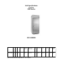
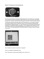
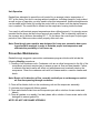
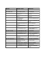
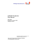
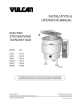
Randell Manufacturing, Inc.
OWNERS MANUAL
This manual provides information on installation, operating, maintenance, troubleshooting
&
replacement parts
for
JACK IN THE BOX
MODEL 2010FMJB
REACH-IN
NOTIFY CARRIER OF DAMAGE AT ONCE.
It is the responsibility of the consignee to inspect the container upon receipt of same and to
determine the possibility of any damage, including concealed damage. Randell suggests
that if you are suspicious of damage to make a notation on the delivery receipt. It will be
the responsibility of the consignee to file a claim with the carrier. We recommend that you
do so at once.
520 S. Coldwater Road Weidman MI 48893-9683
Phone 1-800-621-8560 Fax 1-800-634-5369
www.randell.com
CREATED MAY 10,2001
PP MNL0024
TABLE OF CONTENTS
Page 2 …………………………………………………………Congratulations
Page 3 …………………………………………….. Factory Correspondence
Page 4 ………………………………………………. Serial Number Location
Page 5 ……………………………………………………. Unit Specifications
Page 8 …… ……………………………………… Randell Limited Warranty
Page 11 ……………………… ……………………………… Unit Installation
Page 15 ……………………………………………………… Unit Operation.
Page 15……………………………………………Preventative Maintenance
Page 17……………………………………………………… Troubleshooting
Page 26 ………………………………………………………… Part Figures
Page 43 ……………
………………… Appendix A Heated Reach-ins
Congratulations on your recent purchase of Randell food service equipment, and welcome
to the growing family of satisfied Randell customers.
Our reputation for superior products is the result of consistent quality craftsmanship. From
the earliest stages of product design, to successive steps in fabrication and assembly, rigid
standards of excellence are maintained by our staff of designers, engineers, and skilled
employees.
Only the finest heavy-duty materials and parts are used in the production of Randell brand
equipment. This means that each unit, given proper maintenance, will provide years of
trouble free service to its owner.
In addition, all Randell food service equipment is backed by one of the best warranties in
the food service industry and by our professional staff of service technicians.
Retain this manual for future reference.
Notice: Due to a continuous program of product improvement, Randell Manufacturing
reserves the right to make changes in design and specifications without prior notice.
Notice: Please read the entire manual carefully before installation.
If certain recommended procedures are not followed, warranty claims will be denied.
Model Number
___________________________
Serial Number
___________________________
Installation Date ___________________________
Randell Manufacturing
Service and Parts
Hot Line
1-800-621-8560
RANDELL MANUFACTURING
SERIAL NUMBER LOCATION
FOR THE
2000 SERIES
This is a sample of a serial number tag.
The serial number tag on the 2000 series is located inside the refrigerated base on the far
left side of the unit.
Unit Specifications
For The
2000 Series
2010 SERIES
MOD EL
L
D
2010FMJB 30" 31"
H
DO O RS
69" 2
CUBIC
FEET
SHELVES
Q TY/SQ . FT
HP
BTU/HR VO LT
AMP
N EMA SHIP
WT
20.6
4/15.25'
½
2180*
9.3
5- 15P
*Based on 90F ambient evaporator for -10F freezers
115/60/1
375
Randell Manufacturing, Inc.
Warranty Policies
Parts Warranty
Randell warrants all component parts of manufactured new equipment to be free of defects
in material or workmanship, and that the equipment meets or exceeds reasonable industry
standards of performance for a period of one year from the date of shipment from any
Randell factory, assembly plant or warehouse facility.
Note: Warranties are effective from date of shipment, with a thirty day window to
allow for shipment, installation and set up. In the event equipment was shipped to a
site other than the final installation site, Randell will warranty for a period of three
months following installation, with proof of starting date, up to a maximum of eighteen months from date of purchase.
Component parts warranty does not cover glass breakage or gasket replacement. Randell
covers all shipping cost related to component part warranty sent at regular ground rates
(UPS, USPS). Freight or postage incurred for any express or specialty methods of
shipping are the responsibility of the customer.
Labor Coverage
In the unlikely event a Randell manufactured unit fails due to defects in materials or workmanship within the first ninety days, Randell agrees to pay reasonable labor incurred.
During the first ninety days work authorizations are not required for in warranty repairs.
However, repair times are limited to certain flex rate schedules and hours will be deducted
from service invoices if they exceed allowed times without prior approval and a work authorization number. Warranties are effective from date of shipment, with a 30 day window to
allow for shipment, installation and setup.
Where equipment is shipped to any site other than final installation Randell will honor the
labor warranty for a period of ninety days following installation with proof of starting date,
up to a maximum of nine months from date of purchase. Travel time is limited to one hour
each direction or two hours per invoice. Any travel time exceeding two hours will be the
responsibility of the customer.
Note: Temperature adjustments are not covered under warranty, due to the wide range
of ambient conditions.
United States installations only:
Randell will pay for the replacement compressor only. Freight, labor, refrigerant, handling
and all other miscellaneous charges are the responsibility of the customer. Randell will
fulfill its warranty obligation by using one of the four methods provided below, which will be
selected by the Randell in house service technician:
1. Provide reimbursement to servicing customer for the cost of the locally obtained replacement compressor in exchange for the return of the defective compressor returned to
Randell freight prepaid. Randell does limit the amount of reimbursement allowed and
does require a copy of the local supply house bill for replacement compressor.
Customer should not pay servicing agent up front for compressor.
2. Provide repair at the manufacturing facility by requiring that the defective unit be sent
back to Randell freight prepaid. Perform repair at the expense of Randell and ship the
item back to job location freight collect.
3. Furnish a replacement compressor freight collect in exchange for the return of the defective compressor sent back freight prepaid.
4. Furnish complete condensing unit or replacement package freight collect in exchange for
the return of the defective compressor sent back freight prepaid. (decisions based on
whether or not to send complete condensing unit will be made by Randell in-house
service technician).
Export Warranty
Our export warranties will cover all non electrical parts for the period of one year from the
date of shipment to be free of defects in material or workmanship. Electrical parts are also
covered if ordered and operated on 60 Hz. Electrical components, ordered and operated
on 50 Hz, are warranted for the first 90 days from shipment only. Service labor is covered
for the first 90 days with authorization from factory prior to service. Warranty is automatically initiated 60 days from ship date. Inbound costs on any factory supplied items would be
the responsibility of the customer. Adherence to recommended equipment maintenance
procedures, according to the owners manual provided with each unit, is required for this
warranty to remain in effect, and can have a substantial effect on extending the service life
of your equipment. Equipment abuse voids any warranty. Extended warranties are not
available for parts, labor or compressors on units shipped outside the United States.
Freight Damage
Any and all freight damage that occurs to a Randell piece of equipment as a result of
carrier handling is not considered warranty, and is not covered under warranty guidelines.
Any freight damage incurred during shipping needs to have a freight claim filed by the
receiver with the shipping carrier (note all damages on freight bill at time of delivery). Internal or concealed damage may fall under Randell’s responsibility dependent upon the circumstances surrounding each specific incident and are at the discretion of the Randell inhouse service technician.
Randell does not cover gaskets under warranty. Gaskets are a maintenance type component that are subject to daily wear and tear and are the responsibility of the owner of the
equipment. Because of the unlimited number of customer related circumstances that can
cause gasket failure all gasket replacement issues are considered non-warranty. Randell
recommends thorough cleaning of gaskets on a weekly basis with a mild dish soap and
warm water. With proper care Randell gaskets can last up to two years, at which time we
recommend replacement of all gaskets on the equipment for the best possible performance.
NOTICE: FOOD LOSS IS NOT COVERED UNDER WARRANTY
Unit Installation
A. Receiving Shipment
Upon arrival, examine the exterior of the shipping crate for signs of abuse. It is advisable
that the shipping crate be partially removed, in order to examine the cabinet for any possible concealed damages which might have occurred during shipment. If no damages are
evident, replace the crate in order to protect the unit during storage and local delivery. If the
unit is damaged, it should be noted on the delivery slip or bill of lading and signed to that
effect. A claim must be filed immediately against the carrier indicating the extent and estimated cost of damage occurred.
B. Electrical Supply
The wiring should be done by a qualified electrician in accordance with local electrical
codes. A properly wired, and grounded outlet will assure proper operation. Please consult
the data plate attached to the compressor to ascertain the correct electrical requirements.
Supply voltage and amperage requirements are located on the serial number tag located
inside the far left door.
Note: It is important that a voltage reading be made at the compressor motor electrical connections, while the unit is in operation, to verify that the correct voltage
required by the compressor is being supplied. Low or high voltage can detrimentally affect operation and thereby void its warranty.
Note: It is important that your unit has its own dedicated line. Condensing units are
designed to operate with a voltage fluctuation of plus or minus 10% of the voltage indicated on the unit data plate. Burn out of a condensing unit due to exceeding voltage limits will void the warranty.
C. Door Inspection
1. Check doors/drawers to ensure that they are sealing properly.
2. Check doors for proper alignment (see figure D. page 14).
3. Check doors to ensure that they open and shut freely.
D. Locating Your New Unit
The following conditions should be considered when selecting a location for your unit:
1. Floor load - The area on which the unit will rest must be free of vibration and suitably
strong enough to support the combined weights of the unit plus the maximum product
load weight, which are provided in the table belolow:
MODEL
CUBIC FT FACTOR WEIGHT POUNDS TOTAL CAPACITY
2010FMJB 20.6
35
375
11500
2. Clearance - There must be a combined total of at least 3" clearance on all sides of the
unit.
3. Ventilation - The air cooled self contained unit requires a sufficient amount of cool clean
air. Avoid placing the unit near heat generating equipment such as ovens, ranges,
heaters, fryers, steam kettles, etc. and out of direct sunlight. Avoid locating the unit in
an unheated room or where the room temperature may drop below 55° F or above 90°
F.
E. Installation Checklist
After the final location of the unit has been determined refer to the following checklist prior
to start up:
1. Check all exposed refrigeration lines to ensure that they are not kinked, dented or rubbing together.
2. Check that condenser and evaporator fans rotate freely without striking any stationary
members.
3. Unit must be properly leveled.
4. Plug in unit and turn on main on/off switch.
5. Turn on cold control located inside the base.
6. Refer to the front of this manual for serial number location. Please record this information
in your manual on page 3 now. It will be necessary when ordering replacement parts or
requesting warranty service.
7. Confirm that unit is holding temperature. Set controls to desired temperature for your
particular ambient and altitude (See figure A.).
8. Allow your unit to operate for approximately 2 hours before putting in food this allows
interior to cool down to storage temperature.
Note: All motors are oiled and sealed.
Note: All self-contained models are shipped from the factory with the service valves
open ready for operation.
Figure B - Temperature control adjustments
The control knob allows for temperature adjustments,with in the cabinet only. Turning the
knob clockwise will result in increased cooling. Keep the arrow on the knob pointed within
the green arc. Turning it clockwise beyond the green can result in freeze-up, while turning it
counterclockwise beyond the green will shut the compressor off. If your cabinet temperature remains to warm and your temperature control is at the maximum setting you may
need to adjust the pressure control. Your units pressure control should be set at the time of
installation by a qualified installation contractor. If minor adjustments are needed at a later
date, adjust control by turning the right adjusting screw clockwise (1/4 turn at a time) to a
lower number for colder temperature and counterclockwise to a higher number for warmer
temperature.
Note: Numbers are pounds of pressure not degrees F.
Note: Do not adjust the differential screw.
Note: Temperature Controls located behind louver on top of unit.
Unit Operation
Randell has attempted to preset the cold control for an average interior temperature of
38°F at the factory but due to varying ambient conditions, including elevation, food product
as well as type of operation you may need to alter this temperature. Additional adjustments
can be made (within limits) by turning the control dial up or down until the desired temperature is reached. The control dial is located on the evaporator housing inside the base.
Your reach-in will maintain proper temperatures when utilized properly. It is strongly recommended that the doors be kept closed as much as possible. This is especially important in
the summer and in kitchens exceeding 80° F.. Do not leave the covers open for prolonged
periods of time. Make sure doors close properly after each use.
Note: Even though your reach-in was designed for heavy use, excessive door openings should be avoided, in order to maintain proper box temperature and
eliminate the possibility of coil freeze up.
Preventive Maintenance
Randell strongly suggests a preventive maintenance program which would include the
following Monthly procedures:
1. Cleaning of all condenser coils. Condenser coils are a critical component in the life of the
compressor and must remain clean to assure proper air flow and heat transfer. Failure
to maintain this heat transfer will affect unit performance and eventually destroy the
compressor. Clean the condenser coils with coil cleaner and/or a vacuum cleaner and
brush.
Note: Brush coil in direction of fins, normally vertically as to not damage or restrict
air flow from passing through condenser.
2. Clean all fan blades, both on the condensing unit and the evaporator assembly.
3. Lubricate door hinges with lithium grease.
4. Clean and disinfect drain lines and evaporator pan with a solution of warm water and
bleach.
5. Clean all gaskets on a weekly if not daily basis with a solution of warm water and a mild
detergent to extend gasket life.
NOTE: DO NOT USE SHARP UTENSILS
Recommended cleaners for your stainless steel include the following:
JOB
CLEANING AGENT
COMMENTS
Routine cleaning
Soap, ammonia, detergent Medallion
Apply with a sponge or cloth
Fingerprints and smears
Arcal 20,Lac-O-Nu,Ecoshine
Provides a barrier film
Stubborn stains and discoloration
Cameo, Talc, Zud, First impression
Rub in the direction of the polish lines
Greasy and fatty acids, blood, burnt-on Easy-Off, De-grease It, Oven aid
foods
Excellent removal on all finishes
Grease and oil
Any good commercial detergent
Apply with a sponge or cloth
Restoration/Passivation
Benefit, Super Sheen
Good idea monthly
Reference: Nickel Development Institute, DiverseyLever, Savin, Ecolab, NAFEM
Do not use steel pads, wire brushes, scrapers or chloride cleaners to clean your stainless
steel.
CAUTION: DO NOT USE ABRASIVE CLEANING SOLVENTS, NEVER USE HYDROCHLORIC ACID (MURIATIC ACID) ON STAINLESS STEEL.
Proper maintenance of equipment is the ultimate necessity in preventing costly repairs. By
evaluating each unit on a regular schedule you can often catch and repair minor problems
before they completely disable the unit and become burdensome on your entire operation.
For more information on preventive maintenance consult your local service company or CEFSA member. Most repair companies offer this service at very reasonable
rates to allow you the time you need to run your business along with the peace of mind that
all your equipment will last throughout its expected life. These services often offer guarantees as well as the flexibility in scheduling of maintenance for your convenience. Randell
believes strongly in the products it manufacturers and backs those products with one of the
best warranties in the industry. We believe with the proper maintenance and use you will
realize a profitable return on your investment and years of satisfied service.
1. Cleaning condenser coil.
An accumulation of dirt and dust prevents the condenser coil from removing, making your
unit cool poorly, run constantly, or even stop completely if the compressor overheats. Clean
coil using a vacuum cleaner with a wand attachment. If the coil is greasy, wash it with warm
soapy water and a bristle brush, taking care not to drip water on other parts of your unit.
2.Cleaning drain and drain pan.
Clean the drain using an oven baster to force a solution of hot water and baking soda or
bleach into the opening. To clear a stubborn clog, insert a length of ¼” round plastic tubing
into the drain and push it through to the drain pan, then pull it out. Wash the pan regularly
with a solution of warm baking soda and water.
3. Checking the door seal.
Open the door and examine all four sides of the door gasket for tears. Feel the gasket for
brittleness or cracks. If the gasket shows damage replace it. If not, close the door and
check the seal between gasket and cabinet for obvious gaps. Next open the door and shut
it on a dollar bill slowly pull it out of the door. If the gasket seals properly, you will feel
tension as it grips the bill. Repeat this test all around the door. If the gasket doesn’t seal
tightly, replace gasket after first checking the door for sagging, warping.
EASY TO FOLLOW
TROUBLE SHOOTING CHART
SYMPTOM
POSSIBLE CAUSE
PROCEDURE
UNIT DOESN’T RUN
1. NO POWER TO UNIT.
1. PLUG IN UNIT.
2. TEMPERATURE CONTROL
TURNED OFF.
2. CHECK TEMPERATURE
CONTROL.
3. TEMPERATURE CONTROL
FAULTY.
3. TEST TEMPERATURE
CONTROL.
4. COMPRESSOR
OVERHEATED.
4. CLEAN CONDENSER COIL.
5. CONDENSER FAN FAULTY.
5. SERVICE CONDENSER FAN
MOTOR.
6. OVERLOAD PROTECTOR
FAULTY.
6. TEST OVERLOAD.
7. COMPRESSOR RELAY
FAULTY.
7. TEST RELAY.
8. COMPRESSOR FAULTY.
8. CALL FOR SERVICE AT
1-800-621-8560.
1. CONDENSER COIL DIRTY.
1. CLEAN COIL.
2. CONDENSER FAN FAULTY.
2. SERVICE FAN AND MOTOR.
3. COMPRESSOR FAULTY.
3. CALL FOR SERVICE AT
1-800-621-8560.
4. OVERLOAD REPEATEDLY
TRIPPING.
4. CHECK OUTLET VOLTAGE.
1. FROST BUILD UP.
1. DEFROST EVAPORATOR.
2. DOOR NOT SEALING
PROPERLY.
2. CHECK DOOR.
3. DOOR GASKET DAMAGED.
3. REPLACE GASKET.
4. CONDENSER COIL DIRTY.
4. CLEAN COIL.
5. CONDENSER FAN FAULTY.
5. SERVICE CONDENSER
MOTOR.
UNIT SHORT CYCLES
UNIT RUNS CONSTANTLY
SYMPTOM
POSSIB LE C AU SE
PR OC ED U R E
UNIT NOT C OLD ENOUGH
1. TEMPERATURE C ONTROL
SET TOO HIGH.
1. LOWER SETTING.
2. TEMPERATURE C ONTROL
FAULTY.
2. TEST C ONTROL.
3. C OND ENSER C OIL D IRTY.
3. C LEAN C OIL.
4. D OOR NOT SEALING
PROPERLY.
4. C HEC K D OOR.
5. D OOR GASKET D AMAGED .
5. REPLAC E D OOR GASKET.
6. EVAPORATOR FAN FAULTY.
6. SERVIC E EVAPORATOR
FAN.
7. EVAPORATOR IC ED UP.
7. C HEC K D OOR.
8. REFRIGERANT LEAKING OR
C ONTAMINATED .
8. C ALL FOR SERVIC E AT
1-800-621-8560.
1. TEMPERATURE C ONTROL
SET TOO LOW.
1. AD JUST C ONTROL.
2. TEMPERATURE C ONTROL
FAULTY.
2. TEST C ONTROL.
UNIT TOO C OLD
MOISTURE AROUND D OOR OR 1. BREAKER STRIPS FAULTY.
FRAME.
IC E IN D RAIN PAN OR WATER
IN BOTTOM OF UNIT OR
FLOOR
UNIT NOISY
1. INSPEC T STRIPS.
2. TEMPERATURE SET TOO
LOW
2. RAISE SETTING.
1. D RAIN TUBE C LOGGED .
1. C LEAN D RAIN.
2. UNIT NOT LEVEL
2. AD JUST LEVELING FEET
1. UNIT NOT LEVEL
1. AD JUST LEVELING FEET.
2. C OMPRESSOR MOUNTINGS
LOOSE OR HARD ENED .
2. TIGHTEN OR REPLAC E
C OMPRESSOR MOUNTINGS.
3. C OND ENSER FAN
D AMAGED OR FITTING FAN
SHROUD .
3. INSPEC T C OND ENSER FAN.
4. EVAPORATOR FAN
D AMAGED OR HITTING FAN
SHROUD .
4. INSPEC T EVAPORATOR
FAN.
5. MEC HANIC AL
C OMPARTMENT LOUVER
RATTLING.
5. BEND OR ALIGN TABS TO
RED UC E NOISE. REPLAC E IF
NEC ESSARY.
PARTS LIST
FOR
2010FMJB