1
PRO.FORM o
CROSS
ALK
Excel
Model No. PFTL20250
Serial No.
Serial Number Decal
QUESTIONS?
AS a manufacturer, we are committed to providing complete
customer satisfaction, ff you
have questions, or find that there
are missing or damaged parts,
we will guarantee you complete
satisfaction through direct assistance from our factory.
TO AVOID UNNECESSARY
DELAYS, PLEASE CALL DIRECT
TO OUR TOLL-FREE CUSTOMER
HOT, LINE. The trained techniclans on our Customer Hot Line
wlli provide immediate assistance, free of charge to you.
CUSTOMER HOT LINE:
1-800-999-3756
Mon.--Fri., 6 a.m.-6
p.m. MST
OWNER'S MANUAL
TM
I
LIMITED WARRANTY
ICON Health & Fitness, Inc. ("ICON"), warrants this product to be free from defects in workmanship and
material, under normal use and service conditions, for a period of ninety (90) days from the date of purchase. This warranty extends only to the original purchaser. ICON's obligation under this warranty, is lim_hid to replacina or repairing, at ICON's option, the product at one of its_uthorized service centers. All
ch warranty claim is made-must be received by ICON at one of its authorized service
centers with all freight and other transportation charges prepaid, accompanied by sufficient proof of purchase. All retums must be pre-authorized by ICON. This warranty does not extend to any product or
damage to a product caused by or attributable to freight damage, abuse, misuse, improper or abnormal
usage or repairs not provided by an ICON authorized service center, for products used for commercial or
rental purposes, or for products used as store display models. No other warranty beyond that specifically
set forth above is authorized by ICON.
ICON IS NOT RESPONSIBLE OR LIABLE FOR INDIRECT, SPECIAL OR CONSEQUENTIAL DAMAGES ARISING OUT OF OR IN CONNECTION WITH THE USE OR PERFORMANCE OF THE PRODUCT OR OTHER DAMAGES WITH RESPECT TO ANY ECONOMIC LOSS, LOSS OF PROPERTY,
LOSS OF REVENUES OR PROFITS, LOSS OF ENJOYMENT OR USE, COSTS OF REMOVAL,
INSTALLATION OR OTHER CONSEQUENTIAL DAMAGES OF WHATSOEVER NATURE. SOME
STATES DO NOT ALLOW THE EXCLUSION OR LIMITATION OF INCIDENTAL OR CONSEQUENTIAL DAMAGES. ACCORDINGLY, THE ABOVE LIMITATION MAY NOT APPLY TO YOU.
THE WARRANTY EXTENDED HEREUNDER IS IN LIEU OF ANY AND ALL OTHER WARRANTIES
AND ANY IMPLIED WARRANTIES OF MERCHANTABILITY OR FITNESS FOR A PARTICULAR PURPOSE IS LIMITED IN ITS SCOPE AND DURATION TO THE TERMS SET FORTH HEREIN. SOME
STATES DO NOT ALLOW LIMITATIONS
ON HOW LONG AN IMPLIED WARRANTY
LASTS.
ACCORDINGLY, THE ABOVE LIMITATION MAY NOT APPLY TO YOU.
This warranty gives you specific legal rights. You may also have other rights which vary from state to state.
ICON HEALTH & FITNESS, INC., 1500 S. 1000 W., LOGAN UT 84321-9813
2
PRO,FORM*
CROSS
LK
Excel
TM
TABLE OF CONTENTS
IMPORTANT PRECAUTIONS ..................................................................
BEFORE YOU BEGIN ..................................................................
ASSEMBLY ...............................................................................
OPERATION AND ADJUSTMENT
.............................................................
TROUBLE-SHOOTING AND STORAGE ......................
: ................................
CONDITIONING GUIDELINES ...............................................................
PART LIST ...............................................
_...............................
EXPLODED DRAWING ........................................
". ............................
ORDERING REPLACEMENT PARTS ........................................
. .........
4
5
6
7
10
12
14
15
Back Cover
. ....
3
•
4
'!
BEFORE YOU BEGIN
Thank you for selecting the PROFORM CROSSWALK ®
EXCEL treadmill. The natural motion and versatility of
treadmills have made them the most popular way to
get an effective lower body and cardiovascular workout. With the dual motion design of the CROSSWALK
EXCEL, you can now get a complete upper body workout as well. Whether you are a beginner or a seasoned
athlete, you'll enjoy the performance and uncompromising quality that the CROSSWALK EXCEL offers.
For your benefit, read this manual carefully before
using the treadmill. If you have additional questions,
please call our Customer Service Department toll-free
at 1-800-999-3756, Monday through Friday, 6 a.m.
until 6 p.m. Mountain Time (excluding holidays). To
help us assist you, please note the product model
number and serial number before calling. The model
number of the treadmill is PFTL20250. The serial number can be found on a decal attached to the treadmill
(see the front cover of this manual for the location).
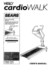
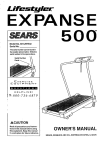
Before reading further, please review the drawing
below and familiarize yourself with the parts that are
labeled.
Pulse Earclip
Console
Handrail
P
_.
Upper Body Arms
Padded Walking Platform
for maximum comfort
FRONT
Foot Rails
Walking Belt
BACK
CircuitBreaker
Rear Rollel
Adjustment Bolts
On/Off 9wltch
Power Cord
RIGHT SIDE
5
ASSEMBLY
Assembly requires two people. Set the treadmill in a cleared area and remove all packing materials. Do not
dispose of the packing materials untll assembly Is completed. THE FOLLOWING TOOLS ARE REQUIRED FOR
ASSEMBLY: The Included 7/32" allen wrench _
and your own adjustable wrench
_
.
1. Pivot the Console (11) until the holes in the Console Crossbar
(6) are aligned with the holes in the Left and Right Uprights (1,
20). Using the 7/32" Allen Wrench (17), loosely thread a 3/8" x 1"
Bolt (5) into each Upright.
6
.
Loosen the Resistance Controls (29) on the Right Upright (20)
and the Left Upright (not shown). Hold the Uprights in the position shown. Hold an Upright Spacer (37) inside the bottom of the
Right Upright. Insert a 3/8" x 3 1/2" Bolt (42), with an Upright
Washer (41), into the lower hole in the Right Upright and the
Upright Spacer. Tighten the Bolt into the side of the Frame (75).
41
Insert another 3/8" x 3 1/2" Bolt (42), with an Upright Washer
(41), into the other hole in the Right Upright (20). Tighten the
Bolt into the side of the Frame (75).
_7
Attach the Left Upright (not shown) in the same manner.
20
41
3. Raise the Left and Right Upper Body Arms (110, 19). Tighten
the Resistance Control (29) on the lower end of each Upper
Body Arm. The use of the Upper Body Arms is explained on
page 7.
See step 1. Using the 7/32" Allen Wrench (17), tighten the 3/8" x
1" Bolt (5) in each Upright (1, 20).
4. Slide the metal Clothes Clip onto the Pulse Earclip in the indicated location. The use of the Pulse Earclip is explained on page 9.
Pulse Earclip
Clothes
Clip
5. Remove the paper backing from the Wrench Clip (95). Press the
Wrench Clip onto the Frame (75) in the indicated location. Press
the Allen Wrench (94) into the Wrench Clip.
5
_,.;÷
75
6
Make sure that all parts are tightened before using the treadmill.
Note: Due to fine particles that may result from normal wear of
the treadmill, it is recommended that a mat be placed underneath the treadmill to protect the floor.
95
94
_42
OPERATION AND ADJUSTMENT
THE LOW-MAINTENANCE
WALKING
BELT
Your treadmill features a low-maintenance walking belt
coated with PERFORMANT LUBE TM, a highperformance lubricant. During the first few hours of
use, it is normal for a small amount of white powder to
appear on the foot rails and the walking platform. The
white powder is high-performance lubricant from the
walking belt. IMPORTANT: Never apply silicone
spray or other substances to the walking belt or
the walking platform. They will deteriorate the
walking belt and cause excessive wear.
A temporary adapter that looks like the adapter illustrated in Drawing 2 may be used to connect this plug
to a 2-pole receptacle as shown in Drawing 2 if a
properly grounded outlet is not available. The
2
Grounded
Outlet Box
Grounding Pin
Grounding
Plug
HOW TO PLUG IN THE POWER CORD
This product must be grounded. If it should malfunction or break down, grounding provides a path of least
resistance for electric current to reduce the risk of electric shock. This product is equipped with a cord having
an equipment-grounding conductor and a grounding
plug. Plug the power cord into an appropriate outlet that is properly installed and grounded in
accordance with all local codes and ordinances.
Lug
-,z_
Metal Screw
temporary adapfer should be used only until a properly
grounded outlet (Drawing 1) can be installed by a qualified electrician. The green colored rigid ear, lug, or the
like extending from the adapter must be connected to
a permanent ground such as a properly grounded outlet box cover. Whenever the adapter is used it must
be held in place by a metal screw.
Some 2-pole receptacle outlet box covers are not
grounded. Contact a qualified electrician to deter,
mine if the outlet box cover is grounded before
using an adapter.
HOW TO USE THE UPPER BODY ARMS
This product is for use on a nominal 120-volt circuit,
and has a grounding plug that looks like the plug illustrated in Drawing 1.
As you exercise on the treadmill, you can either hold
the handrails or use the upper body arms. The upper
body arms are designed to work your arms, shoulders
and back for a total body workout. Hold one upper
body arm with each hand, and move the arms forward
and backward as you walk on the treadmill.
Grounded
Box
The resistance of the
Grounding Plug
upper body
arms can be
I Grounding Pin
Grounded Outlet
adjusted with
the resistance
controls. To
increase the
resistance,
turn the controls clock-
Resistance
wise; to decrease the resistance, rum the controls
counterclockwise.
7
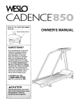
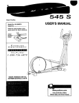
DIAGRAM OF THE CONSOLE
MotivationalFitnessMonitor
I
J
INCUNE
I
PULSE
CALORIES
TIME
SPEED
DISTANCE
Is,-q,-q
I Iss, 1[s 3.selss'.slIs .sl
)I
II
I Iv
.....
The heart of the treadmill is the electronic console.
The console features a SAFEKEY-operated power
switch, electronic speed and incline controls, and six
LED displays to give you continuous exercise feedback. Please read these instructions carefully before
operating the console.
Note: If there is a thin sheet of clear plasticon the face
of the console, peel it off before operating the console.
Jl
I
j
SAFEKEY is in the console when the power cord is
plugged in, a "PO" will appear in the speed display. If
this occurs, remove the SAFEKEY.
Step onto the foot mils of the treadmill. Locate the clip
attached by a cord to the SAFEKEY, and slide the clip
onto the waistband of your clothing. Insert the
SAFEKEY into the power switch.
Note: Some versions of the console can measure distance and speed in either kilometers or miles. To
change the unit of measurement, hold down the STOP
bar while inserting the SAFEKEY in the console. The
SPEED display will show either the letter "M," for
=Metric,"or the letter =E," for =English." Press the
SPEED increase button to select the desired unit of
measurement. Remove the SAFEKEY and then reinsert it.
SPEED CONTROL
HOW TO TURN ON THE POWER
Make sure that the
on/off switch located
near the power cord is in
the "on" position. If the
SAFEKEY Is in the console, remove it.
8
Position
=On"
[_
Plug in the power cord (see HOW TO PLUG IN THE
POWER CORD on page 7). All displays and indicators
on the console will flash three times. Note: If the
When the power is turned on, the walking belt will be
stationary. The speed of the walking belt can be controlled by pressing the SPEED buttons. Each time the
SPEED increase button is pressed, the speed will
increase by 0.1 mile per hour (beginning at 0.5 miles
per hour). Each time the SPEED decrease button is
pressed, the speed will decrease by 0.1 mile per hour.
The buttons can be held down to change the speed
rapidly. The speed can be set at a minimum of 0.5
miles per hour, up to a maximum of 10 miles per hour,
in increments of 0.1 mile per hour.
Press the SPEED increase button until the walking belt
begins to move at slow speed. Hold the handrail, step
carefully onto the walking belt and begin exercising.
Change the speed as desired by pressing the SPEED
buttons. To stop the walking belt, hold down the
SPEED decrease button. The walking belt can be
stopped quickly, if desired, by pressing the STOP bar.
INCLINE CONTROL
TIME DISPLAY--This
display shows the elapsed time.
• SPEED DISPLAY--This display shows the current
speed of the walking belt, in miles per hour.
DISTANCE DISPLAY--The distance display will show
the total distance that you have walked or run, in miles.
To vary the intensity of your exercise, the incline of the
treadmill can be changed by pressing the INCLINE
buttons. Each time one of the buttons is pressed, the
incline will change by 1%. The buttons can be held
down to change the incline rap!dly. The incline can be
set at a minimum of 2%, up to a maximum of 12%.
Note: After the buttons are pressed, it will take a few
Seconds for the treadmill to reach the selected incline
setting.
Note: To reset the displays, remove the SAFEKEY and
then reinsert it into the console.
TURNING OFF THE POWER
To turn off the power, remove the SAFEKEY from the
console. Store the SAFEKEY in a secure location.
INFORMATION
MODE
LED DISPLAY OPERATION
INCLINE DISPLAY--The incline display will show the
selected incline setting of the treadmill.
PULSE DISPLAY--To
use the pulse display,
plug the pulse earclip
into the jack on the console. Attach the earclip
to your left ear lobe and
slide the metal clothes
Pulse Earclip
clip onto your collar.
After a few seconds, your pulse will be shown in the
pulse display. If your pulse is not shown, rub your ear
lobe and reposition the earclip. It may be helpful to
stand still while measuring your pulse.
CALORIES DISPLAY--The calodes display will show
the approximate number of nutritional Calodes that you
have burned. Note: The actual number of Calories you
have burned will vary slightly depending on the speed
and incline of the treadmill.
The console features an information mode to let you
keep track of tdp time and distance, as well as the total
time and distance that the treadmill has been operated. To select the information mode, hold down the
STOP bar while inserting the SAFEKEY into the console.
When the information mode is selected, the time display will show the trip time, up to 9,999 hours. The distance and speed displays together will show the trip
distance, up to 99,999 miles. While the trip time and
distance are displayed, they can be reset to zero by
pressing the INCLINE decrease button.
To view the total time and distance, press the INCLINE
increase button. The time display will show the total
time, up to 9,999 hours. The distance and speed displays together will show the total distance, up to
99,999 miles.
To exit the information mode, remove the SAFEKEY
from the console.
9
TROUBLE-SHOOTING AND STORAGE
Most treadmill problems can be solved by following the simple steps below. Find the symptom that
apples, and follow the steps listed. If further assistance is needed, call our Customer Service Department
toll-free at 1-800-999-3756, Monday through Friday, 6 a.m. until 6 p.m. Mountain Time.
1. SYMPTOM: THE POWER DOES NOT TURN ON
a. Make sure that the power cord is plugged into a properly grounded outlet. (See HOW TO PLUG IN THE
POWER CORD on page 7.) If an extension cord is needed, use only a 14-gauge general-purpose cord of
five feet or less in length.
b. After the power cord has been plugged in, make sure that the SAFEKEY is fully inserted into the console.
Various indicators on the console should light. (See HOW TO TURN ON THE POWER on page 8.)
C.
Check the circuit breaker located on the treadmill near the
power cord. If the switch protrudes as shown, the circuit breaker has tripped. To reset the circuit breaker, wait for five minutes and then press the switch back in.
Reset
Tripped
d. Check the on/off switch located on the treadmill near the
power cord. The switch must be in the "on" position.
"On"
Position
2. SYMPTOM: THE POWER TURNS OFF DURING USE
a. Check the circuit breaker located on the treadmill near the power cord. If the circuit breaker has tripped (see
the drawing above), wait for five minutes and then press the switch back in.
b. Make sure that the power cord is plugged in.
c. Remove the SAFEKEY from the console. Reinsert the SAFEKEY fully into the console. Various indicators on
the console should light.
d. Check to make sure the on/off switch is in the "on" position. (See 1. d. above.)
e. If the treadmill still will not run, please call our Customer Service Department.
3. SYMPTOM: THE PULSE EARCLIP DOES NOT FUNCTION PROPERLY
a. Make sure that the pulse earclip is plugged fully into the jack on the console. Rub your left ear lobe and
reposition the earclip. Attach the clothes clip to your collar.
b. Stand stillwhile measuring your pulse.
• c. The pulse earclip may need to be cleaned. Press the earclip open, and find the two clear circles inside the
earclip. Wipe the two clear circles using a cotton swab moistened with water.
4. SYMPTOM: THE CONSOLE DOES NOT FUNCTION PROPERLY
10
a. If a console malfunction occurs, an error code ("El ," "E2," "E3," etc.) may appear in one of the displays. If an
error code appears, remove the SAFEKEY, wait for ten seconds and then reinsert the 9AFEKEY. If an error
code appears again, call our Customer Service Department. Do not operate the treadmill until the problem is
corrected.
5. SYMPTOM: THE WALKING
a.
BELT SLOWS WHEN WALKED ON
If an extension cord is needed, use only a 14-gauge general-purpose cord of five feet or less in length.
b. If the walking belt is overtightened, treadmill performance may
decrease and the walking belt may be permanently damaged.
Remove the SAFEKEY and UNPLUG THE POWER CORD.
Rear Roller
Adjustment Bolts
Using the 3/16" allen wrench, tum both rear roller adjustment
bolts counterclockwise, 1/4 of a turn. When the walking belt is
properly tightened, you should be able to lift each side of the
walking belt 3 to 4 inches off the walking platform. The center of
the walking belt should just touch the walking platform. Be careful to keep the walking belt centered. Plug in the power cord,
insert the SAFEKEY and rtJn the treadmill for a few minutes.
Repeat until the walking belt is properly tightened.
6. SYMPTOM: THE WALKING BELT IS OFF-CENTER
a.
b.
Co
OR SLIPS WHEN WALKED ON
If the walking belt has shifted to the left, first remove the
SAFEKEY and UNPLUG THE POWER CORD. Using the 3/16"
allen wrench, tum the left rear roller adjustment bolt clockwise,
and the right bolt counterclockwise, 114 of a turn each. Be careful not to overtighten the walking belt. Plug in the power cord,
insertthe SAFEKEY and run the treadmill for a few minutes.
Repeat until the walking belt is centered.
LU
If the walking belt has shifted to the right, first remove the
SAFEKEY and UNPLUG THE POWER CORD. Using the 3/16"
allen wrench, turn the left rear roller adjustment bolt counterclockwise, and the right bolt clockwise, 1/4 of a turn each. Be
careful not to overtighten the walking belt. Plug in the power
cord, insert the SAFEKEY and run the treadmill for a few minutes. Repeat until the walking belt is centered.
If the walking belt slips during use, first remove the SAFEKEY and
UNPLUG THE POWER CORD. Using the3/16" allen wrench, tum
both rear roller adjustment bolts clockwise, 114 of a tum. When the
walking belt is correctly tightened, you should be able to lift each
side of the walking belt 3 to 4 inches off the walking platform. The
center of the walking belt shouldjust touch the walking platform. Be
careful to keep the walking belt centered. Plug in the power cord,
insert the SAFEKEY and run the treadmill for a few minutes.
Repeat until the walking belt is properly tightened.
7. SYMPTOM: THE NUMBERS IN THE SPEED AND DISTANCE
DISPLAYS SEEM VERY HIGH OR LOW
a. Some versions of the console can measure distance and speed in either kilometers or miles. To change the
unit of measurement, hold down the STOP button whileinserting the SAFEKEY in the console. The SPEED
display will show either the letter "M," for "Metric," or the letter "E,, for "English." Press the SPEED Increase
button to select the desired unit of measurement. Remove the SAFEKEY from the console.
STORAGE
Unplug the power cord when the treadmill is not in use.
Remove the bolts, washers and spacer from the lower end of each
upright. Loosen the resistance control on each upright. Carefully lay
the console and upper body arms on the treadmill. Hand tighten the
bolts with the washers and spacers into the treadmill frame. Cover the
treadmill during extended periods of storage.
Remove
11
CONDITIONING GUIDELINES
The following guidelines will help you to plan your
exercise program. Remember that proper nutrition
and adequate rest are essential for successful results.
During the first few months of your exercise program,
keep your heart rate near the low end of your training
zone as you exercise. After a few months of regular
exercise, your heart rate can be increased gradually
until it is near the middle of your training zone as you
exercise.
You can measure your heart rate using the pulse
mode of the console. Exercise for at least four minutes, and then measure your heart rate immediately.
If your heart rate is too high, decrease the intensity of
your exercise. If your heart rate is too low;'increase
the intensity of your exercise.
EXERCISE INTENSITY
To maximize the benefits of exercising, it is important
to exercise with the proper intensity. The proper intensity level can be found by using your heart rate as a
guide. For effective aerobic exercise, your heart rate
should be maintained at a level between 70% and
85% of your maximum heart rate as you exercise.
This is known as your training zone. You can find your
training zone in the table below. Training zones are
listed according to age and physical condition.
WORKOUT GUIDELINES
Training Zone (Beats/Min.)
12
Age
Unconditioned
Conditioned
20
138-167
133-162
25
136-166
132-160
30
135-164
130-158
35
134-162
129-156
40
132-161
127-155
45
131-159
125-153
50
129-156
124-150
55
127-155
122-149
60
126-153
121-147
65
125-151
119-145
70
123-150
118-144
75
122-147
117-142
80
120-146
115-140
85
118-144
114-139
Each workout should consist of three basic pads: a
warm-up, 20 to 30 minutes of training zone exercise,
and a cool-down.
Warming up prepares the body for exercise by
increasing circulation, delivering more oxygen to the
muscles and raising the body temperature. Begin
each workout with 5 to 10 minutes of stretching and
light exercise to warm up. Then, increase the intensity
of your exercise to raise your heart rate to your training zone for 20 to 30 minutes. Breathe regularly and
deeply as you exercise--never hold your breath.
Finish each workout with 5 to 10 minutes of stretching
to cool down. This will increase the flexibility of your
muscles as well as help to decrease soreness and
other post-exercise problems.
To maintain or improve your condition, plan three
workouts each week, with at least one day of rest
between workouts. After a few months of regular exercise, you may complete up to five workouts each
week, if desired. The key to success is to make
exercise a regular and enjoyable part of your everyday life.
SUGGESTED
STRETCHES
The following stretches can provide a good warm-up or cool-down. Correct form for each stretch is shown in the
drawings below. Move slowly as you stretch---never bounce.
TOE TOUCH STRETCH
Stand with your knees bent slightly and slowly bend forward
from your hips. Allow your back and shoulders to relax as you
reach down toward your toes as far as possible. Hold for 15
counts, then relax. Repeat 3 times.
Stretches: Hamstrings, back of knees and back.
HAMSTRING STRETCH
Sit with one leg extended. Bring the sole of the opposite foot
toward you and rest it against the inner thigh of your extended
leg. Reach toward your toes as far as possible. Hold for 15
counts, then relax. Repeat 3 times for both legs.
Stretches: Hamstrings, lower back and groin.
CALF/ACHILLES STRETCH
With one leg in front of the other, reach forward and place your
hands against a wall. Keep your back leg straight and your
back foot fiat on the floor. Bend your front leg, lean forward and
move your hips toward the wall. Hold for 15 counts, then relax.
Repeat 3 times for both legs. To cause further stretching of the
achilles tendons, bend your back leg as well.
Stretches: Calves, achilles tendons and ankles.
QUADRICEPS STRETCH
With one hand against a wall for balance, reach back and grasp
one foot with your other hand. Bdng your heel as close to your
buttocks as possible. Hold for 15 counts, then relax. Repeat 3
times for both legs.
Stretches: Quadriceps and hip muscles.
INNER THIGH STRETCH
Sit with the soles of your feet together and your knees outward.
Pull your feet toward your groin area as far as possible. Hold
for 15 Counts, then relax. Repeat 3 times.
Stretches: Quadricepsand hipmuscles.
13
PART LIST--Model No. PFTL20250
Key
No.
1
2
3
4
5
6
7
8
9
10
11
12
13
14
15
16
• 17
18
19
20
21
22
23
24
25
26
27
28
29
30
31
32
33
34
35
36
•37
38
39
40
41
42
43
44
45
•46
47
45
49
50
51
52
53
54
57
58
59 .
60
14
Qty.
1
2
2
2
2
1
6
6
1
1
1
1
2
1
1
1
1
1
1
1
3
1
1
4
2
1
2
1
2
1
8
1
1
1
1
2
2
1
15
2
4
4
1
1
6
1
1
1
1
1
1
2
2
1
1
1
2
1
3
2
Description
Left Upright/Handrail
Upper Body Arm Foam
Rear Leg Endcap
Handrail Endcap
3/8" x 1" Bolt
Console Crossbar
Cage Nut
Console Screw
Wire Cover
Upright Wire Hamess
Console
SAFEKEY_/Clip
Motor Nut
Pulse Earclip/Clothes Clip
Speed Disk
Optic Switch Bracket
7/32" Allen Wrench
Crossbar Cable Loom
Right Upper Body Arm
Right Upright/Handrail
Belt Guide Screw
Right Resistance Cover
Resistance Bolt
Thrust Washer
Thrust Beating
Left Leather/Metal Resistance Plate
Resistance Plate
Switch Star Washer
Resistance Control
Front Roller Adjustment Bolt
Roller Adjustment Washer
Front Right Endcap
Front Left Endcap
Front Roller/Pulley
Uptight Cable Loom
Upper Body Arm Cover
Uptight Spacer
20 =Wire Hamess
Safety Cover Screw
Plastic Spacer
Updght Washer
3/8" x 3 1/2" Bolt
14" Power Board/Controller Wire
Belt Guide
Small Screw
Electronics Bracket
6" Cable Loom
Grommet
Circuit Breaker
On/Off Switch
Power Cord
Wheel Bolt
Front Wheel
Power Cord Bracket
Left Upper Body Arm
Controller
Wheel Nut
Safety Cover Bracket
Incline Leg Bolt/Motor Tension Bolt
Incline Leg Washer
R895A
Key
No.
Qty.
61
62
63
64
65
66
67
68
69
70
71
72
73
74
75
76
77
78
79
80
81
82
83
84
85
86
87
88
89
90
91
92
93
94
95
96
97
98
99
100
101
102
103
104
105
106
107
108
109
#
#
#
#
#
#
#
#
#
#
5
1
1
4
2
2
1
1
1
1
1
1
8
1
1
1
2
2
2
1
2
1
1
2
4
1
1
1
2
1
2
8
1
1
1
1
1
2
1
1
1
2
1
1
1
1
1
1
1
1
1
1
1
1
1
1
1
1
1
Note: "#" indicates a non-illustrated part. Specifications are subject
Description
Incline Leg Nut/Motor Tension Nut
Incline Leg
Power Board
Plastic Stand-Off
Cover Washer
Large Tension Spacer
Front Safety Cover
Right Foot Rail
Rear Safety Cover
Walking Belt
Star Washer
Motor Belt
Platform Screw
Walking Platform
Frame
Optic Switch Bracket Nut
Optic Switch
Small Bolt
Small Nut
Incline Optic Disk
Incline Motor Bolt
Incline Motor
Incline Motor Spacer
Optic Switch Wire Hamess
Endcap Screw
Incline Stop Bracket
Motor
Right Rear Endcap
Rear Roller Adjust Bolt
Cable Tie Wrap
4" Cable Tie
8" Cable Tie
Tie Block
3/16" Allen Wrench
Wrench Clip
Rear Roller
Left Rear Endcap
Foot Rail Bracket
Left Foot Rail
Choke Bracket
Choke
Motor Bolt
Right Leather/Metal Resistance Plate
Motor Swivel Bolt
Motor Tension Washer
Motor Tension Nut
Motor Mount Bracket
Pulley/Flywheel/Fan
Left Resistance Cover
9" Black Wire, Male/Female
8" Black Wire, 2 Female
4" Black Wire, 2 Female
8" White Wire, Male/Female
8" White Wire, 2 Female
14" Blue Wire, Male/Female
8" Blue Wire, 2 Female
8" Green Ground Wire
8" Red Wire, Male/Female
Owner's Manual
to change without notice.
"
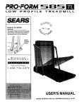
EXPLODED DRAWING--Model
No. PFTL20250
R89SA
12
11
7
111
9
7
112
29
10
24
8
87
15
42
8
41
16
77
79
76
23
78
27
25
32
31
101
29
70
/
74
69
41
67
68
21
21
64
75
61
89
21
80'
61
81
61
51
83
15
ORDERING REPLACEMENT PARTS
To order replacement parts, call our Customer Service Department toll-free at 1-800-999-3756, Monday through
Friday, 6 a.m. until 6 p.m. Mountain Time (excluding holidays). When ordering parts, please be prepared to give
the following information:
• The MODEL NUMBER of the product (PFTL20250).
• The NAME of the product (PROFORM ®CROSSWALK ®EXCEL TM treadmill).
• The SERIAL NUMBER of the product (see the front cover of this manual).
* The KEY NUMBER of the part(s) (see page 14 of this manual).
.
The DESCRIPTION
of the part(s) (see page 14 of this manual),
If possible, place the treadmill near your telephone for easy reference when calling.
Part No. 126128 R895A Printed in USA
© 1995 ICON Health & Fitness, Inc.