1
LS
ehte
0-8 mph • 2.0 hp • direct pulse interface • fat burn guide
SEARS"
Model No. 831.297540
Serial No.
The serial number can be found in the
location shown below. Write the serial
number in the space above.
Serial Number Decal
CAUTION!:
Read all safety precautions and
instructions in this manual
before using thls equipment.
Keep this manual in a safe place
for future reference.
OWNER'S
MANUAL
FULL 90 DAY WARRANTY
For 90 days from the date of purchase, when prcper assembly and maintenance procedures detailed in
the Owner's Manual are followed, SEARS will, free of charge, repair or replace and install a replacement
part for any defective pad, when this treadmill is used in a normal manner.
This warranty does not apply when this treadmill is used for commercial or rental purposes.
SERVICE IS AVAILABLE SIMPLY BY'CONTACTING YOUR NEAREST SEARS SERVICE CENTEPJDEPARTMENT IN THE UNITED STATES. d
This warranty gives you specific legal rights, and you may also have other rightswhich vary from state
to state.
SEARS, ROEBUCK AND CO., DI_PT. 817WA_
HOFFMAN ESTATES, IL 6(_179
2
LS elite
O
0-8 mph ° 2.0 hp • direct pulse interface • fat burn guide
TABLE OF CONTENTS
IMPORTANT SAFETY PRECAUTIONS .........................................................
BEFORE YOU BEGIN .......................................................................
ASSEMBLY ...............................................................................
HOW TO USE THE PULSE SENSOR ..........................................................
OPERATION AND ADJUSTMENT
.......................
: .....................................
TROUBLE-SHOOTING
AND STORAGE ........................................................
.CONDITIONING GUIDELINES ...............................................................
PART LIST ...............................................................................
EXPLODED DRAWING .....................................................................
ORDERING REPLACEMENT PARTS .................................................
_WAR
4
5
6
8
9
14
16
18
19
Back Cover
NI N G:
Before beginning this or any exercise program, consult your physician.
Thls is especially important for persons over the age of 35 or persons with pre-existing health problems.
Read all instructions before using. SEARS assumes no responsibility for personal injury or property
damage sustained by or throuqh the use of this product.
3
IMPORTANT
SAFETY PRECAUTIONS
A WARNING:
To reduce the risk Of burns, fire, electric shock or injury to persons, read the following important safety precautions and information before operating the treadmill.
1. Position the treadmill on a level surface, with at least 8 feet of clearance behind the treadmill. Do not
place the treadmill near water, outdoors or on any surface that blocks an air opening. Do not operate
where aerosol products are used or where oxygen is being administered.
2. When connecting the power cord (see PLUGGING IN THE POWER CORD on page 9), plug the power
cord directly into a grounded circuit capable of carrying 12 or more amps. No other appliance should
be on the same circuit. Keep the power cord away from heated surfaces. If an extension cord is needed, use only a 14-gauge general-purpose cord of five feet or less in length with a three-wire conductor.
3. Never move the walking belt while the power Is turned off. Do not operate the treadmill if the power
cord ol' plug is damaged, or if the treadmill is not working properly. (See BEFORE YOU BEGIN on
page 5if the treadmill is not working properly.)
4. Wear appropriate exercise clothing when using the treadmill; do not wear loose clothing that could
become caught in the treadmill. Always wear ath/eUc shoes; never use the treadmill with bare feet,
wearing on/), stockings or in sandals. Athletic support clothes are recommended for both men and
women.
5. The pulse sensor Is not a medical device. Various factors, including the user's movement while exercising, may affect the accuracy of heart rate readings. The sensor is intended only as an exercise aid
In determining heart rate trends in general.
6. Never start the treadmill while you are standing on the walking belt. Always hold the handrail when
exercising on the treadmill.
7. Never allow more tha_none person on the treadmill at a time. The treadmill should not be used by persons weighing more than 250 pounds.
8. Keep small children away from the treadmill at all times. Never leave the treadmill unattended while it
' Is running. Always turn the power off when the treadmill is not in use.
9. Never drop or insert any object into any opening.
10. To reduce the possibility of overheating, do not operate the treadmill continuously for longer than 1
hour.
11. The treadmill is capable of high speeds. Adjust the speed slowly to avoid sudden jumps in speed.
12. Use the treadmill only as described in this manual.
13. Always unplug the power cord before performing the maintenance and adjustment procedures
described in this manual. Never remove the safety cover unless instructed to do so by an authorized
service representative. Servicing other than the procedures in this manual should be performed by an
authorized service representative only.
SAVE THESE INSTRUCTIONS
BEFORE
YOU
BEGIN
Thank you for selecting the SEARS LS ELITE 780 treadmill. The LS ELITE 780 treadmill blends advanced technology with innovative design to let you enjoy an excellent form of cardiovascular exercise in the convenience
and privacy of your home.
For your safety and benefit, read this manual carefully before using the treadmill. If you have additional
questions, please call our Customer Service Department toll-free at 1-800-999-3756, Monday through Friday, 6
a.m. until 6 p.m. Mountain Time (excluding holidays). To help us assist you, please note the product model number and serial number before calling. The model number of the treadmill is 831.297540. The serial number can be
found on a decal attached to the treadmill (see the front cover of this manual for the location).
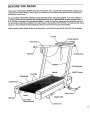
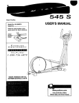
Before reading further, please review the drawing below and familiarize yourself with the parts that are labeled.
Console
Handrail
Console Knob
Uprights
FRONT
ON/OFF Switch
Foot Rails
Walking Belt
Cushion
\
Power Cord
BACK
RIGHT SIDE
Bet .
Rear Roller
Adjustment Bolt
Cushion Foot
5
ASSEMBLY
Assembly requires the assistance of a second person. Set the treadmill in a cleared area and remove all
packing materials. Do not dispose of the packing materials until assembl_is completed. THE FOLLOWING
TOOLS ARE REQUIRED FOR ASSEMBLY: An adjustable wrench _
(not Included).
.
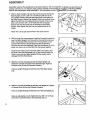
Find the Right Upright (15) (see the inset drawing to identify the
Right Upright). Insert a 3/8" x 3 1/2" Bolt (27) with one of the
four Upright Washers (26) into the higher hole in the bottom of
the Right Upright. Slide a Fiat Washer (100) onto the Bolt. Hand
tighten the Bolt into the indicated hole in the side of the Frame
(50). Insert another 3/8" x 3 1/2" Bolt (27) with an Upright
Washer (26) into the lower hole in the bottom of the Right
Upright. Hand tighten the Bolt into the indicated hole in the
Frame.
5O
27
15
.
With the help of a second person, hold the Console Crossbar (6)
near the Right Upright (15). Connect the Console Wire Harness
(10) to the Upright Wire Harness (12). The small latch on the
Console Wire Harness should snap onto the Upright Wire
Harness (see the inset drawing). If the Wire Harnesses do not fit
easily, turn them; do not force the Wire Harnesses together.
2
6
Adjust the 24" Cable Lcorn (11) and 6" Cable Loom (30) so that
the ends of the Wire Harnesses (10, 12) are covered. Insert the
Cable Looms into the I_ight Upright (15). Be careful not to
damage the Wire Harn;_sses.
3. Slide the Console Crossbar (6) into the Right Upright (15).
Rotate the Console Crossbar to the desired angle. Tighten a
Console Knob (3) into the Console Crossbar.
11 12
3O
3
4
15
S
Push an Upright Endcap (4) into the end of the Right Upright
(15).
4. Slide the Console Crossbar (6) into the Left Upright (2). Tighten
a Console Knob (3) into the Console Crossbar.
27
26
Attach the Left Upright (not shown) in the same manner.
4
4
3
Push an Upright Endcap (4) into the end of the Left Upright (2).
2
Using an adjustable wrench, tighten the four 3/8" x 3 1/2" Bolts
(27) used in assembly step 1 (see assembly step 1).
6
6
3
5. Plug the lower end of the Upright Wire Harness (12) into the 20"
Wire Harness (45). The small latch on the Upright Wire
• Harness should snap onto the 20" Wire Harness (see the upper
inset drawing). If the Wire Harnesses do not fit easily, turn
them; do not force the Wire Harnesses together.
Adjust the 6" Cable Loom (30) so that the Cable Loom is inserted into the Right Upright (15) and the Rear Safety Cover (52)
(see the lower inset drawing). Be careful not to damage the
Wire Harnesses.
12
52
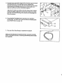
6. Press the Belt Tool (86) into the opening in the Left Rear
Endcap (82). The Belt Tool is used to center the Walking Belt
(see SYMPTOM 6 on page 14).
86
7. The use of the Pulse Sensor is explained on page 8.
7
Make sure that all parts are tightened I_efore using the treadmill.
Note: To protect the floor, a covering should be placed under
the treadmill.
7
HOW TO USE THE PULSE SENSOR
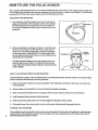
"the LS ELITE 780 treadmill features an innovative headband-style pulse sensor. The rubber-armored pulse sensor and lightweight headband are specially designed for greater accuracy, comfort and durability• To get the best
performance from the pulse sensor, please read the following instructions•
ADJUSTING THE HEADBAND
1• The headband should fit snugly around your head, without
being uncomfortable. If the headband needs to be adjusted,
slip the headband off the adjustment tab on the pulse sensor. Insert the adjustment tab through a different hole in the
headband.
.
ustment
Rub your forehead to stimulate circulation. Put on the headband as shown. Make sure that the sensor window is centered on your forehead. If necessary, adjust the headband
as described above. IMPORTANT: To avoid static build-
Sensor
up, the pulse sensor should be worn only while you are
standing on the treadmill•
Find the clip that isattached to the pulse sensor wire, and
•
%
•
.
•
•
•
shde the cbp onto your collar. The chp w=llmtmm ze movement of the wire during exercise, helping to ensure accurate
pulse readings.
Cli
/
HOW TO oBTAIN ACCURATE PULSE READINGS
The instructions on pages 11 and 12 describe how to use the pulse sensor with the console. To ensure the best
results, remember the following important guidelines:
1. Make sure that the headband is properly adjusted• If the headband is too tight or too loose, your pulse may
not be detected.
2. Before putting on the headband, rub your forehead to stimulate circulation.
3. Make sure that the headband is worn properly, with the sensor window centered on your forehead.
4. Avoid excessive head movement during exercise.
5,
Make sure that the pulse sensor wire is fully plugged intothe jackon the console. -
6-" Periodically clean the sensorwindow using a cotton swab moistened with denatured alcohol.
WASHING THE HEADBAND
8
The headband can be removed from the pulse sensor and washed• Hand wash the headband in mild detergent•
Gently wring out the headband and let it dry. The pulse sensor can be wiped clean with a damp cloth; do not
Immerse the pulse sensor In water.
OPERATION AND ADJUSTMENT
PLUGGING IN THE POWER CORD
This product must be grounded. If it should malfunction or break down, grounding provides a path of least
resistance for electric current to reduce the risk of electric shock.
This product is equipped with a cord having an equipment-grounding conductor and a grounding plug. Plug the
power cord into an appropriate outlet that is properly installed and grounded in accordance with all local
codes and ordinances.
DAN GER:
Improper connection of the equipment-grounding conductor can result in a risk of elec-
tric shock. Check with a qualified electrician or serviceman if you are in doubt as to whether the product is property grounded. Do not modify the plug provided with the product--if it will not fit the outlet, have a proper outlet
installed by a qualified electrician.
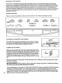
This product is for use on a nominal 120-volt circuit, and has a grounding plug that looks like the plug illustrated in
Drawing 1.
A temporary adapter that looks like the adapter illustrated in Drawing 2 may be used to connect this plug to a 2pole receptacle as shown in Drawing 2 if a properly grounded outlet is not available. The temporary adapter
should be used only until a propedy grounded outlet (Drawing 1) can be installed by a qualified electrician. The
green colored rigid ear, lug, or the like extending from the adapter must be connected to a permanent ground
such as a propedy grounded outlet box cover. Whenever the adapter is used it must be held in place by a metal
screw.
Some 2-pole receptacle outlet box covers are not grounded. Contact a qualified electrician to determine if
_theOutlet box cover is grounded before using an adapter.
kI
• Grounded Outlet Box
2
Grounding Plug
Grounding Pin
Grounding Pin
Grounded Outlet
MAINTENANCE-FREE
WALKING BELT
Your treadmill features a maintenance-free walking bolt. IMPORTANT: Never apply silicone spray or other
substances to the walking belt or the walking platform, They will deteriorate the walking belt and cause
excessive
wear.
CUSHION LEVEL ADJUSTMENT
For a softer cushion level as you exemise, turn the cushion knob
ctockwise. For a firmer cushion level, turn the knob counterclockwise. Note: The faster you run on the treadmill, the firmer the
cushion level should be. If the cushion level is too soft, the treadmill will bounce excessively.
Cushion Knob
9
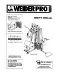
DIAGRAM OF THE CONSOLE
The heart of the treadmill is the state-of-the-art interactive console. The console offers electronic speed and
incline control, six independent LED displays, and a Fitness Test that measures your fitness level. In addition, a
unique Fat Calorie Monitor is built into the console. During exercise, your body burns either fat calories or carbohydrate calories, depending on the intensity of your exercise. If your goal is to burn fat, it is essential that you
exercise at the proper intensity level. The Fat Calorie Monitor will constantly monitor your workout, and show you
when your intensity level is too low, too high or perfect for burning fat. Carefully read these instructions before
operating the console.
CONSOLE DIAGRAM
If there is a sheet of clear plasticon the face of the console, remove it before operating the console.
o
_OO_OO_
o
]
J
k
ADJUSTING THE ANGLE OF THE CONSOLE
Console
The angle of the consdie can be adjusted for easy viewing. To adjust
the console, first loosen the knob on each side of the console. Rotate
the console to the desired angle and retighten the knobs.
TURNING ON THE POWER
•
Make sure that the safety key is not in the console. Make sure that the
on/off switch located near the power cord is in the =on"position. Plug in
the power cord (see PLUGGING IN THE POWER CORD on page 9).
All displays and indicators will flash three times. Note: If the safety key
is in the console when the power cord is plugged in, the letters "PO"
will flash in the SPEED display. If this occurs, simply remove the safety
Position
key.
Step onto the foot rails of the treadmill. Find the clip attached to the safety key, and slide the clip onto the waistband of your clothing.
WARNING:
Always
stand
on the foot rails when turning on the power or starting the walking
>ell Always wear the cllp while operating the treadmill.
10
nsert the safety key into the console. The "NO PULSE DETECTED" indicator, the MANUAL CONTROL indicator,
_nd the six LED displays will light. The PULSE display will flash the current age setting three times, and the
,3ALORIES display will flash the current weight setting three times. (if age and weight settings have never been
entered into the console, the PULSE display will flash the letters "AGE" three times, and the CALORIES display
will flash the letters "LBS" (pounds) three times.
ENTERING
YOURAGEANDWEIGHT
For the console to measure calories accurately, and for the Fat Calorie Monitor and the Fitness Test to function
properly, your age and weight must be entered into the console. To enter your age, press one of the AGE SET
buttons. The current age setting will be shown in the PULSE display. Each time one of the AGE SET buttons is
pressed, the age setting will change by 1 year. If the buttons are held down, the age setting will change in increments of 5 years. After you have entered your age, press one of the WEIGHT SET buttons. The current weight
setting will be shown in the CALORIES display. Each time one of the WEIGHT SET buttons is pressed, the
weight setting will change by I pound. If the buttons are held down, the weight setting will change in increments
of 5 pounds.
Once you have entered your age and weight, the numbers will be retained in the console's memory, even if the
power cord is unplugged. The numbers can be changed, if desired, by pressing the AGE SET or WEIGHT SET
buttons.
CONTROLLING
THE SPEED
When the power is turned on, the console will be in the MANUAL CONTROL mode, and the walking belt will be
stationary. The speed of the walking belt is controlled by pressing the SPEED buttons. Each'time the INCREASE
SPEED button is pressed, the speed will increase by 0.1 mile per hour, beginning at 0.5 miles per hour. Each
time the DECREASE SPEED button is pressed, the speed will decrease by 0.1 mile per hour. The buttons can be
held down to change the speed rapidly. The speed range of the walking belt is 0.5 miles per hour to 10 miles per
hour.
WAR N ING: A.erthe SPEED buttons
are pressed, it will take a moment for the walking belt to
reach the selected speed setting. Adjust the speed gradually
the treadmill.
until you are familiar with the operation of
Press the INCREASE SPEED button until the walking belt begins to move at slow speed. Hold the handrails, step
carefully onto the walking belt, and begin exemising. Change the speed as desired by pressing the SPEED buttons. To stop the walking belt, hold down the DECREASE SPEED button, or press the STOP button.
CONTROLLING
THE INCLINE
To vary the intensity of your exercise, the incline of the treadmill can be changed by pressing the INCLINE buttons. Each time one of the buttons is pressed, the incline will change by 0.5%. The buttons can be held down to
change the incline rapidly. The incline range of the treadmill is 1% to 12%. Note: Because the INCLINE display
has two digits, the display will show 10% when the incline is set at either 10% or 10.5%, and 11% when the
incline is set at 11% or 11.5%.
Note: After the INCLINE buttons are pressed, it will take a few seconds for the treadmill to reach the
selected incline setting.
LED DISPLAY OPERATION
PULSE DISPLAY--To measure your pulse, first put on the pulse sensor (see HOW TO USE THE PULSE SENSOR on page 8). Plug the pulse sensor wire fully into the jack on the front of the console. After a few seconds,
the heart indicator will gash each time your heart beats, the "NO PULSE DETECTED" indicator will darken, and
your pulse will be shown. If your pulse is not shown, see HOW TO OBTAIN ACCURATE PULSE READINGS on
page 8.
CALORIES DISPLAY--For the console to measure calories accurately, your age and weight must be entered
into the console. If your age and weight have not been entered, see ENTERING YOUR AGE AND WEIGHT
above. The CALORIES display will show the total number of calodes that you have burned. To find the number of
fat calories that you have burned, press the TOTAL FAT CALORIES button. The number of fat calories that you
have burned will be shown in the CALORIES display for three seconds.
INCLINE DISPLAY--The
incline display will show the incline level that has been selected.
11
SPEED DISPLAY--The
speed display will show the speed setting that has been selected.
TIME DISPLAY--The time display will show the total tir_e that the walking belt has been moving. Note: If the
Fitness Test is selected, the display will be reset to zero. The display will be reset again when the Fitness Test is
completed.
DISTANCE DISPLAY--The distance display will show the total distance that you have walked or run, in miles.
Note: If the Fitness Test is selected, the display will be reset to zero. The display will be reset again when the
Fitness Test is completed.
FAT CALORIE MONITOR
The Fat Calorie Monitor is designed to help you maintain the proper workout intensity level for burning fat. For the
Fat Calorie Monitor to operate properly, your age and weight must be entered into the console. If your age and
weight.have not been entered, see ENTERING YOUR AGE AND WEIGHT on page 11. In addition, the pulse
sensor must be used (see HOW TO USE THE PULSE SENSOR on page 8).
When the Fat Calorie Monitor is activated, one of the five indicators in the center of the console will light. The two
red indicators on the left indicate that your intensity level is too low for burning fat effectively. The two red indicators on the right indicate that your intensity level is too high for burning fat effectively. When your intensity level is
perfect for burning fat, the green indicator in the center will light. As you exercise, simply adjust the speed of the
walking belt and the incline of the treadmill so that the green indicator remains lit.
FITNESS TEST
The Fitness Test is designed to measure your general fitness level. For the best results, the Fitness Test should
be taken at a time of day when your energy level is high. The Fitness Test should not be taken after you have
. already exercised during the day. To select the Fitness Test, press the FITNESS TEST button. The PULSE display will flash the current age setting three t rues, and the CALORIES display will flash the current weight setting
three times. For the Fitness Test to operate proper y, your age and weight must be entered into the console. If
your age and weight have'not been entered, see ENTERING YOUR AGE AND WEIGHT on page 11. In addition,
the pulse sensor must be used. If your pulse is not detected, the letters "PLS" will flash in the PULSE display.
See HOW TO USE THE PULSE SENSOR on page 8. The INCLINE display will show that the treadmill is at an
incline level of 2%. The CALORIES, SPEED, TIME and DISTANCE displays will reset to zero. Note: While the
console is in the Fitness Test mode, the SPEED buttons, INCLINE buttons, and Fat Calorie Monitor will not function.
The Fitness Test consists of seven 3-minute segments. The console will automatically control the incline .ofthe
treadmill and the speed of the walking belt during the Fitness Test. During the first segment, the incline will be at
2%, and the speed will be 1.5 miles per hour;,at the beginning of the second segment, the incline will increase to
3%, and the speed will increase to 2.5 miles per hour; at the beginning of the third segment, the speed will
increase to 3.3 miles per hour; at the beginning of the fourth segment, the incline will increase to 6%; at the
beginning of the fifth segment, the incline will increase to 9%; at the beginning of the sixth segment, the incline
will increase to 12%; at the beginning of the seventh segment, the speed will increase to 4 miles per hour.
To start the Fitness Test, stand on the foot rails of the treadmill and press the FITNESS TEST button again. Tl_e
first segment of the Fitness Test will begin, and the walking belt will begin to move at 1.5 miles per hour. Step
onto the walking belt and begin exemising. After three minutes, the second segment will begin. After another
three minutes, the third segment will begin. The Fitness Test will continue in this manner until your heart rate
reaches 70=/=of your maximum heart rate, and the current segment is completed. The walking belt will then slow
to a stop, and your fitness level will be shown in the TIME display. There are ten fitness levels--fitness level 1 (FL
1) is the lowest, and fitness level 10 (FL10) is the highest. Remember, the Fitness Test is intended only to indicate your general fitness level, and to show your progress over a period of time.
If your pulse is not detected during the last thirty seconds of any segment, the walking belt will slow to a stop and
the TIME display will show "FL 0," indicating that an error has occurred. If you wish to stop the walking belt while
the Fitness Test is in progress, press the STOP button. The console will then be in the MANUAL CONTROL
mode.
12
TURNINGOFFTHEPOWER
To turn off the power, remove the safety key from the console. All indicators and LED displays will darken. Store
the safety key in a secure location.
INFORMATION
MODE
The console features an information mode that keeps track of trip time and distance, as well as the total time and
distance that the treadmill has been operated. To select the information mode, hold down the STOP button while
inserting the safety key into the console.
The SPEED display will show the letter "T,=indicating that trip time and distance are shown. The trip time will be
shown in the TIME display. The trip distance will be shown in the DISTANCE display. The trip time and distance
can be reset to zero, if desired, by pressing the WEIGHT SET DECREASE button.
To view total time and distance, press the FITNESS TEST button. The letter "£' in the SPEED display will darken.
The total time will be shown in the TIME display, up to 9,999 hours. The total distance will be shown in the DISTANCE display, up to 999-miles (if the total distance exceeds 999 miles, the display will begin again at zero). The
total time and distance cannot be reset to zero.
To exit the information mode, remove the safety key.
13
TROUBLE-SHOOTING
AND STORAGE
Most treadmill problems can be solved by following the simple steps below. Find the symptom that applies,
and follow the steps listed. If further assistance is needed, call our Customer Service Department toll-free at 1800-999-3756, Monday through Friday, 6 a.m. until 6 p.m. Mountain Time.
1. SYMPTOM: THE POWER DOES NOT TURN ON
a. Make sure that the power cord is plugged into a properly grounded outlet. (See OPERATION AND ADJUSTMENT on page 9.) If an extension cord is needed, use only a 14-gauge general-purpose cord of five feet or
less in length.
b. After the power cord has been plugged in, make sure that the safety key is fully inserted into the console.
Various indicators on the console should light. (See OPERATION AND ADJUSTMENT on page 9.)
c. Check the circuit breaker located on the treadmill near the
power cord. If the switch protrudes as shown, the circuit
breaker has tripped. To reset the circuit breaker, wait for five
minutes and then press the switch back in.
Tripped
d. Check the On/Off switch located at the front of the treadmill
near the power cord. The switch must be in the On position.
_
Reset
On
Position
2. SYMPTOM: THE POWER TURNS OFF DURING USE
a. Check the circuit breaker located on the treadmill near the power cord. If the circuit breaker has tripped (see
the drawing above.), wait for five minutes and then press the switch back in.
b. Make sure that the power cord is plugged in.
c. Remove the safety key from the console. Reinsert the safety key fully into the console. Various indicators on
the console should light.
d. Check to make sure the On/Off switch is in the On position. (See 1. d. above.)
e. If the treadmill still will not run, please call our Customer Service Department.
o
SYMPTOM: THE PULSE SENSOR DOES NOT FUNCTION PROPERLY
a. See HOW TO USE THE PULSE SENSOR on page 8.
4. SYMPTOM: THE CONSOLE DOES NOT FUNCTION PROPERLY
a. If a console malfunction occurs, an error code ("El," =E2," "E3," etc.) may appear on the display. If an error code
appears, remove the safety key, wait for ten seconds and then reinsert the safety key. If an error code appears
again, call our Customer Service Department. Do not operate the treadmill until the problem is corrected.
5. SYMPTOM: THE WALKING BELT SLOWS WHEN WALKED ON
a. If an exlensioncord is needed, use only a 14-gauge general-purpose cord of five feet or less in length.
b. If the walking belt still slows when walked on, please call our Customer Service Department.
6. SYMPTOM: THE WALKING BELT IS OFF-CENTER WREN WALKED ON
a. If the walking belt has shifted to the left, first remove the safety
key and UNPLUG THE POWER CORD. Using the belt tool,
turn the rear roller adjustment bolt clockwise 1/4 of a turn. Plug
in the power cord, insert the safety key and run the treadmill
for a few minutes. Repeat until the walking belt is centered.
14
a
=_"
I=
_
Belt Tool
keyand UNPLUG THE POWER CORD. Using the belt tool, turn
the rear roller adjustment bolt counterclockwise 1/4 of a turn.
Plug in the powercord,insertthe safety key and runthetreadmillfor a few minutes.Repeat untilthewalkingbelt is centered.
_'Belt
Tool
U
STORAGE
o
Unplug the power cord when the treadmill is not in use.
Remove one bolt and washer from the lower ends of the left
and right uprights. Loosen the other bolt on each side.
Carefully lay the console on the treadmill. Keep the bolts and
washers in a secure location.
It is recommended that the treadmill be covered during extended periods of storage.
15
CONDITIONING
GUIDELINES
• The following guidelines will help you to plan your exercise program. Remember that proper nutrition and adequate rest are essential for successful results.
RNING: Before
beginning this or any exercise prog ram, consult your physician. This is
especially Important for individuals over the age of 35 or individuals with pre-existing health problems.
EXERCISE INTENSITY
To maximize the benefits of exercising, it is important to exercise with the proper intensity. The proper intensity
level can be found by using your heart rate as a guide. For effective aerobic exercise, your heart rate should be
maintained at a level between 70% and 85% of your maximum heart rate as you exercise. This is known as your
training zone. You can find your training zone in the table below.
. o-
"
AGE
UNCONDITIONED
TRAINING ZONE
(BEATS/MIN)
CONDITIONED
TRAINING ZONE
(BEATS/MIN)
AGE
!UNCONDITIONED
TRAINING ZONE
(BEATS/aIR)
CONDITIONED
TRAINING ZONE
(BEATS/MIN)
20
138-167
133-162
55
127-155
122-149
25
136-166
132-160
60
126-153
121-147
30
135-164
130-158
65
125-151
119-145
35
134-162
129-156
70
123-150
118-144
40
132-161
127-155
75
122-147
117-142
45
131-159
125-153
80
120-146
115-140
50
129-156
124-150
85
118-144
114-139
During the first few months'of your exercise program, keep your heart rate near the low end of your training zone
as you exercise. After a few months of regular exercise, your heart rate can be increased gradually until it is near
the middle of your training zone as you exercise. You can measure your heart rate using the pulse sensor.
Exercise for at least four minutes, and then measure your heart rate immediately. If your heart rate is too high,
decrease the intensity of your exercise. If your heart rate is too low, increase the intensity of your exercise.
WARNING:
The pulse sensor is not a medical device. Various factors, including your move-
ment during exercise, may affect the accuracy of heart rate readings. The sensor is intended only as an
exercise aid in determining heart rate trends in general.
WORKOUT GUIDELINES
Each workout should consist of three basic parts: a warm-up, 20 to 30 minutes of training zone exercise, and a
cool-down. Warming up prepares the body for exercise by increasing circulation, delivering more oxygen to the:
muscles and raising the body temperature. Begin each workout with 5 to 10 minutes of stretching and light exercise to warm up. Then, increase the intensity of your exercise to raise your heart rate to your training zone for 20
to 30 minutes. Breathe regularly and deeply as you exercise--never hold your breath. Finish each workout with 5
to 10 minutes of stretching to cool down. This will increase the flexibility of your muscles as well as help to
decrease soreness and other post-exercise problems.
To maintain or improve your condition, complete three workouts each week, with at least one day of rest between
wo.rkouts.After a few months of regular exercise, you may complete up to five workouts each week, if desired.
The key to success is CONSISTENCY.
16
SUGGESTED
STRETCHES
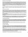
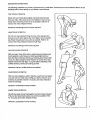
The following stretches can provide a good warm-up or cool-down. Correct form for each stretch is shown in the
drawings below. Move slowly as you stretch-never bounce.
TOE TOUCH STRETCH
Stand with your knees bent slightly and slowly bend forward
from your hips. Allow your back and shoulders to relax as you
reach down toward your toes as far as possible. Hold for 15
counts, then relax. Repeat 3 times.
Stretches: Hamstrings, back of knees and back.
HAMSTRING
STRETCH
Sit with one leg extended. Bring the sole of the opposite foot
toward you and rest it against the inner thigh of your extended
leg. Reach toward your toes as far as possible. Hold for 15
counts, then relax. Repeat 3 times for both legs.
Stretches: Hamstdngs, lower l_ack and groin.
CALF/ACHILLES
STRETCH
With one leg in front of the other, reach forward and place your
hands against a wall. Keep your back leg straight and your
back foot flat on the floor. Bend your front leg, lean forward and
move your hips toward the wall. Hold for 15 counts, then relax.
Repeat 3 times for both legs. To cause further stretching of the
achilles tendons, bend your back leg as well.
Stretches: Calves, achilles tendons and ankles.
QUADRICEPS
STRETCH
With one hand against a wall for balance, reach back and grasp
one foot with your other hand. Bdng your heel as close to your
buttocks as possible. Hold for 15 counts, then relax. Repeat 3
times for both legs.
Stretches: Quadriceps and hip muscles.
INNER THIGH STRETCH
Sit with the soles of your feet together and your knees outward.
Pull your feet toward your groin area as far as possible. Hold
for 15 counts, then relax. Repeat 3 times.
Stretches: Quaddceps and hip muscles.
I
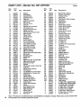
PART LISTmModel No. 831.297540
"Key
No.
Pa_
No.
1
120554
2
120202
3
120244
4
120245
5
111869
6
120203
7
120489
8
013141
9
120769
10
120552
11
-117988
12 '. 115480
13
119038
14
121078
15
120239
16
031229
17
109382
18
019084
19
119163
20
119014
21
120773
22
112609
23
014127
24
119015
25
013162
26
014132
27
120003
28
120311
29
119013
30
113203
31
_117806
32 I 108080
:33 _ 120243
34
120642
35
107503
36
119026
37
012056
38-120767
39
119416
40
052017
41
013547
42
012149
43
119020
44
120729
45
119769
46
013510
47
121728
48
013132
49
119502
50
NSP
51
120195
52
122201
53
122197
54
115945
55
120241
56
120471
18'
-.
Qty.
2
1
2
2
6
1
1
4
1
1
1
1
1
1
1
1
1
1
1
1
1
1
5
1
23
4
4
1
I
2
2
6
1
1
1
1
6
1
1
2
3
5
1
1
1
4
2
4
4
1
1
1
1
1
1
2
Description
Endcap
Left Upright
Console Knob
Upright Endcap
Cage Nut
Console Crossbar
Wire Cover
Console Screw
Console
Console Wire Harness
24" Cable Loom
Upright Wire Harness
Safety Key/Clip
Pulse Sensor/Clot, hes Clip
Right Upright
Power Cord
Circuit Breaker
Grommet
On/Off Switch
Front Left Endcap
Front Roller/Pulley
Front Roller Adj. Bolt
Roller Adj. Washer
Front Right Endcap
Safety Cover Screw
Upright Washer
- 3/8" x 3 1/2" Bolt
Power Board-Controller Wire
Bai:t Guide
6" Cable Loom
Wheel Bolt
Screw
Right Rear Belt Tension Bolt
Electronics Bracket
Motor Swivel Bolt
Bracket
Wheel Nut/Cushion Foot Nut
Controller
Safety Cover Bracket
Front Wheel
Leg Bolt/Motor Tension Bolt.
Leg Nut/Motor Tension Nut
Incline Leg
Power Board
20" Wire Harness
Power Board Screw
Cushion Foot Cover
Cover Screw
Power Board Spacer
Frame
Front Safety Cover
Rear Safety Cover
Right Foot Rail
Walking Belt
Adj. Bolt Guide
Deck Shim
R994A
Key
No.
Part
No.
Qty.
57
58
59
60
61
62
63
64
65
66
67
68
69
70
71
72
73
74
75
76
77
78
79
80
81
"' 82
83 "
84
85
86
87
88
89
9O
91
92
93
94
. 95
96
97
98
99
100
101
102
193
#
#
#
#
#
#
#
#
#
120242
120492
013141
012096
102633
102959
102955
012152
109370
116892
119375
119487
114270
120481
120483
122202
110926
119017
115046
016029
016057
013206
116927
013540
119296
119016
120194
122205
119779
129844
120866
120482
122196
120867
116633
113278
106939
100994
120740
120197
120653
122125
105477
014086
121375
121617
122331
101799
107771
101897
109407
101951
102634
118201
112083
120208
1
1
4
1
2
2
2
2
1
1
2
1
2
1
2
2
4
1
2
2
5
1
1
1
1
1
1
1
8
1
4
1
1
1
1
1
1
2
1
1
1
1
2
4
2
1
2
1
1
1
1
1
1
1
1
1
Description
Belt Tension Spring
Cushion Foot Rod
Endcap Screw
Spring Nut
Optic Switch Wire Harness
Small Bolt
Optic Switch
Small Nut
Incline Optic Switch
Incline Motor Bracket
Incline Motor Bolt
Incline Motor
Incline Motor Spacer
Bar Endcap
Cushion Foot Insert
Foot Rail Bracket
Cushion Foot Bolt
Right Rear Endcap
Cushion Foot
.4" Cable Tie
8" Cable Tie
Left Rear Belt Tension Bolt
Tie Block
Tie Block Screw
Cable Tie
Left Endcap
Rear Roller
Walking Platform
Platform Screw
Belt Tool
Electronics Screw
Cushion Knob
Left Foot Rail
Motor Tension Nut
Motor Mounting Bracket
Pulley/Flywheel/Fan
Motor Belt
Motor Bolt
Motor
Speed Disk
Optic Switch Bracket
Optic Switch Bracket Nut
Motor Nut
Flat Washer
Head Band
Video Cassette
Rod Sleeve
9" Black Wire, Male/Female •
8" White Wire, Male/Female
14" white Wire, 2 Female
4" Black Wire, 2 Female
8" Black Wire, 2 Female.
8" Green Ground Wire
8" Red Wire, Male/Female
8" Blue Wire, 2 Female
Owner's Manual
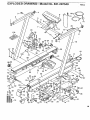
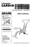
Note: '#" indicates a non-illustratedpart. Specifications are subject to change without notice. See the back cover
for information about ordering replacement parts.
EXPLODED
DRAWINGmModel
No. 831.297540
R994A
9
2
5
6
14
4
3O
93
94
102
10
\
11
3
95
97 64
'100 91
27
61
62
100
16
17
41
89
88 32
54
84
86
23
/
26
52 51
53
60
5O
82
39
87
75
69
19
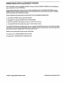
ORDERING REPLACEMENT
•
_
PARTS
.
Each TREADMILL has its own MODEL NUMBER. Always mention this MODEL NUMBER when requesting service or repair parts for your TREADMILL.
All parts listed herein can be ordered through SEARS, RoEBucK AND CO. SERVICE CENTERS and most
SEARS RETAIL STORES. If parts you need are not stocked locally, your order will be transmitted to a SEARS
PARTS DISTRIBUTION CENTER for handling.
WHEN ORDERING REPAIR PARTS, ALWAYS GIVE THE FOLLOWING INFORMATION:
1. The MODEL NUMBER of the product (831.297540).
2. The NAME of the product (SEARS LS ELITE 780 treadmill).
3. The PART NUMBER of the part(s) from page 14 of this owner's manual.
4. The DESCRIPTION of the part(s) from page 14 of this owner's manual.
Your SEARS TREADMILL has added value when you consider that SEARS has service units nationwide, staffed
with SEARS trained technicians specifically trained on SEARS products, having the pads, tools and equipment to
ensure that we meet our pledge to you: "We service what we sell. =
Should you ever need repair service or pads, call toll free:
For repair service: 1-800-4-REPAIR (1-800-473-7247)
For repair parts: 1-800-FON-PART (1-800-366-7278)
Part_lo._120208
R994A Printed in USA
© 1994 Sears, Roebuck and Co.