1
Controls and Functions
MONO INPUT CHANNEL SECTION
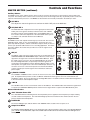
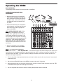
The following section details each part of the MDR8’s MONO INPUT CHANNELS including the GAIN control, 3BAND EQ, AUX sends, RECORD, PAN and LEVEL controls. The input channels one through four on the MDR8
feature high quality, discrete transistor pre-amp providing transparency and extended dynamic range. The combination connector accepts a standard XLR mic cable for microphone level signals, or a standard 1/4" phone
cable,either balanced (TRS – TIP/ RING/SLEEVE) or unbalanced (TS – TIP/SLEEVE) for line level signals.
1
GAIN
The MDR8’s pre-amp stage has a variable GAIN control with a range of 5 to
60dB on the MIC input and –26 to +26dB on the LINE input.
2
1
CLIP LED
The MDR8’s MIC/LINE pre-amp also includes a CLIP LED which, when illuminated, indicates that the signal is peaking or overloading. To reduce distortion,
lower the GAIN control to keep this LED from staying on.
3
CHANNEL EQUALIZER
The MDR8 input channels feature a 3-band equalizer allowing you to adjust the
high, mid, and low frequencies independently on each channel. The channel’s
frequency response is flat when the knobs are in the "12:00" position. Rotating
the knob towards the right will boost the corresponding frequency band by
15dB, and rotating it towards the left will cut the frequency by 15dB. The frequency centers, range of boost or cut, and equalizer type for each band are as
follows:
High: 12KHz +/- 15dB shelving type
Mid: 2.5KHz +/- 15dB peaking type
Low: 80Hz +/- 15dB shelving type
4
LOW CUT FILTER
3
5
Each of the MDR8’s channels include a LOW CUT (or high pass) filter which
rolls off the low frequencies from 80Hz and below at the rate of 12dB per
octave.
5
2
4
6
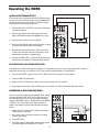
AUX 1/MON SEND
The MDR8 has two auxiliary sends which can be used for sending signals to the external effects devices or
for creating a monitor mix. The AUX1/MON section is often used for a monitor mix in a live sound mixing, or
for a headphone mix in a recording application. Each input channel includes an AUX 1/Mon send which controls the amount of that channel’s signal that is sent to the AUX 1/Mon bus. The Input channel’s AUX 2/Mon
sends are mixed together and are sent to the AUX 1 OUT jack.
6 AUX 2 / DSP Send
The MDR8 provides high quality, 24 Bit digital effects, and the level of effects can be set independently on
each channel. The channel’s AUX 2/DSP knob controls the amount of signal that is sent to the AUX
2/DSP bus. The signal of the AUX 2/DSP bus is routed to the internal DSP effects section for onboard signal processing. The AUX 2/DSP signal can also be sent to an external effect device connected to the
AUX 2 OUT jacks located in the MASTER SECTION jack field.
6