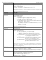
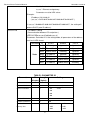
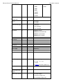
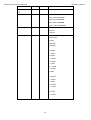
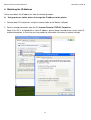
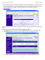
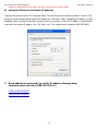
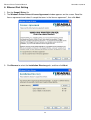
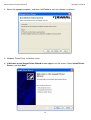
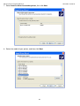
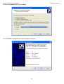
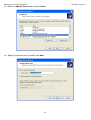
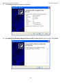
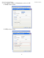
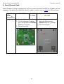
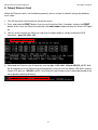
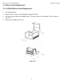
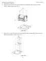
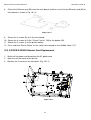
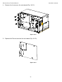
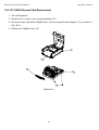
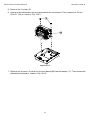
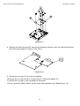
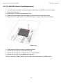
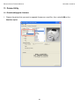
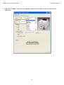
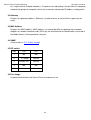
1
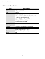
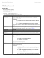
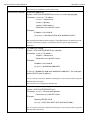
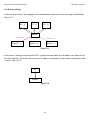
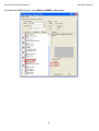
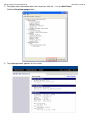
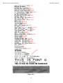
Ethernet Printer
User’s Guide
Version 1.03
Ethernet Printer Technical Manual
November 10, 2010
Table of Contents
1. ETHERNET CARD SPECIFICATIONS
2. ADDITIONAL COMMANDS
TABLE1: PARAMETER ID
TABLE 2
3. ETHERNET PRINTER STATUS/ACTIVITY INDICATORS
3.1 Ethernet Module Status/Activity indicators
3.2 Printer Status/Activity indicators
4. OBTAINING THE IP ADDRESS
5. INFORMATION AND SETTING
6. ETHERNET PORT SETTING
7. LCD ETHERNET SETTING
8. RESET ETHERNET CARD
9. REBOOT ETHERNET CARD
10. ETHERNET CARD REPLACEMENT
10.1 A-2240E Ethernet Card Replacement
10.2 X-2300E/X-3200E Ethernet Card Replacement
10.3 CP-2140E Ethernet Card Replacement
10.4 OS-2130DE Ethernet Card Replacement
11. PRINTER UTILITY
11.1 Download/Upgrade firmware
11.2 Printer setting
2
Ethernet Printer Technical Manual
November 10, 2010
11.3 Printer Info
12. SELF-TEST DIAGNOSIS
12.1 Perform Self-test Diagnosis
3
Ethernet Printer Technical Manual
November 10, 2010
1. Ethernet Card Specifications
Items
Specifications
CPU
32-bits, ARM-922, 100MHz
RAM
8 MBytes ( 4 M * 16Bits )
ROM
4 MBytes
Ethernet
1. Port: RJ-45 connector
2. LAN: 10/100 Mbps ( Auto Detect )
3. Protocol: ARP, IP, ICMP, UDP, TCP, HTTP, DHCP,
rawTCP, LPR, IPP, SNMPTrap
4. Mode: TCP Server/Client, UDP Client
5. Setup: HTTP Browser Setup
6. Security: Setup Password
Digital I/O Port
Digital I/O * 5, USB 2.0 * 2
Watch Dog Function
Firmware
Firmware On-line Updated Via Ethernet/USB
LED Lamp
Power
Environment
Operating Temperature: 0°C ~ 70°C,
Storage Temperature: -20°C ~ 50°C
Dimensions
67.8 x 64 x 17.2 mm ( W x L x H )
Weight
32 g
4
Ethernet Printer Technical Manual
November 10, 2010
2. Additional Commands
Parameter types:
-
None: no parameter is required
-
Signed integer. e.g. +100 or –23
-
Unsigned integer. e.g. 32
-
Signed byte. Just one byte binary data. e.g.
+3 is represented as 0x03(03H), and –1 as 0xff (0FFH).
Command
<ESC>KIZA
Description
*Enable/disable the switch detection of the print head if it is opened.
*Syntax: <ESC>KIZAm
*Parameter:
m = 0; disable the switch detection of print head if it is opened
(default)
m= 1; enable the switch detection of print head if it is opened
If this function is enabled, the label auto-calibration will be performed when the print head is
closed.
<ESC>KJA
Request the printer status through Ethernet to be displayed on the web
page. Information about the printer status is listed in TABLE1.
<ESC>KJB
End Job
<ESC>KJH
Enable the printer to check if Ethernet card is alive or not every second.
<ESC>KJI
Disable the printer to check if Ethernet card is alive or not every second.
<ESC>KJJ
Start Job
<ESC>KJK
*Reset the printer function.
*Syntax: <ESC>KJKm
*Parameter:
m=0 disable the reset function (default)
m=1 enable the reset function
This command is for printer configuration.
<ESC>KJL
*SNMP broadcasted function setting.
*Syntax: <ESC>KJLmnq
*Parameter:
m= 0, disable the Ethernet card to enquire to reset the printer
(default)
m=1, enable the Ethernet card to enquire to reset the printer.
n= 0, disable the SNMP function (default)
n=1, enable the SNMP function
q= 1~9 seconds;
5
which SNMP enquire for the
Ethernet Printer Technical Manual
November 10, 2010
printer status. (default value:1)
This command is for Ethernet card to enquire Printer.
<ESC>KJOETHERNET *Ethernet IP addresses
*Syntax: <ESC>KJOETHERNETm,m,m,m,n,n,n,n,o,o,o,o,q,q,q,q,q,q
*Parameter: “m,m,m,m,”: IP address
“n,n,n,n,”: subnet mask
“o,o,o,o,”: gateway
“q,q,q,q,”: MAC address
Parameters must be HEX values.
*Example:
IP address:192,168,0,42
(“m,m,m,m,”=”0xC0 0x2C 0xA8 0x2C 0x00 0x2C 0x2A”)
After configuring the Ethernet related settings or upgrading firmware, the Ethernet card will
send this command to the printer. Use the printer self test to get the Ethernet related
information.
<ESC>KJPETHERNET
* IP addresses setting.
*Syntax: <ESC>KJPETHERNETa,a,a,a,b,b,b,b,
*Parameter: “a,a,a,a,”: IP address
“b,b,b,b,”: subnet mask
Parameters must be HEX values.
*Example:
IP address:192,168,0,42
(“a,a,a,a,”=”0xC0,0xA8,0x00,0x2A)
If “a,a,a,a,”=”0x00 0x2C 0x00 0x2C 0x00 0x2C 0x00 0x2C”, the setting will
become DHCP (auto IP address).
You can send this command to Ethernet card through PC; use the printer self test to get the
Ethernet related information.
This command is for configuring the Ethernet card.
<ESC>KJQETHERNET *Ethernet card gateway setting.
*Syntax: <ESC>KJQETHERNETc,c,c,c,
*Parameter: “c,c,c,c,”: Ethernet card gateway
Parameters must be HEX values.
*Example:
Gateway:255,255,248,0
(“c,c,c,c,”=”0xFF 0x2C 0XFF 0x2C 0xF8 0x2C 0x00”)
You can send this command to Ethernet card through PC; use the printer self test to get the
Ethernet related information.
6
Ethernet Printer Technical Manual
November 10, 2010
This command is for configuring the Ethernet card.
<ESC>KJR
* Ethernet card version.
*Syntax: <ESC>KJRm,nn
*Example: <ESC>KJR5,21; Ethernet card version is 5,21.
After upgrading the firmware, the Ethernet card will send this command to the printer. Use the
printer self test to get the Ethernet card version.
<ESC>KJS
Start Page
<ESC>KJT
End Page
<ESC>KJU
*Ethernet SNMP function
*Syntax: <ESC>KJUmn
m=0, disable the Ethernet SNMP function (default)
m=1, enable the Ethernet SNMP function
n= 1~9 seconds;
which the SNMP enquire for the
printer status. (default value:1)
If n=0x0D, this indicates n=1 second. In other words, if n is not
defined, n=1 second.
This command is for printer configuration.
<ESC>KJV
Printer aging test
<ESC>KJW
*Enquire emulation function
*Syntax: <ESC>KJWmnop
m= total emulation items; m=3~9(0x33~0x39)
Maybe the printer will have more emulation in the future.
n= PPLA emulation; n=0(0x30), PPLA emulation does not exist.
.n=1(0x31), PPLA emulation is used.
o= PPLB emulation; o=0(0x30), PPLB emulation does not exist.
o=1(0x31), PPLB emulation is used.
p= PPLZ emulation; p=0(0x30), PPLZ emulation does not exist.
. p=1(0x31), PPLZ emulation is used.
If the user sends <esc>KJW to enquire emulation through Ethernet card, the printer returns
<esc>KJW3011; This represents that the printer supports 3 emulations but only PPLB and
PPLZ are used in the printer now.
<ESC>KJX
Allow the printer LEDs to blink after one of the following conditions:
1. Ethernet card upgrading process is complete.
2. IP address, subnet mask and gateway configuration settings are complete.
<ESC>KJYA
* IP Address setting
(Data transfer from the printer to the Ethernet card )
*Syntax: <ESC>KJYAa,a,a,a,b,b,b,b,c,c,c,c
*Parameter: “a,a,a,a,”: IP address
7
Ethernet Printer Technical Manual
November 10, 2010
“b,b,b,b,”: subnet mask
“c,c,c,c”: Ethernet card gateway
Parameters must be HEX values.
*Example:
IP address:192,168,0,42
(“a,a,a,a,”=”0xC0 0x2C 0xA8 0x2C 0x00 0x2C 0x2A 0x2C” )
If “a,a,a,a,”=”0x00 0x2C 0x00 0x2C 0x00 0x2C 0x00 0x2C”, the setting will
become DHCP (auto IP address).
<ESC>KJYB
* IP Address setting
(Communication between PC and printer )
<ESC>KJYBm,a,a,a,a[,b,b,b,b,c,c,c,c]
*Parameter: Parameter m is the setting mode; all parameters of the address
must be in HEX format.
Parameter
Mode
m
a,a,a,a
b,b,b,b
c,c,c,c
0x31
Gateway
Ignored
Ignored
0x32 Subnet Mask
Ignored
Ignored
0x33 Subnet Mask
Gateway
Ignored
0x34
IP Address
Ignored
Ignored
0x35
IP Address
Gateway
Ignored
0x36
IP Address
Subnet Mask
Ignored
0x37
IP Address
Subnet Mask
Gateway
TABLE1: PARAMETER ID
Parameter
ID
Length
( 4 bytes) (bytes)
Settings
All Parameters
0
0
Firmware Version
2
24
( Up to 24 characters )
Printer Resolution
5
4
0: 203
4:100
1: 300
2: 600
3: 900
Standard RAM Size 7
4
4GB
Available RAM Size 8
4
4GB
Standard Flash
4
0: 2MB
A: 1GB
1: 1MB
B: 2GB
2: 4MB
C: 4GB
9
Memory Size
8
Ethernet Printer Technical Manual
November 10, 2010
3. 8MB
D: 8GB
4. 16MB
E: 16GB
5. 32MB
6: 64MB
7: 128MB
8: 256MB
9: 512MB
Available Flash
10
4
4GB
11
4
0: DT mode
Memory Size
DT/ TT
1: TT mode
Media Sensor Type 12
4
0: Reflective
1: See Through1
2: See Through2
Print Mode
14
4
00000000: Normal
10000000: Backfeed Enable
20000000: Cutter Enable
30000000:Peeler Enable
Cut Offset
16
4
Peel Offset
17
4
Vertical Offset
18
4
Horizontal Offset
19
4
TPH Offset
20
4
Print Width
21
4
10 ~ 108 (mm)
Print Length
22
4
100 (inches)
Darkness
23
4
1 ~ 15 (0~30)
Speed
24
4
1 ~ 12
Inter Font Symbol
27
4
ab00
Set
total: 4bytes
a: 1=7 bit
b: 1~19
0=8 bit
(see table2 and show symbol set)
Total Printed Label
28
4
29
4
Labels CAL. Result 31
4
(Only F20L have)
NO.
Total Printed Label
Length
abcd : total 4 bytes
ab: reflective empty value
cd: see through empty value
9
Ethernet Printer Technical Manual
Label Size
November 10, 2010
32
4
Origin Coordination 33
4
Shift
External Card
34
4
RTC card :0x3000000
Chinese font:0x2010000
Taiwan font :0x2020000
Korean font :0x2040000
Japanese font 0x2080000
Flash Module
36
4
0:External
1:Internal
2: Internal
Serial COMM.
40
8
abcd 0000
total: 8 bytes
a (Baud Rate)
b (Parity)
c (Data Bit)
d (Stop Bit)
a: 0: 9600
1: 2400
2: 4800
3: 19200
4: 38400
5: 1200
6: 115200
7: 57600
8: 600
b: 0: NONE
1: EVEN
2: ODD
c: 0: 8 BITS
1: 7 BITS
d: 0: 1 BIT
1: 2 BITS
10
Ethernet Printer Technical Manual
November 10, 2010
TABLE 2
8 bit data
Symbol Set
7 bit data
(a=0)
(Code page)
(a=1)
Symbol set
b=0
English (437)
b=0
USASCII
b=1
Latin 1 (850)
b=1
British
b=2
Slavic (852)
b=2
German
b=3
Portugal (860)
b=3
French
b=4
Canadian/French
b=4
Danish
(863)
b=5
Nordic (865)
b=5
Italian
b=6
Turkish (857)
b=6
Spanish
b=7
Icelandic (861)
b=7
Swedish
b=8
Hebrew (862)
b=8
Swiss
b=9
Cyrillic (855)
b=10
Cyrillic CIS
1(866)
b=11
Greek (737)
b=12
Greek 1 (851)
b=13
Greek 2 (869)
b=14
Latin 1 (1252)
b=15
Latin 2 (1250)
b=16
Cyrillic (1251)
b=17
Greek (1253)
b=18
Turkish (1254)
b=19
Hebrew (1255)
11
Ethernet Printer Technical Manual
November 10, 2010
3. Ethernet Printer Status/Activity indicators
3.1 Ethernet Module Status/Activity indicators
LED Status
Description
Off (both LEDs)
No Ethernet link is detected.
Green
Speed LED
On: 100 Mbps link
Off: 10 Mbps link
Amber
Link/Activity LED
On: link up
Off: link down
Flashing: active
Amber LED
Green LED
3.2 Printer Status/Activity indicators
LED Status
Blinking LED
Wait for Ready
READY
Description
The printer waits for printer to get ready.
It will take approximately 20 seconds.
12
Ethernet Printer Technical Manual
November 10, 2010
4. Obtaining the IP Address
Printer can obtain the IP addresses from the following modes:
A.
Using router or similar device to assign the IP address to the printer
1. Connect both PC and printer using the internet cable to the Router LAN port.
2. Get the related information from the PC Internet Protocol (TCP/IP) Properties.
(Note: If the PC is assigned with a static IP address, please keep a record of the current static IP
related information, in case that you may need the information to restore its original setting)
13
Ethernet Printer Technical Manual
November 10, 2010
3. Search the IP address of the Router assigned to the printer. The following is an example of using
the 3COM WL-602 Router. Launch the web browser and enter the default IP address to open the
Router homepage (For example: The default IP address of the 3COM WL-602 Router is
http://192.168.1.1)
When the printer is turned on, READY LED will blink. Wait for about 20 seconds for the system to get
ready.
4. Enter the user name and password (the default settings are “Admin”).
5. Click Log in to enter the main menu. Then click LAN setting to enter the system status menu.
6. Click DHCP Clients List to view the printer IP addresses which are assigned to the PC.
Note: When the printer obtains the assigned IP address, it is recommended to retain that IP
14
Ethernet Printer Technical Manual
November 10, 2010
address; otherwise this will delay the time for the printer to get ready.
B. Using the Ethernet card static IP address
Connect the printer and the PC using the cable. Turn on the printer and wait for about 1 minute. The
printer will automatically get the default IP addresses (192.168.1.100). The default IP address can be
modified, make sure that it connects correctly: the first 3 sections of the PC IP address should be the
same with the printer IP address (ex. 192.168.1.xxx). The subnet mask should be 255.255.255.0.
C. Send additional commands to set the IP address through other
communication interface (USB, RS-232 etc.)
<ESC>KJPETHERNET
<ESC>KJQETHERNET
15
Ethernet Printer Technical Manual
November 10, 2010
5. Information and Setting
1. Launch a browser and enter the printer IP address. You can view the Ethernet card (SERVER
STATUS) and printer (PRINTER STATUS) related status information.
16
Ethernet Printer Technical Manual
November 10, 2010
2. In the CONFIG’s TCP/IP submenu, you can configure how the Ethernet card assigns the IP
address to the PC and other related settings.
3. In the Maintenance submenu, you can update the firmware of the Ethernet card/printer.
The accumulative time will be reset if the printer shuts down. You can get this information from the
default webpage (http://192.168.1.100/systeminfo/htm) or other webpage.
When updating the firmware of the Ethernet card/printer, all status monitors including Bartender
status must be closed.
After updating the Ethernet module firmware or changing of the IP address is complete, restart
the printer and wait for about 1 minute; you will get the latest Ethernet module firmware version
or IP address by the printer self test pages.
17
Ethernet Printer Technical Manual
November 10, 2010
6. Ethernet Port Setting
1. Run the Seagull Driver file.
2. The Windows Printer Drivers\License Agreement window appears on the screen. Read the
license agreement and select “I accept the terms in the license agreement”, then click Next.
3. Click Browse to select the Installation Directory path, and then click Next.
18
Ethernet Printer Technical Manual
November 10, 2010
4. Select the appropriate options, and then click Finish to start the software installation.
5. Windows Printer Driver installation starts.
6. A Welcome to the Seagull Driver Wizard window appears on the screen. Select Install Printer
Drivers, and click Next.
19
Ethernet Printer Technical Manual
November 10, 2010
7. Select Install a driver for another printer, then click Next.
8. Select the model of your printer, and then click Next.
20
Ethernet Printer Technical Manual
November 10, 2010
9. Click the Create Port button.
10. Select Standard TCP/IP Port, and click the New Port button.
21
Ethernet Printer Technical Manual
November 10, 2010
11. A Welcome to the Add Standard TCP/IP Printer Port Wizard window appears on the screen,
click Next.
12. Enter the IP address, and then click Next.
22
Ethernet Printer Technical Manual
November 10, 2010
13. Select Standard, and then click Next.
14. Click Finish to complete the current wizard installation.
23
Ethernet Printer Technical Manual
November 10, 2010
15. Return to Specify Port window, and click Next.
16. Specify the printer name, and then click Next.
24
Ethernet Printer Technical Manual
November 10, 2010
17. Click Finish to complete the driver installation.
18. A Seagull Driver Wizard Completed Successfully window appears on the screen. Click Close.
25
Ethernet Printer Technical Manual
November 10, 2010
19. Choose Raw(R) or LPR(L) in the Protocol option, and then click OK.
19.1 Raw(R) settings as below:
19.2 LPR(L) settings as below:
26
Ethernet Printer Technical Manual
November 10, 2010
Because LPR(L) does not support the bidirectional function, you must disable “Enable
bidirectional support” option.
20. LPD/LPR setting is complete.
27
Ethernet Printer Technical Manual
November 10, 2010
7. LCD Ethernet Setting
1
LCD Function
Display
Function Options
Description
DHCP
DISABLE
If printer is not connected to a router, with
DHCP disabled, settings of IP ADDRESS,
SUBNET MASK, and DEFAULT
GATEWAY settings will be available on
LCD.
If DISABLE is changed to be ENABLE,
LCD will prompt “ETHERNET CARD
UPDATE FINISH…”
Then please reboot the printer.
ENABLE
If printer has been connected to a router,
IP address will be assigned automatically
by DHCP server after power on.
If ENABLE is changed to be DISABLE,
and then again set back as ENABLE, LCD
will prompt “ETHERNET CARD UPDATE
FINISH…”
Then please reboot the printer.
2
IP ADDRESS
xxx.xxx.xxx.xxx
3
SUBNET MASK
xxx.xxx.xxx.xxx
4
DEFAULT
GATEWAY
xxx.xxx.xxx.xxx
xxx range:0~255
When DHCP is disabled, default IP
address is 192.168.1.100.
If “_” sign appears, it means that the DHCP
setting is disabled. If not, DHCP setting is
enabled.
1. FEED/CONFIG. : change contents.
(i.e. from 000.000.000.000 to
255.255.255.255)
2. PAUSE/CALIBR. : shift “_”sign position.
(i.e. from 255.255.255.255 to
255.255.255.255)
3. CANCEL/RESET.: view next function
option. (“_” sign must be on the third
word, for example, xxx).
4. To change IP ADDRESS or
28
Ethernet Printer Technical Manual
November 10, 2010
SUBNET MASK, enter DEFAULT
GATEWAY setting, press CANCEL
button once; LCD will prompt
“ETHERNET CARD UPDATE
FINISH…”
5. Restart the printer.
Note: All settings are valid, if IP
ADDRESS, SUBNET MASK and
DEFAULT GATEWAY settings are
5
MAC ADDRESS
yyyy-yyyy-yyyy
complete and printer is restarted.
yyyy range:0000~FFFF
29
Ethernet Printer Technical Manual
November 10, 2010
8. Reset Ethernet Card
When IP address setting is complete, the user must restart the printer to check the IP address on the
webpage. If the printer cannot get the correct IP address, please reset or reboot the Ethernet Card.
Model
Reset
Procedure
OS-2130DE
X-2300E
X-3200E
A-2240E
CP-2140E
1. Remove all the printer covers.
2. Turn on the printer, and then
1. Turn on the printer, and then
press the Ethernet card
press the Ethernet card RESET
button for 2 seconds.
3. Restart the printer.
RESET button for 2 seconds.
2. Restart the printer.
30
Ethernet Printer Technical Manual
November 10, 2010
9. Reboot Ethernet Card
When the Ethernet card is not functioning normally, we can restore its default settings by following
these steps:
1. Turn off the printer and remove all the printer covers.
2. Press and hold the RESET button, then turn on the printer. After 3 seconds, release the RESET
button. At this time, the Ethernet card enters the boot loader mode and only the Green LED lights
on.
3. You can check whether the Ethernet card enter the boot loader or not by sending the DOS
command – ping 192.168.1.100.
4. Download the Ethernet card firmware by entering tftp –i 192.168.1.100 put ARGOX_v0.71. Wait
for 40 seconds to let the Ethernet card automatically restart or until the Amber LED blinks and the
Green LED lights on. (ARGOX_v0.71 is the Ethernet card firmware and it should be placed at the
corresponding working directory).
31
Ethernet Printer Technical Manual
November 10, 2010
10. Ethernet Card Replacement
10.1 A-2240E Ethernet Card Replacement
1.
Turn off the printer.
2.
Remove the 2 screws (I) on the bottom of the printer (39).
3.
Pull out the front side of the “Middle Cover” (27) then remove it from “Bottom” (39) as shown in
Fig. 10.1.1.
4.
Remove the “Middle Cover” (27).
Figure 10.1.1
32
Ethernet Printer Technical Manual
November 10, 2010
5.
Remove the 4 screws (E).
6.
Unplug all the connectors that are connected on the main board. Then remove the “Printer
Chassis” (30) as shown in Fig. 10.1.2.
Figure 10.1.2
7.
Remove the 4 screws (B) which fix the main board (43) from the bottom (39). Then remove the
defected main board as shown in Fig. 10.1.3.
Figure 10.1.3
33
Ethernet Printer Technical Manual
8.
November 10, 2010
Pull out the Ethernet card (93) from the main board, and then insert the new Ethernet card (93) to
main board as shown in Fig. 10.1.4.
Figure 10.1.4
9.
10.
11.
12.
Secure the 4 screws (B) to fix the main board.
Secure the 4 screws to fix the “Printer Chassis” (30) to the bottom (39).
Secure the 2 screws (I) to the printer bottom.
Press and click “Power Switch” on the switch hole located on the “Middle Cover” (27).
10.2 X-2300E/X-3200E Ethernet Card Replacement
1. Switch off the power and disconnect the AC power cord.
2. Open the left side cover of the printer.
3. Remove the 2 screws on the centronics (Fig. 10.2.1).
Figure 10.2.1
34
Ethernet Printer Technical Manual
November 10, 2010
4. Remove the 8 screws on the main board (Fig. 10.2.2).
Figure 10.2.2
5. Replace the Ethernet card on the main board (Fig. 10.2.3).
Figure 10.2.3
35
Ethernet Printer Technical Manual
November 10, 2010
10.3 CP-2140E Ethernet Card Replacement
1. Turn off the printer.
2. Remove the 2 screws (J) on the printer bottom (71).
3. Pull out the front side of the “Middle Cover” (3) then remove it from “Bottom” (71) as shown in
Fig. 10.3.1.
4. Remove the “Middle Cover” (3).
Figure 10.3.1
36
Ethernet Printer Technical Manual
November 10, 2010
5. Remove the 2 screws (D).
6. Unplug all the connectors that are connected to the main board. Then remove the “Printer
Chassis” (29) as shown in Fig. 10.3.2.
.
Figure 10.3.2
7. Remove the 8 screws (D) which fix the main board (69) from the bottom (71). Then remove the
defected main board as shown in Fig. 10.3.3.
37
Ethernet Printer Technical Manual
November 10, 2010
Figure 10.3.3
8. Remove the Ethernet card (82) from the main board, and then insert the new Ethernet card
(82) to the main board as shown in Fig. 10.3.4.
Figure 10.3.4
9. Secure the 8 screws (C) to fix the main board.
10. Secure the 2 screws (D) to fix “Printer Chassis” (29) to the bottom (71).
11. Secure the 2 screws (J) on the bottom of the printer.
12. Press and click “Power Switch” on the switch hole located on the “Middle Cover” (3).
38
Ethernet Printer Technical Manual
November 10, 2010
10.4 OS-2130DE Ethernet Card Replacement
1. Turn off the printer power; unplug the power cable and the USB/Ethernet/Serial cable.
2. Remove the top cover.
3. Remove the 2 screws on the base housing.
4. Remove the whole print head assembly by releasing the 4 screws on its feet.
5. Remove the 3 screws which fix the Ethernet card as shown in the illustration below.
Figure 10.4.1
6. Place the new Ethernet card to its original position.
7. Secure the 3 screws to fix the Ethernet card.
8. Secure the 4 screws to fix “Printer Chassis” to the bottom.
9. Secure the 2 screws on the bottom of the printer.
10. Press and click “Power Switch” on the switch hole located on the “Middle Cover”.
39
Ethernet Printer Technical Manual
November 10, 2010
11. Printer Utility
11.1 Download/Upgrade firmware
1. Choose the printer that you want to upgrade firmware or send files, then select LAN on the
Interface option.
40
Ethernet Printer Technical Manual
November 10, 2010
2. Enter the IP address. Now, you can upgrade firmware or send files similar with other printer
operations.
41
Ethernet Printer Technical Manual
November 10, 2010
11.2 Printer setting
If there an error occurs, the computers will simultaneously receive the error message via the Router.
(Fig.11.2.1)
Router
Media out
Printer Ribbon out
Printer Printer Fig.11.2.1
If the printer is directly connected to the PC using the Internet cable (the IP address must be set first),
turn on the printer. The printer will search the IP address automatically, and it will be ready to print after
1 minute. (Fig.11.2.2)
Printer
Fig.11.2.2
42
Ethernet Printer Technical Manual
November 10, 2010
To enable the SNMP function, select Ethernet SNMP on Port option.
43
Ethernet Printer Technical Manual
November 10, 2010
The format of the printer status or the error code response through SNMP are as follows:
This format has 8 bytes. (0x00,0x00,0x00,0x00,0x00,0x00,0x00,0x00)
HEX
Error message description
0x01
Power on
0x02
Media out
0x03
Ribbon out
0x04
Printer busy
0x05
Pause error(peeler pause)
0x06
Memory overflow
0x07
Cutter fail
0x08
TPH open
0x09
TPH too hot
0x0a~0x2f Argox define
0x30~0x7F User define
0x80~0xFF Other define
Example 1:
If the media out occurs and the printer responds “0x01 0x01”; that indicates 1
media out error has occurred.
Example 2:
If the TPH is too hot and it is opened at the same time, the printer responds
“0x02,0x08,0x09”; that indicates 2 errors have occurred. The errors are TPH
too hot and TPH open.
44
Ethernet Printer Technical Manual
November 10, 2010
11.3 Printer Info
1. Click the Search Net Printer button. On the Printer Info tab, the printer IP address is displayed.
45
Ethernet Printer Technical Manual
November 10, 2010
2. To display more information about the net printer, click the “+” on the Net Printer.
Click the Go to Homepage button.
3. The webpage below appears on the screen.
46
Ethernet Printer Technical Manual
November 10, 2010
12. SELF-TEST DIAGNOSIS
12.1 Perform Self-test Diagnosis
When the printer is first installed, a self test should be performed. To perform the self test, please
follow the below procedures:
Turn off the power.
Load the media (and ribbon, if using thermal transfer media instead of direct thermal
paper) properly.
Press and hold the FEED key, and then turn on the power.
Release the FEED key after the printer starts to print.
The configuration report should be printed as Figure 12.1.
To return the printer to its normal operation, please turn off the power and turn on the
power again or press the CANCEL key for one second. Otherwise, the printer will enter
dump mode, and all input data will not be interpreted.
.
Contents and Information of A-2240E “PPLZ Self Test Label” are as follows:
1. Printer Version Information
Displays the printer firmware version and date information.
2. Standard RAM Size
Displays the standard RAM size of the printer.
3. Available RAM Size
Displays the available memory that can be used to store the downloadable graphics, forms
and soft fonts.
4. Flash Type
Displays the flash type used in the printer.
5. Available Flash Size
Displays the available flash capacity that can be used to store the downloadable graphics,
forms and soft fonts.
6. Int. fonts
Displays the Asian font types downloaded to the printer.
47
Ethernet Printer Technical Manual
November 10, 2010
7. H. position adjust
Sets the horizontal offset when printing.
8. Sensor type
Displays sensor type in use - See-Through or Reflective.
9. Label-less Calibration Value
Checks whether the printer performs a label-less calibration or not. If not, it should be 0000.
10. Check Sum
Used to check whether the firmware flash is correct or not. It should be 0000.
11. Max Label Height
Displays the maximum printing label height.
12. Print Width
Displays the print width.
13. Label Length
Displays the height of the label size.
14. Speed
Displays the printer speed.
15. ABS. Darkness
Displays the ABS darkness level.
16. Trim. Darkness
Trims the darkness level.
17. Print Mode
Sets the print mode: TT (Thermal Transfer with ribbon) mode or DT (Direct Thermal without
ribbon) mode.
18. Print Length Meter
Displays the length printed in meters. With this information, you may check the print head
warranty. The value will not be reset even if you replace the TPH or any other components.
48
Ethernet Printer Technical Manual
November 10, 2010
19. Cut Count
Displays the amount of labels that the printer cuts off.
20. RS232 Protocols
Displays the data frame of the RS-232 interface: baud rate, parity, data bit, and stop bit.
21. Control Character
Displays the caret, delimiter and tilde control characters.
22. Font Symbol Set
Sets the symbol set of fonts.
23. Media Type
Displays the media type.
24. Reprint After Error
Displays the setting of the Reprint After Error is disabled/enabled.
25. Backfeed Disable/Enable
Enables or disables backfeed when printing.
26. Cutter Disable/Enable
Enables or disables cutter when printing.
27. Peeler Disable/Enable
Enables or disables peeler when printing.
28. Calibration Type Mode
Sets the type of the calibration mode that is used. There are four types of calibration modes.
29. Ethernet Module Version Information
Displays the Ethernet Module version.
30. IP Address
Displays the IP address to be assigned for PC.
31. Subnet Mask
Displays the subnet mask address. Subnet mask is logically visible, distinctly addressed part
49
Ethernet Printer Technical Manual
November 10, 2010
[1]
of a single Internet Protocol network. The process of sub netting is the division of a computer
network into groups of computers that have a common, designated IP address routing prefix.
32. Gateway
Displays the gateway address. Gateway is a point of entry or exit at which a gate may be
hung.
33. MAC Address
Displays the MAC address. MAC address is a unique identifier assigned to most network
adapters or network interface cards (NICs) by the manufacturer for identification, and used in
the Media Access Control protocol sub-layer.
34. SNMP
(Please refer to 11.2. Printer setting)
35. DIP switch
Sw2
ON
OFF
1
Idle
Idle
2
DT mode
Normal
3
Factory test
Normal
4
Idle
Idle
5
Add on card
Normal
36. Font Image
Used to check whether the Internal Fonts are correct or not.
50
Ethernet Printer Technical Manual
November 10, 2010
Figure 12.1.
51