1
/:/U°
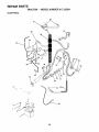
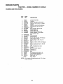
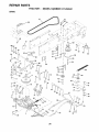
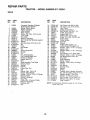
[RDF
MODEL NUMBER 917.252541
OWNER'S
• Assembly
• Operation
° Customer Responsibilities
° Service and Adjustments
° Repair Parts
Convertible
CAUTIONS Read and follow all safety rules and instructions
FOR CONSUMER
i__rr_lii
................
,
ASSISTANCE
, ,,,,,,,,,,,,,,
MANUAL
before operating
HOT LINE, CALL THIS TOLL FREE NUMBER:
........
;.
this equipment.
1-800-659-5917
......
ilj......o.........
...._;,,;
.......................
_....
SAFETY RULES
Safe Operation Practices for Ride-On Mowers
IMPORTANT: THIS CUTTING MACHINE IS CAPABLE OF AMPUTATING HANDS AND FEET AND THROWING OBJECTS.
FAILURE TO OBSERVE THE FOLLOWING SAFETY INSTRUCTIONS COULD RESULT IN SERIOUS INJURY OR DEATH.
I.
•
•
•
•
•
•
•
°
•
•
°
•
•
•
o
IIL CHILDREN
GENERAL OPERATION
Read, understand, and follow alt instructionsin the manual
and on the machine be{ore starting.
Only allow responsible adults, who are familiar with the
instructions, to operate the machine.
Clear the area of objects such as rocks, toys, wire, etc.
which could be picked up and thrown by the blade.
Besure the area isclear of other people beforemowing Stop
machine if anyone enters the area°
Never carry passengers
Do not mow in reverse unless absolutely necessary. Always
look down and behind before and while backing.
Be aware of the mower discharge direction and do not point
it at anyone, Do not operate the mower without either the
entire grass catcher or the guard in place
Slow down before turning.
Never leave a running machine unattended. Always turn off
blades, qet parking brake, stop engine, and remove keys
before o srr,_unting.
Turn off blades when not mowing.
Stop engine before removing grass catcher or unclogging
chute
Mow only in daylight or good artificial light.
Do not operate the machine while under the influence of
alcohol or drugs
Watch for traffic when operating near or crossing roadways
Use extra care when loading or unloading the machine into
a trailer or truck
Tragic accidents can occur if the operator is not alert to the
presence of children. Children are often attracted to the
machine and the mowing activity.
Never assume that
children wilt remain where you last saw them.
*
Keep children out of the mowing area and under the watchful
care of another responsible adult.
°
Be alert and turn machine off if cllildren enter the area
.
Before and when backing, look behind and down for small
children..
Never carry children. They may fall off and be seriously
injured or interfere with safe machine operation.
Never atlow children to operate the machine.
Use extra care when approaching blind corners, shrubs,
trees, or other objects that may obscure vision
o
o
°
IV.
SERVICE
•
Use extra :at _ in handling gasoline and other fuets Theyare
flammable a_d vapors are explosive
Use only an approved container
Never remove gas cap or add fuel with the engine
running. Allow engine to cool before refueling Do not
smoke
Never refuel the machine indoors
Never store the machine or fuel conlainer inside where
there is an open flame, such as a water heater
Never run a machine inside a closed area
Keep nuts and bolts, especially blade attachment bolts, tight
and keep equipment in good condition
Never tamper with safety devices
Check their I_roper
operation regularly
Keep machine free of grass, leaves, or other debris build-up.
Clean oil or fuel spillage. Allow machine to cool before
storing.
Stop and inspect the equipment if you strike an object.
Repair, if necessary, before restarting
Never make adjustments or repairs with the engine running.
Grass catcher components are subject to wea r, damage, and
deterioration, which could expose moving parts or allow
objects to be thrown. Frequently check components and
replace with manufacturer's recommended parts, when necessary.
Mower blades are sharp and can cut Wrap the blade(s) or
wear gloves, and use extra caution when servicing them
Check brake operation frequently. AdjtJst and service as
required.
•
°
11. SLOPE OPERATION
°
Slopes are a major factor related to loss-of-control
and
tipover accidents, which can result in severe injuR,' or
death. All slopes require extra caution, If you cannot back
up the slope or if you feel uneasy on it, do not mow it,
•
•
DO:
•
Mow up and down slopes, not across.
°
Remove obstacles such as rocks, tree limbs, etc.
•
Watch for holes, ruts, or bumps. Uneven terrain could
overturn the machine Tall grass can hide obstacles.
•
Use slow speed. Choose a low gear so that you wilt not have
to stop or shift while on the slope.
•
Follow the manufacturer's recommendations for wheel
weights or counterweights to improve stability
•
Use extra care with grass catchers or other attachments
These can change the stability o| the machine
°
Keep all movement on the slopes stow and gradual Do not
make sudden changes in speed or direction
°
Avoid starting or stopping on a slope if tires lose traction,
disengage the blades and proceed slowly straight down the
slope.
DO NOT:
•
Do not turn on slopes unless necessary, and then, turn slowly
and'_radualfy downhill, if possible.
•
Do not mow near drop-ells, ditches, or embankments, The
mower could suddenly turn over if a wheel is over the edge
of a cliff or ditch, or if an edge caves in.
" "
•
Do not mow on wet grass.. Reduced traction could cause
sliding.
°
Do not try to stabilize the machine by putting your foot on the
ground
•
Do not use grass catcher on steep slopes,
•
°
•
•
Look for this symbol to point out important
safety
precautions_
It
means
CAUTION!!I
BECOME ALERT!I!
YOUR
SAFETY IS INVOLVED.
11
1111
=
NUHIII,,HIII
CAUTION:
Ill
Always disconnect
=l =ill
l/HI UH="
spark plug
spark
plug in order whereitcannotcontact
to prevent accidental
wireandptacewire
starting when setting up, transporting,
adjusting or making repairs,
WARNING
The engine exhaust from this product contai ns
chemicals known to the State of California
to
cause cancer, birth defects, or other reproductive harm.
2
i
ii
I
I
i
i
iiiiiiiiii
iii
I
i[ui
..
PRODUCT SPECIFICATIONS
CONGRATULATIONS
on your purchase of a Sears
Tractor. it has been designed, engineered and manufactured to give you the best possible dependability and
performance.
Should you experience any problem you. cannot ea_sity
remedy, please contact your nearest Sears Authorized
Service Center/Department
We have competent, welltrained technicians and the proper tools to service or repair
this tractor.
Please read and retain this manual The instructions will
enable you to assemble and maintain your unit properly,
Always observe the "SAFETY RULES",
MODEL
NUMBER
HORSEPOWER:
t4 5
GASOLINE CAPACITY
AND TYPE:
5 QUARTS
UNLEADED REGULAR
OIL TYPE (APFSF/SG):
SAE 10W30 (above 32"F)
SAE 5W-30 (below 32"F)
OIL CAPACITY:
Wl FILTER:
4,0 PINTS
WiO FILTER: 3,5 PINTS
SPARK PLUG:
(GAP: 040")
CHAMPION RC12YC
VALVE CLEARANCE:
NOT ADJUSTABLE
GROUND SPEED (MPH):
FORWARD:
1st
2nd
3rd
4th
5th
6th
REVERSE:
9t7 252541
SERIAL
NUMBER
DATE OF PURC H ASE
THE MODEL AND SERIAL NUMBERS
ON A PLATE UNDER THE SEAT.
WILL BE FOUND
YOU SHOULD RECORD BOTH SERIAL NUMBER AND
DATE OF PURCHASE
AND KEEP IN A SAFE PLACE
FOR FUTURE REFERENCE,
MAINTENANCE
RESPONSIBILITIES
o
Read and observe
•
Follow a regular schedule in maintaining, caring for and
using your' tractor',
Follow the instructions under "Customer Responsibilities" and "Storage" sections of this owner's manual
°
LIMITED
the safety rules,
TWO YEAR WARRANTY
TIRE PRESSURE:
FRONT:
REAR:
14 P,SI
10 PSI
CHARGING SYSTEM:
3 AMPS BATTERY
5 AMPS HEADLIGHTS
BLADE BOLT TORQUE:
30-35 FT. LBS.
WARNING:
This tractor is equipped with an interna _
combustion engine and should not be used on or near any
unimproved forest-covered, brush-covered or grass-covered land unless the engine's exhaust system is equipped
with a spark arrester meeting applicable local or state laws
(if any), If a spark attester is used, it should be maintained
in effective working order by the operator
In the state of California the above is required by law
(Section 4442 of the California Public Resources Code)
Otherstates may have similar laws, Federal laws apply on
federal lands A spark attester for the muffler is available
through your nearest Sears Authorized Service Center/
Department (See REPAIR PARTS section of this manual)
AGREEMENT
A Sears Maintenance
Agreement is available on this product Contact your nearest Sears store for details,
CUSTOMER
1 11
1 40
2 00
3 00
4 20
5,00
t ,50
ON CRAFTSMAN
RIDING
EQUIPMENT
For two (2) years fiom the date of purchase, it this Craftsman Riding Equipment is maintained, lubricated and tuned up according
to the instructions in the owner's manual Sears will repair or replace, free of charge, any parts found to be deleclive in material
or workmanship
This Warranty does not cover:
*
.
,
.
Expendable items which become worn during normal use, such as blades, spark plugs, air cleaners belts etc
Tire replacement or repair caused by punctures from outside objects, such as nails, lhoms stumps, or glass.
Repairs necessary because of operator abuse, negligence, improper storage or accident or the failure to maintain the
equipment according to the instructions contained in the owner's manuaI
Riding equipment used for commercial or rental purposes
UMITED
90 DAY WARRANTY
ON BATTERY
For'ninety (90) days from date of purchase, if any battery included with this riding equipment proves defective in material or
workmansnip and our tesling determines the battery wil! not hold a charge, Sears will replace the battery at no charge
IN-HOME WARRANTY SERVICE ON YOUR CRAFTSMAN RIDING EQUIPMENT IS AVAILABLE AT NO-CHARGE FOR 30
DAYS FROM THE DATE OF PURCRASE
PLEASE CONTACT YOUR NEAREST SERVICE CENTER. AFTER 30 DAYS
FROM THE DATE OF PURCHASE, WARRANTY SERVICE IS AVAILABLE BY TAKING YOUR CRAFTSMAN RIDING EQUIPMENT TO YOUR NEAREST SEARS SERVICE CENTER
0N-HOME WARRANTY SERVICE WILL STILL BE AVAILABLE
AFTER 30 DAYS FROM THE DATE OF PURGHASE BUT A STANDARD TRIP CHARGE WILL APPLY ) THIS WARRANTY
APPLIES ONLY WHILE THIS PRODUCT IS tN THE UNITED STATES,
This Warranty gives you specific legal rights, and you may also have other rights which may vary from state to state
SEARS, ROEBUCK
AND CO, D/817 WA, HOFFMAN
3
ESTATES,
IL 60179
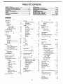
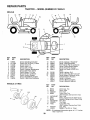
TABLE OF CONTENTS
SAFETY RULES ............................................................ 2
PRODUCT SPECIFICATIONS ...................................... 3
CUSTOMER RESPONSIBILITIES ................. ;... 3, 154 9
WARRANTY .................................................................. 3
TABLE OF CONTENTS .................................................. 4
INDEX ............................................................................
4
TRACTOR ACCESSORIES ........................................... 5
ASSEMBLY ...............................................................
7-9
OPERATION ..........................................................
10-14
MAINTENANCE SCHEDULE ..................................... 15
SERVICE AND ADJUSTMENTS ........................... 20-25
STORAGE ...................................................................
26
TROUBLESHOOTING ........................................... 27-28
REPAIR PARTS - TRACTOR ................................ 30-47
REPAIR PARTS - ENGINE ..................................... 4B-53
PARTS ORDERING/SERVICE .................. BACK PAGE
INDEX
A
Accessories
Adiustments:
Brake .......................................
22
Carburetor .............................
25
Mower:
Front-To-Back
.................... 21
Side-To-Side ....................
21
Throttle Control Cab e .............
24
Air Filler, Engine .................................. 18
Air Screen, Engine .........................
18
Assembly ...............................
7-9
B
......................................
5
Battery:
Charging
Cleaning ..................................
17
Installation...............................
9
Levels ...................................
8,16
Preparation .............................
7,8
Starting with Weak Battery ............23
Storage .............................
26
Terminals .......................
17
Bells:
Motion Drive
Removal/Replacement ......
22
Mower Blade Drive
Removal/Replacement
....
22
Blade:
Sharpening ........................
16
Replacement ............
16
Brake Adjustment
..................
22
C
........................
8
Carburetor Adjustment
.....
25
Controls, Tractor ..................
t1
Customer Responsibilities
....
15-t9
Engine:
Air Filter .............
18
Air Screen, Engine ............
18
Battery .......................
17
Cooling Fins, Engine .........
18
Engine-Oil ....................
17
Fuel Filter ....................
19
Spark Pfugs ...................
19
Tractor:
Blades ..................
16
Lubrication Chart .............
15
Mainlenance Schedule ........... 15
Tire Care ...................
9.16,23
Cutting Height, Mower ..........
12
E
Electrical:
Interlocks and Relays .............. 24
Schematic .........................
29
Wiring Diagram ..................
30
Engine:
Air Filter ........................
I8
Air Screen .....................
18,
Coo.,ng Fins, Engine ..........
18
Oil Change ...............
17
Oil Level ....................
13,17
Oi! Type ....................
17
Preparation
.........
13
Repair Parts
............
48-53
Starting ..................
14
Storage ...........
26
F
Filters:
Air ..........................
Fuel ...........................
Fuel:
18
19
Type .....................
Storage ......................
13
26
Fuse
..............................
G
Gauge Wheels .................
H
Hood Removal/Installation
..
L
Leveling Mower Deck .........
Lubrication Chart .......
M
Maintenance Schedule
Mower:
Adjustment. Front-to-Back
Adjustment, Side-to-Side
Blade Sharpening ........
Blade Replacement .....
Cutting Height ............
lnstatfation ...............
Operation ............
Removal ............
Mowing Tips ......................
Muffler ................................
Spark Arrester ..............
Mulcher Rlate ...................
4
24
9
24
2t
15
15
21
21
t6
16
12
20
13
20
14
19
3,40
9
O
Oil:
Cold Weather Conditions
Engine ................
Storage
.....
Operation ...........
Operating Mower ........
Options:
Accessories ...................
Spark Arrester .....
p
Parking Brake .............
Parts Bag ............
Parts, Replacement/Repair
,
Producl Specifications .......
R
Repair Parts ................
S
... 13,t7
17
26
I0-14
t3
5
3.40
t 1-t2
6
., 30-47
3
30-47
Safety Rules ..............
2
Seat ..............
8
Service and Adjustments ......
20-25
Brake .....................
22
Carburetor ................
25
Fuse ...........
24
Hood Removal/Installation
24
Motion Drive Belt
Removal/Replacement
22
Mower Blade Drive Belt
Removal/Replacement
22
Mower Adjustment:
Front-to*Back
.
2!
Side-to-Side
21
Mower Installation
20
Mower Removal
20
Tire Care
9.16.23
Slope Guide Sheet
55
Spark Plugs
t9
Specifications
3
Starting the Engine
13-t4
Steering Wheel
7,23
Stopping the Traclor
12
Storage
.
26
T
Throltle Conlrol Cable Adjustment
24
Tires
9,t6.23
Trouble Shooting Chart
27-28
Transaxle Repair Parts
46-47
W
Warranty ...........
3
Wiring Diagram ......................
30
Wiring Schematic
, , 29
i
ii ill/,ulll
i
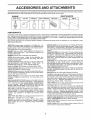
ACC
ii/n/inulliJ
RI
i llll
ill
i
i
,,,,,,,,,, ,,, ,,,,,
AND ATTACHMENTS
These accessoriesand attachments were available through most sears retail outlets and service centers when the tractor was purchased
Most Sears stores can order these items for you when you provide the model number of your tractor
MAINTENANCE
ENGINE
SPARK PLUG
GAS CAN
ENGtNE OIL
FUEL STABILIZER
AtRFILTER
BLADES
BELTS
%
PERFORMANCE
Sears offersa wide variety of attachments that fit your tractor Many of these are listed below with brief explanations of how they can help
you This list was current at the time of publication; however, it may change in future years - more attachments may be added, changes
may be made in these attachments, or some may no longer be available or fit your model Contact your nearest Sears store for the
accessories and attachments that are available for your" tractor._
Most of these attacl_ments do not require addi_iom._lhitches or conversion kits (those that do are indicateo,_ ar :! are designed for easy
attaching and detaching
AERATOR
promotes deep root growth for a healthy iawn Tapered 2 5-inch steel spikes mounted on 10-inch diameter discs
puncture holes in soil at close intervals to let moisture soak in
Steel weight tray for increased
penetration
BAGGER
tets you coilecl
grass clippings
and ]eaves
healthier, neater looking fawn Two Permanex containers
30-gallon pfastic bags
BUMPER
protects
front end of tractor
lora
hold
from damage
CARTS make hauling easy
Variety of sizes available, plus
accessories
such as side panel kits, tool caddy, cart cover,
protective mat and doily
CORING AERATOR
takes smali plugs out of soil to allow moisture and nutrients to reach grass roots
36-inch swath,
24
hardened steel coring tips t 50 Ib capacity weight tray,
EASY OIL DRAIN
VALVE
makes oil changes
easier, faster
FRONT NOSE ROLLER canters in front of mower deck to reduce
chances of "scalping" on uneven terrain
GANG HITCH lets you tow 2 or 3 pull-behind atfachments at once,
such as sweepers
dethatchers
aerators (not for use with rollers,
carts or other heavy attachments)
GAUGE WHEELS
on both sides ot the mower deck reduce
chances of "scalping" on uneven terrain For mower decks not so
equipped
MULCH RAKF_JDETHATCHER
loosens soil and flips thatch and
matted leaves to lawn surface tor easy pickup Twenty spring fine
teeth Useful to prepare bare areas for seeding. Available Ior front
or rear mounting,
HIGH PERFORMANCE
REEL-ACTION
SPRING TINE DETHATCHER
covers 36-inch wide palh and
tosses thatch into large hopper
Mounts behind tractor
MULCHING
CLOSE-OUT
PLATE KIT, once installed, lets you
mutch, discharge
or bag clippings
(bagger
optional) without
changing blades For models not equipped as 3-in-1 Convertible
mowers
See "MOWER"
in the Repair Parts section of this
manual
RAMP TOPS AND FEET let you load and unload tractor from a
pickup truck
Use with 2 x 8 or 2 x 10 lumber
ROLLER
for smoother
lawn sudace.
36-inch wide, 18-inch
diameterwater-tig!_t
drum holds up to390 Ibs. of weight Rd,unded
edges prevent harm to _ud Adjustable
scraper.automatically
cleans drum
SNOW BLAD E for snow remova! only. 14-inch high, 48-inch wide
blade clears 424nch patl_when angted left or right Raises, lowers
with side lever Adjustable skids; replaceable, reversible scraper
bar (Use with tire chains and wheel weights and/or rear drawbar
weight )
SNOWTHROWER has 40-inch swath. Drumqype auger handies
powdery and web'heavy snow Mounts easily with simple pin
arrangement Discharge chute adjusts from tractor seat 64nch
diameter spout discharges snow 10 to 50 Ieet. Lift controlled at
tractor seat, (Use with chains and wheel weights and/or rear
drawbar weight )
SPRAYERS use 12-volt DC electric to!!or that connects to the
tractor' battery or other 12-volt source
Includes booms for
automatic spraying and hand held wand for spot spraying Wand
has adjustable spray pattern. For applying herbicides, insectF
cides, fungicides and liquid fertilizers
SPREADER/SEEDERS make seeding, Ierlilizing, and weed killing easy. Broadcast spreader's are also uselu! tot granular deicers and sand
SWEEPERS let you collect grass clippings and leaves
TILLER has 5 hp engine and 36-inch swath to prepare seed beds,
cultivate and compost garden residue Tifler has its own built-in
lilt and depth control system and does NOT require a sleeve hitch
Fits any iawn, yard or garden tractor Simply hook up to the tractor
drawbar and go! Optional
accessories
convert unit for
delhatching, aerating hilling without tools
TIRE CHAINS are heavy duty; closely spaced extra-large cross
links give smooth ride. outstanding traction
TRACTOR CAB has heavy duty vinyl fabric over tubular steel
frame, ABS piastic top; clear plastic windshield offers 360 degree
visibility Hinged metal doors with catch. Keeps operator warm
and dry Remove vinyt sides and windshields for use as sun
protector in summer
Optional accessories include:
tinted/
tempered solid safety glass windshield with hand operated wiper;
12-volt amber caution tightfor mounting on cab top
VACS for powedul collection of heavy grass clippings and leaves
Optional wand attachment to pick up debris in hard-to:reach
places VAC/CHIPPER includes a chipper-shredder
WEIGHT BRACKET tot diawbar for snow removal appfications
Uses (1) 55 Ib weight
WHEEL WEIGHTS for rear wheels provide needed traction for
snow removal or dozing heavy materials
...........................................
I,IIIIIIIIIIUIL
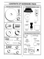
CONTENTS
Parts Bag contents
iI
III
III
I
............
,...................
: ....
. ...........
OF HAR
shown full size
Parts packed separate!Y
in carton
Seat
|
Metal
ti (2)
Sheet
Screws
/#!0-16 x 1/2
O
!
Video
Cassette
Steering
Wheel
(1) Large Rat Washer
Mulcher
Plate
f
.............
,ittll!i]
.......[iiiiii
(1) Shoulder Bolt 5/16-18
(1) Hex Bolt 1/2-13 x 1
Steering
Boot
Manual
Parts Bag
NNmlNIII
II
Parts bag contents
(1) Lock Washer
112
not shown full size
'_ x(2)Washers
7/8 x 14 Gauge
3t8
(1) Washer 17/32 x 1-3/16 x 12 Gauge
(2) Shoulder
Bolts
..,
.-
(2) Screws #10 x 5/8
(2) Lock Washers #10
, +
(2) Weld Nuts #10 C
Centerlock Nuts
/q_,
3/16 x 3/4 x16 Gauge-- _
(2) Hex Bolts 1/4-20 x 3/4
_(2)
_ok
................
@
Assemblys
@
(2) Hex Nuts 1/4-20
Slope Sheet
6
':,: Steering
',\ Wheel
____// Insert
U
U
(2) Keys
Steering
Bushing
I(2) Washers 9/32 x 5/8 x 16 Gauge _==_//
,...............
(,,2)Lock,,Washers....!/4
\.
//
(:'
_,
Washers
i,ll,,,,,,,,,,
(2) Gauge
Wheels
Steering Wheel
Adapter
4
__)
Ul
ASSEMBLY
J ii
i
i ii,l,,nm
......................................
i
..............................
Your new tractor has been assembled at the factory with exception of those parts left unassembled for shipping purposes
To ensure safe and proper operation of your tractor all parts and hardware you assemble must be tightened securely, Use
the correct tools as necessary to insure proper tightness.
TOOLS
REQUIRED
FOR ASSEMBLY
STEERING
A socket wrench set will make assembly easier. Standard
/_
r_
wrench sizes are listed,
(1) 5/16" wrench
(1) 3/4" Socket w/drive rachet
(2) 7/16" wrenches
Phillips Screwdriver
(1)
Tire pressure gauge
1/2" wrench
LARGE FLAT
WASHER
STEERING
WHEEL
Utility knife
(1) 9/16" wrench
When right or left hand is mentioned in this manual, it
means when you are in the operating position (seated
behind the steering wheel)
TO REMOVE
UNPACK
TRACTOR
STEERING
BUSHING
STEERING
WHEEL
ADAPTER
SCREW
FROM CARTON
CARTON
=
Remove afl accessible loose parts and parts cartons
from carton (See page 6).
,,
Cut, from top to bottom, along lines on all four corners
of carton, and lay panels flat.
Check for any additional loose parts or cartons and
remove
°
WHEEL INSERT
3t8-24 LOCKNUT
SHAFT
I
HOLE
POSITION)
BEFORE ROLLING TRACTOR OFF SKID
ATTACH STEERING
°
-
STEERING
SHAFT
(SHIPPING
POSITION)
WHEEL (See Fig. 1)
Slide the steering bushing over the steering shaft.
Raise steering shaft forward until screw holes in dash
line up with steering bushing, Install two (2) sheet
metal screws and tighten securely
FIG. 1
°
Position steering boot over steering shaft,
HOW TO SET UP YOUR TRACTOR
•
Place tabs of steering boot over tab slots in dash and
push down to secure
CONNECT
•
•
Slide steering wheel adapter onto upper steering shaft,.
Position front wheels of the tractor so they are pointing
straight forward
°
Position steering wheel so cross bars are horizontal
(left to right) and slide onto adapter
°
Assemble large flat washer and 3/8-24 iocknut and
tighten securely
Snap steering wheel insert into center of steering
wheel
°
Remove protective plastic from tractor hood and grill.
IMPORTANT:CHECK FOR AND REMOVE ANY STAPLES
IN SKID THAT MAY PUNCTURE TIRES WHERE TRACTOR
IS TO ROLL
OFF
TO ROLL
TRACTOR
°
,
°
•
SKID
OFF SKID
Remove banding holding discharge guard up against
tractor-
(See Figs.
2A and 2B)
nals, Before connecting battery, reCAUTION:
move
metalDo bracelets,
not short battery
wristwatch
termibands, rings, etm
Positive terminal must be connected
first to prevent sparking from accidental grounding°
:
.
°
=
°
(See Fig, 8)
Raise attachment lift lever to its highest p_sitiOnr
Release parking brake by depressing clutch/brake
pedal,
Place gearshift lever in neutral (N) position.
Roll tractor backwards off skid
BATTERY
°
•
°
,,H,.i
Hi
,,
i
,
Remove cardboard packing from seat pan and iift seat
pan to raised position.
Open battery box door
Remove terminal protective caps and discard
If this battery is put into service after month and year
indicated on label (label located between terminals)
charge battery for minimum of one hour at 6-10 amps,
First connect RED battery cable to positive (+) terminal
with hex bolt, flat washer, lock washer and hex nut as
shown Tighten securely.
Connect BLACK grounding cable to negative (-) terminal with remaining hex bolt, flat washer, lock washer
and hex nut Tighten securely
Close batten./box door.
i //
i//
/i
i
,.lllll,i,
...................
Open battery box door for:
•
Inspection for secure connections (to tighten hardware),
°
inspection for corrosion.
•
Testing battery,
° Jumping (if required).
°
Periodic charging,
SEAT
SEAT PAN
SHOULDER
BOLT
DISCARD TERMINAL PROTECTIVE CAPS
POSITIVE
(RED) CABL>
._
HEX
NUT
WASHER
LOCKFLAT
WASHER
LOCK WASHER
ADJUSTMENT
BOLT
LARGE FLAT WASHER
i
FIG, 3
BOLT
VENT
CHECK TIRE PRESSURE
(KEEP
CLEAN)
The tires on your tractor were overinflated at the factory for
shipping purposes Correct tire pressure is important for
best cutting performance,
NEGATIVE
(Bt.ACK) CABLE
•
FIG. 2A
Reduce tire pressure to PSI shown in "PRODUCT
SPECIFICATIONS" on page 3 of this manual.
CHECK DECK LEVELNESS
For best cutting results, mower housing should be properly
leveled. See 'q'o LEVEL MOWER HOUSING" in the
Service and Adjustments section of this manual,
SEAT
PAN
CHECK
BELTS
FOR PROPER
POSITION
OF
ALL
See the figures that are shown for replacing motion and
mower blade drive belts in the Service and Adjustments
section of this manual Verify that the belts are routed
correctly.,
BOXDOOR
CHECK
BRAKE
SYSTEM
After you learn how to operate your tractor, check to see
that the brake is properly adjusted
See "TO ADJUST
BRAKE" in the Service and Adjustments section of this
manual.,
ASSEMBLE
GAUGE
DECK (See Fig, 4)
FIG. 2B
INSTALLSEAT
(See Fig. 3)
Adjust seat before tightening adjustment bolt.
•
Remove cardboard packing on seat pan.,
.
Place seat on seat pan and assemble" shoulder bolt,,
•
Assemble adjustment bolt, lockwasherand fiat washer
loosely Do not tighten,
•
Tighten shoulder bolt securely,
° Lower seat into operating position and sit on seat,
,
Slide seat until a comfortable position is reached which
allows you to press clutch/brake pedal all the way
down,
•
•
Get off seat without moving its adjusted position.
Raise seat and tighten adjustment bolt securely.
WHEELS
TO
MOWER
Assemb e gause whee s with tractor on a flat level surface,
8
•
Adjust mower to desired cutting height (See "TO ADJUST MOWER CUTTING HEIGHT in the Operatiot_
section of this manual).
•
With mower in desired t_eight of cut position, gauge
wheels should be assembled so they are slightly off the
ground, install gauge wheel in appropriate hole with
shoulder bolt, 3/8" washer and 3/8-16 locknut and
tighten securely
-
Repeat for opposite side installing gauge wheel in
same adjustment hole,
.................................
,,,
, ...........
H
GAUGE WHEEL
MOUNTING
_]
TO
CONVERT TO BAGGING
DISCHARGING
,, .............................
OR
Simply remove mulcher plate and store in a safe place.
Your mower is now ready for discharging or installation of
optional grass catcher accessory.
NOTE: it is not necessary to change blades. The mulcher
blades are designed for discharging and bagging also.
DEFLECTOR
SHIELD
LOCKNUT
318" WASHER
, _/SHOULDER
GAUGE WHEEL
BOLT
FIG, 4
INSTALL
MULCHER
PLATE
(See Figs. 5A & 5B)
,,
Install two latch hooks to mulche[ plate using screw,
washer, lock washer, and weld nut as shown,
NOTE: Pre-assernbte weld nut to latch hook by inserting
weld nut from the top with hook pointing down..
•
Tighten hardware securely.
o Raise and hold deflector shield in upright position_
•
Place front of mulcher plate over front of mower deck
opening and stide into place, as shown,
°
Hook front latch into hole on front of mower deck..
° Hook rear latch into hole on back of mower deck.
!
CAUTION: Do not remove discharge
guard from mower. Raise and hold
guard when attaching mulcher plate
and allow it to rest on plate while in
operation.
Ju,i
|
i
LATCH
HOOKS
FIG. 5B
,/CHECKLIST
BEFORE YOU OPERATE AND ENJOY YOUR NEW
TRA CTOR, WE WISH TO ASSURE THAT YOU RECEI VE
THE BESTPERFORMANCE AND SA T/SFA CT!ON FROM
THIS QUALITY PRODUCT
PLEASE REVIEW THE FOLLOWING CHECKLIST:
v"
All assembly instructions have been completed.
,/
No remaining loose parts in carton.
¢
Batteryis properly prepared and charged
1 hour at 6 amps)
/
Seat is adjusted comfortably and tightened securely
,/
All tires are properly inflated. (For shipping purposes,
the tires were overinflated at the factory)
Be sure mower deck is properly leveled side-to-side/
front-to-rear for best cutting results (Tires must be
properly inflated for leveling)
HOOK POINTS DOWN
WELD NUT FROM THE TOP
,/
LOCK
WASHER
WELD
v'
NUT X
SCREW
,/
LATCH
'
LOCK
WASHER
WASHER
WASHER
MULCHER
PLATE
_,.__----SCREW
FIG. 5A
(Minimum
Check mower and drive belts. Be sure they are routed
properly around pulleys and inside afl belt keepers
Check wiring. See that all connections are still secure
and wires are properly clamped.
LATCH
HOOK
WHILE LEARNING HOWTO USE YOUR TRACTOR, PAY
EXTRA A TTENTION TO THE FOLLOWING IMPORTANT
ITEMS:
WELD
NUT
v"
Engine oil is at proper level,
,/
Fuel tank is filled with fresh, clean, regular unleaded
gasoline
Become familiar with all controls - their location and
function. Operate them before you start the engine..
,/
¢
Be sure brake system is in safe operating condition
i
i iiiii iiiii iii
i
i1.1 ii ....
OPERATION
i
1111111111111111
i i
ilUll i
,,, ,, ,,
........
These symbols may appear on your tractor or in literaturesuppfied with the product, Learn and understand their meaning,
$
+
BATTERY
CAUTION OR
WARNING
REVERSE
FORWARD
FAST
SLOW
ENGINE ON
ENGINE OFF
OIL PRESSURE
CLUTCH
LIGHTS ON
LIGHTS OFF
DIFFERENTIAL
LOCK
PARKING BRAKE
LOCKED
UNLOCKED
FUEL
CHOKE
MOWER
HEIGHT
R N H
REVERSE
MOWER
LIFT
NEUTRAL
ATTACHMENT
CLUTCH ENGAGED
HIGH
LOW
ATTACHMENT
CLUTCH DISENGAGED
PARKING
IGNITION
HYDROSTATIC FREE WHEEL
(Hydro Models only)
DANGER, KEEP HANDS AND FEET AWAY
10
BRAKE
OPERATION
KNOW YOUR TRACTOR
READ
THIS
OWNER'S
MANUAL
AND SAFETY
RULES
BEFORE
OPERATING
YOUR
TRACTOR
Compare the illustrationswith yourtractor to familiarize yourself with the locationsof various controls and adjustments_ Save
this manual for' future reference,
AMMETER \
IGNITION
SWITCH
\
LIFT LEVER PLUNGER
ATTACHMENT
LIFT LEVER
/
/
/
THROTTLF-JCHOKE
CONTROL
AI-rACHMENT
CLUTCWBRAKE
PEDAL
PARKING
HEIGHT
ADJUSTMENT
KNOB
BRAKE
GEARSHIFT
LEVER
FIG. 8
Our tractors conform to the safety standards of the American National Standards Institute,
GEARSHIFT LEVER: Selects the speed and direction of
tractor°
ATTACHMENT CLUTCH LEVER: Used to engage the
mower blades or other attachments mounted to your
tractor
ATTACHMENT LIFT LEVER: Used to raise and lower the
mower deck or other attachments mounted to your tractor-,
LIGHT SWITCH: Turns the headlights on and off
LIFT LEVER PLUNGER: Used to release attachme'nt !ift
lever when changing its position.
THROTTLE/CHOKE CONTROL: Used for starting and
controlling engine speed,.
CLUTCH/BRAKE PEDAL: Used for declutching and braking the tractor and starting the engine
PARKING BRAKE: Locks clutch/brake pedal into the
brake position.
IGNITION SWITCH: Used for starting and stopping the
engine,.
HEIGHT ADJUSTMENT KNOB: Used to adjust themower
cutting height.
AMMETER:
(h.
11
Indicates battery charging (+) or discharging
OPERATION
The operation of any tractor can result in foreign objects thrown into the eyes, which can
result in severe eye damage. Always wear safety glasses or eye shields while operating your
tractor or performing any adjustments or repairs. We recommend a wide vision safety mask
over the spectacles or standard safety glasses.
HOW TO USE YOUR TRACTOR
TO SET PARKING
NOTE: Under certain conditions when tractor is standingidle with the engine running, hot engine exhaust gases may
cause "browning" of grass, To eliminate this possibility,
always stop engine when stopping tractor on grass areas,
BRAKE (See Fig. 9)
Yourtractor isequipped with an operatorpresencesensing
switch. When engine is running, any attempt by the
operator to leave the seat without first setting the parking
brake will shut off the engine
•
illlllll,,,,,,,,,,,,
CAUTION: Always stop tractor completely, as described above, before leaving the operator's position; to empty
grass catcher, etc.
Depress clutch/brake pedal into full "BRAKE" position
and hold,
Place parking b ake lever in "ENGAGED" position and
release pressure from clutch/brake pedal. Pedal should
remain in "BRAKE" position. Make sure parking brake
will hold tractor secure.
TO USE THRO'fTLE
(See Fig. 9)
Always operate engine at full throttle°
ATTACHMENT CLUTCH LEVER
"ENGAGED"POSITION
THROTTL_
CHOKE
CONTROL
CONTROL
•
Operating engine at less than full throttle reduces the
battery charging rate,
°
Ful! throttle offers the best bagging and mower performance
TO MOVE
FORWARD
AND
BACKWARD
(See Fig. 9)
PARKING BRAKE
'ENGAGED"POSITION
"BRAKE"
POSITION
The direction and speed of movement iscontrolled by the
gearshift lever.
GEARSHIFT
LEVER
Start tractor with clutch!brake pedal depressed and
gearshift lever in neutral (N) position.
°
Move gearshift and range shift levers to desired position.
•
Slowly releaseclutch/brake pedalto start movement
IMPORTANT: BRING TRACTOR TO A COMPLETE STOP
BEFORE
SHIFTING
OR CHANGING
GEARS. FAILURE
TO DO SO WILL SHORTEN THE USEFUL LIFE OF YOUR
TRANSAXLE
"DISENGAGED"
POSITION
CLUTCHIBRAKE PEDAL
"DRIVE" POSITION
•
HEIGHT ADJUSTMENT KNOB
FIG. 9
TO ADJUST MOWER CUTTING
(See Fig. 9)
STOPPING
(See Fig. 9)
MOWER BLADES °
The cutting height is controlled by turning the height adjustment knob in desired direction
Move attachment clutch lever to "DISENGAGED" position..
GROUND DRIVE o
°
•
Turn knob clockwise (("-_) to raise cutting height.
°
Turn knob counterclockwise ()#---,,,)to lower cutting
height.
Dep_ressclutch/brake pedal into full "BRAKE" position
°
Move gearshift
ENGINE -
The cutti ng height range is approximately 1-I/2" to 4". The
heights are measured from the ground to the blade tiu with
the engine not running. These heights are approximate
and may vary depending upon soil conditions, height of
grass and types of grass being mowed
lever to neutral (N) position.
Move throttle control to slow (_)"
position.
NOTE: Failure to move throttle control to stow (,,J_.)
position and allowing engine to idle before stopping may
cause engine to "backfire".
°
Turn ignition key to "OFF" position and remove key.
Always remove key when leaving tractor to prevent
unauthorized use.
°
Never use choke to stop engine.
HEIGHT
12
•
The average lawn shoutd be cut to approximately 2-1/2
inches during the coal season and to over 3 inches
during hot months. For healthier and better looking
lawns, mow often and after moderate growth.
°
For best cutting performance, grass over 6 inches in
height should be mowed twico Make the first cut
relatively high; the second to desired height.
OPERATION
TO OPERATE
Move gearshift lever to 1st gear. Be sure you have
allowed room for tractor to roll slightly as you restart
movement
MOWER (See Fig. 10)
Your tractor is equipped with an operator presence sensing switch. Any attempt by the operator" to leave the seat
with the engine running and the attachment clutch engaged
will shut off the engine,
o Select desired height of cut.,
= Lower mower with attachment tilt control.
•
Start mower blades by engaging attachment clutch
control.
,,
TO STOP MOWER BLADES - disengage attachment
clutch control.
°
o
Make all turns slowly..
TO TRANSPORT
CAUTION: Do not operate the mower
without either the entire grass catcher,
on mower's so equipped, or the discharge guard in place.
ATTACHMENT CLUTCH LEVER
"DISENGAGED" POSITION
"ENGAGED"
POSITION
To restart movement, slowly release parking brake and
clutch/brake pedal.
•
Raise attachment lift to highest position with attachment lift control.
•
When pushing or towingyour tractor, be sure gearshift
lever is in neutral (N) position,
o
Do not push or tow tractor at more than five (5) MPH
NOTE: To protect hood from damage when transporting
your tractor on atr uck or a traile °,be sure hood is closed and
secured to tractor. Use an appropriate means of tying hood
to tractor (rope, cord, etc).
BEFORE
ATTACHMENT
LIFT LEVER
HIGH POSITION
STARTING
THE ENGINE
CHECK ENGINE OIL LEVEL (See Fig. 17)
°
,,
•
•
o
The engine in your tractor has been shipped, from the
factory, already filled with summer weight oil.
Check engine oil with tractor on level ground
Unthread and remove oit fill cap/dipstick; wipe oi! off
Reinsert the dipstick into the tube and rest oil fill cap on
the tube.. Do not thread the cap onto the tube. Remove
and read oil level, tf necessary, add oil until "FULL"
mark on dipstick is reached. Do not overfilf.
For cold weather operation you should change oil for
easier starting (See "OIL VISCOSITY CHART" in the
Customer Responsibilities section of this manual).
To change engine oil, see the Customer Responsibilities section in this manual.
ADD
GASOLINE
°
Fill fuel tank
Use fresh, clean, regular unleaded
gasoline (Useof leaded gasolinewill increase carbon
and l_.adoxide deposits and reduce valve life)
IMPORTANT: WHEN OPERATING 11',4
TEMPERATURES
DISCHARGE
GUARD
FIG. 10
TO OPERATE
4t
,_
BELOW 32°F{0_'C),
USE FRESH,
GASOLINE
TO HELP INSURE
STARTING
ON HILLS
WARNING: Experience indicates that alcohol blended
fuels (called gasohot or using ethanol or methanol) can
attract moisture which leads to separation and formation of
acids during storage. Acidic gas can damage the fue!
system of an engine while in storage To avoid engine
problems, the fuel system should be emptied before storage of 30 days or longer, Drain the gas tank, sta'rt .the
engine and let it run until the fuel lines and carburetor are
empty. Use fresh fuel next season. See Storage Instructions for additional information.. Never use engine or
carburetor cleaner products in the fuel tank or permanent
damage may occur.
hills with slopes greater than 15° and
CAUTION:
not drive
up or down
do not drive Do
across
any slope.
,,
Choose the slowest speed before starting up or down
hills.
°
°
Avoid stopping or changing speed on hills
If slowing is necessary, move throttle cor_trol lever to
slower position
•
If stopping is absolutely necessary, push clutch/brake
pedal quickly to brake position and engage parking
brake
CLEAN WINTER
GRADE
GOOD
COLD WEATHER
13
CAUTION: Fill to bottom of gas tank
filler neck° Do not overfill Wipe off any
spilled oil or' fuelo Do not store, spill or
use gasoline near an open flame.
OPERATION
TO START
ENGINE
(See Fig. 9)
•
When starting engine for the first time or if engine has run
out of fuel, it will take extra cranking time to move fuel from
the tank to the engine..
•
Depress clutch/brake pedal and set parking brake.
•
Place gearshift lever in neutral (N) position.
•
•
Move attachment clutch to "DISENGAGED" position..
Move throttle contro! lever to choke (I\1) position for
cold engine start. For warm engine start, move throttle
control to fast (,_,) position.
•
insert key into ignition and turn keyclockwise to"START"
position and release key as soon as engine starts. Do
not run starter continuously for more than fifteen
seconds per minute. If engine does not start after
several attempts, move throttle control to fast (,_)
position, wait a few minutes and try again.
•
When engine slart=_,move throttle control to desired
position.
Allow engine to warm up for a few minutes before
engaging drive or attachments.
•
,
MULCHING
FIG. 11
MOWING TIPS
IMPORTANT:
FOR BEST PERFORMANCE,
KEEP
MOWER HOUSING FREE OF BUILT-UP
GRASS AND
TRASH° CLEAN AFTER EACH USE.
NOTE: tf at a high altitude (above 3000 feet) or in cold
temperatures (below 32°F), the carburetor fuel mixture
may need tobe adjusted for best engine performance. See
"TO ADJUST CARBURETOR" in the Service and Adjust _
merits section of this manual.
The special mulching blade wilt recur the grass clippings many times and reduce them in size so that as
they fall onto the lawn they will disperse into the grass
and not be noticed. Also, the mulched grass will
biodegrade quickly to provide nutrients for the lawn.
Always mulch with your highest engine (blade) speed
as this will provide the best recutting action of the
blades
MOWING TIPS
•
When operating attachments, select a ground speed
that will suit the terrain and give best performance of
the attachment being used.
Tire chains cannot be used when the mower housing
is attached to tractor.
•
Mower should be properly leveled for best mowing
performance° See "TO LEVEL MOWER HOUSING' in
the Service and Adjustments section of this manual,
The left hand side of mower should be used for trimming_
Avoid cutting your lawn when it is wet. Wet grass tends
to form clumps and interferes with the mulching action..
The best time to mow your lawn is the early afternoon.
At this time the grass has dried and the newly cut area
will not be exposed to the direct sun.
°
Drive so that clippings are discharged onto the area
that has been cut. Have the cut area to the nghtof the
machine. This wi!t result in a more even distribution of
clippings and more uniform cutting.
For best results, adjust the mower cutting height so that
the mower cuts off only the top one-third of the grass
blades (See Fig. 12)r For extremely heavy mulching,
reduce your widlh of cut and mow siowly.
•
Certain types of grass and grass conditions may require that an area be mulched a second time to compietefy hide the clippings° When doing a second cut,
mow across or perpendicular to the first cut path.
°
Change yourcutting pattern from week to week. Mow
north to south one week then change to east to west the
next week. This witi help prevent matting and graining
of the lawn.
When mowing large areas, start by turning to the right
so that clippings will discharge away from shrubs,
fences, driveways, etc.. After one or two rounds, mow
in the opposite direction making left hand turns until
finished (See Fig. 11 ).
If grass is extremely tal!, it should be mowed twice to
reduce load and possible fire hazard from dried clippings,. Make first cut relatively high; the second to the
desired height,
Do not mowgrass when it is wet, Wet grass will plug
mower and leave undesirable clumps. Allow grass to
dry before mowing,
MAX
Always operate engine at full throttle when mowing to
assure better mowing performance and proper discharge of material. Regulate ground speed by selecting a 10w enough gear to give the mower cutting
performance as well as the quality of cut desired.
FIG. 12
14
1/3
Cheok
Brake
Oper.t_o,
V
I V'
c,ook
Ti,eF;e,_;uie
............i V'
check
f0r Loose Fasteneis
[ V
l
IV'
::
"
....
!_?
_1'
.....
LL
s.o,0oo,.o
, oeMowo,.
.......
i
,o.o.
''.i
"
Lubricaiio,
Cha.
_
....
l
c "'€,heckBa"e_to_e'iR'cho,ge
.....
! .......
...............
_
0
Clean Battery and Terminals
_
R
CheckTransaxIe
I_
Cooling
1_
Adjust Btade Belt(s) Tension
t_s
Adjusl Motion Drive Belt(s) Tensio't
_m
Check Engine Oil Level
E
_N
Change Engi[] e Oi[
..........
Clear_ Air Filter
Clean Air Screen
.........
G
!
EN
Inspect Muffler/Spark
Replace
M
V p
,V p
_,3
........
V' , •....................
V'2
v'
Arrester
Oil Filler (if equipped)
v'2
v' v'
Clean Engine Cooiing
Fins
....
Repface Spark Plug
Replace Air Fitter Paper Cartridge
Replace Fuel Fitter
t
2
3
4
* Change mote ellen when operatlng under a heavy load or in high ambienl temperatures
- Sewice mare oiten when operating in dirty or dusty conditions
- If equipped with oil filter, change oit every 50 hours
• Replace blades more often when mewing in sandy soi!
GENERAL
5 -If equippedwithadjustablesystem
6 -Not _-equlred
if equippedwithmaintenance-lreebattery
7 - Tighten#on| axlepivotbait to 35 it -Ibs maximum
Do not overtigh_en
LUBRICATION
RECOMMENDATIONS
The warranty on this tractor does not cover items that have
been subjected to operator abuse or negligence.. To
receive full value from the warranty, operator must maintain
tractor as instructed in this manual
CHART
(_
ZERK (_)
(_) FRONT
BEARING
Some adjustments will need to be made periodically to
properly maintain your tractor,
"FRONT WHEEL {.2_
BEARING ZERK
ZERK
AII adjustments in the Service and Adjustments section of
this manual should be checked at least once each season,,
ENGINE
Once a year you should replace the spark plug, clean
or replace air filter, and check blades and belts for
wear, A new spark plug and clean air filter assure
proper air-fuel mixture and help your engine run better
and last longer.
BEFORE
EACH
Check engine oil level
Check brake operation
',
Check tire pressure
Check
for loose
CLUTCH
PIVOT(S)
USE
.
,
®
PIVOTS
(_
d)
SAE 30 OR 10W30 MOTOR OiL
(_) GENERAL
fasteners
(_)
PURPOSE GREASE
(_) REFER TO CUSTOMER RESPONSIBILITIES
"ENGINE"
SECTION
IMPORTANT:
DO NOT OIL OR GREASE THE PIVOT POINTS
WHICH HAVE SPECIAL NYLON BEARINGS
VISCOUS LUBRICANTS WILL ATTRACT DUST AND DiRT THAT WILL SHORTEN
THE LIFE OF THE SELF-LUBRICATING
BEARINGS.
IF YOU
FEEL THEY MUST BE LUBRICATED,
USE ONLY A DRY POW-
15
DERED
GRAPHITE
TYPE LUBRICANT
SPARINGLY
CUSTOMER
i
H iiil_lllJ
Jlii1_1
JHI
NSIBI
+
,111
i ,11 i
i
ii
i
i
i
i i
TRACTOR
TO SHARPEN
Always observe safety rules when performingany mainte-
Care should be taken to keep the blade balanced
An
unbalanced blade will cause excessive vibration and eventual damage to mower and engine.
nance_
BRAKE OPERATION
If tractor requires more than six (6) feet stopping distance
at highspeed in highest gear, then brake must be adjusted°
(See "TO ADJUST BRAKE" in the Service and Adjust+
ments section of this manual)+
TIRES
•
Maintain proper air pressure in all tires (See "PRODUCT SPECIFICATIONS" on page 3 of this manua!)..
•
Keep tires free of gasoline, oil, or insect control chemicals which can harm rubber_
•
Avoid stump,+,., tones, deep rLts, _;harp objects and
other hazards that may cause tire damage.
BLADE (See Fig. 14)
•
The blade can be sharpened with a file or on a grinding
wheel.. Do not attempt to sharpen while on the mower.
•
To check blade balance, you will need a 5/8" diameter
steel bolt, pin, or a cone balancer.. (When using a cone
balancer, follow the instructions supplied with balancer).
•
Slide bladeon to an unthreaded portion of the steel bolt
or pin and hold the bolt or pin parallet with the ground.
If blade is balanced, it should remain in a horizontal
position° if either end of the blade moves downward,
sharpen the heavy end until the blade is balanced
NOTE: Do not u_e a nail forbalancing blade. The lobes o{
the center hole pt ]y ,_ppear to be centered, but are not
l
BLADE
CENTER HOLE
CARE
/'
/
For best results mower blades must be kept sharp. Replace bent or damaged blades.
BLADE
REMOVAL
y
(See Fig. 13)
o
Raise mower to hfghest position to allow access to
blades°
•
Remove hex bolt, lock washer and flat washer securing
blade.
•
Install new or resharpened biade with trailing edge up
towards deck as shown°
•
Reassemble hex bolt, lock washer and flat washer in
exact order as shown.
BLADE
518" BOLT
OR PIN
FIG+ 14
BATTERY
Your tractor has a battery charging system which is sufficient for normal use However, periodic charging of the
battery with an automotive charger will extend its life
o Tighten bolt securely (30-35 Ft..Lbs torque).
IMPORTANT: BLADE BOLT IS GRADE 8 HEAT TREATED.
NOTE: We do not recommend sharpening btade - but ifyou
do, be sure the blade is balanced_
MANDREL
ASSEMBLY
BLADE
/
/
•
Keep battery and terminals clean
°
Keep battery bolts tight
,
Keep small vent holes open (See "CONNECT BATTERY" in the Assembly section of this manual).
•
Recharge at 6 amperes for ! hour
TO CLEAN BATTERY AND TERMINALS
Corrosion and dirt on the battery and terminals can cause
the battery to "leak" power.
TRAILING EDGE
LOCK WASHER
FLATWASHER_
HEX
BOLT
(GRADES)*
•
Open battery box door
,
Disconnect BLACK battery cable first then RED battery cable and remove battery from tractor
•
Wash battery with solution of four tablespoons of
baking soda to one gallon of water Be careful not to get
the soda solution into the cells.
•
•
Rinse the battery with plain water and dry+
Clean terminals and battery' cable ends with wire brush
until bright
•
Coat terminals with grease or petroleum je!ly
°
Reinstall battery (See "CONNECT BATTERY" in the
Assembly section of this manual).
!
°A GRADE 8 HEAT TREATED BOLT CAN BE
IDENTIFIED BY StX LINES ONTHE BOLT HEADo
FIG, 13
16
CUSTOMER
LI ,II,L
JJJ
i !
....................
RESPONSIBI
i
V-BELTS
TO CHANGE ENGINE OIL (See Figs, 15 and t6)
Check V-belts for deterioration and wear after 100 hours of
operation and replace if necessary, The belts are not
adjustable Replace belts if they begin to slip from wear.
Determine temperature range expected before oil change.
All oi! must meet API service classification SF or SG
•
Be sure tractor is on level surface,
TRANSAXLE
.
•
Oil will drain more freely when warm
Catch oil in a suitable container,
•
Remove oil fill cap/dipstick Be carefut not to allow diit
to enter the engine when changing oil,
Remove drain plug,.
COOLING
Keep transaxle free from build-,up of dirt and chaff which
can restrict cooling.
-
ENGINE
•
After oil has drained completely, replace oil drain plug
and tighten securely.
•
Refill engine with oil through oil fill dipstick tube, Pour
slowly, Do not overfill, For approximate capacity see
PRODUCT SPECIFICATIONS" on page 3 of this
manLal
LUBRICATION
Only use high quality detergent oil rated with API service
classification SF or SG, Select the oil's SAE viscosity grade
accordir :j to your expected operating temperature.
SAE VISCOStlY
GRADES
Use gadge on oil fill cap!dipstick for- checking level
Insert dipstick into the tube and rest the oil fil! cap on the
tube, Do not thread the cap onto the tube when taking
reading, Keep oil at"FULL" line on dipstick, Tighten
cap onto the tube securely when finished.
!
-20 _
-30'
0'
-20'
TEMPERATURE
30 _
-10'
3;_* 40"
0:
RANGE ANTICIPATED
60"
10'
80 _
20"
100 _'
30"
40 =
BEFORE NEXT OIL CHANGE
AIR CLEANER
COVER
FIG. 15
NOTE: Although multi-viscosity oils (5W30, 10W30 etc)
improve starting in cold weather, these multi-viscosity oils
will result in increased oil consumption when used above
32°F. Check your engine oil level more frequently to avoid
possible engine damage from running low on oil
KNOB
. WING NUT
FOAM
PRE-CLEANER
Change the oil after the first two hours of operation and
every 50 hours thereafter or at least once a year if the
tractor is not used for 50 hours in one year,
Check the crankcase oil level before starting the engine
and after' each eight (8) hours of operation,. Tighten oil fill
cap/dipstick securely each time you check the oii level,
PAPER CARTRIDGE
R CLEANER
BASE
CAP/DIPSTICK
AIR
SCREEN
DRAIN
PLUG
FIG, t6
17
CUSTOMER
RES
BILITIES
.............
CLEAN AIR SCREEN
(See Fig. i6)
NOTE: Operating the engine with a blocked grass screen,
dirty or plugged cooling fins, and/or cooling shrouds removed will cause engine damage due to overheating
Service air cleaner more often under dusty conditions.
•
Remove knob and cover.
MUFFLER
•
Remove wing nut and air cleaner from base°
TO SERV CE PRE-CLEANER
Wash it in liquid detergent and water,
Squeeze it dry in a clean cloth.,
Inspectarid re,place corroded muffler and spark arrester (if
equipped) as it could create a fire hazard and/or damage.
SPARK PLUGS
Replace spark plugs at the beginning of each mowing
season or after every !00 hours of operation, whichever
occurs first. Spark plug type and gap setting are shown in
"PRODUCT SPECIFICATIONS" on page 3 of this manual..
•
Saturate it in engine oil. Wrap it in clean, absorbent
cloth and squeeze to remove excess oil,
TO SERVICE CARTRIDGE
.
Gently tap the flat side of the paper cartridge to dislodge dirt, Do not wash the paper cartridge or use
pressurized air, as this will damage the cartridge.
Replace a dirty, bent, or damaged cartridge,
•
Reinstall the pre-cleaner (cleaned and oiled) over the
paper cartridge.
•
Reassemble air cleaner, wing nut, cover and tighten
knob securely°
AREAS
Every 100 hours of operation (more often under extremely
dusty, dirty conditions), remove the blower housing and
other cooling shrouds. Clean the cooling fins and external
surfaces as necessary. Make sure the cooling shrouds are
reinstalled.
Your engine will not run propedy using a dirty air filter°
Clean the foam pre-cleaner after every 25 hours of operation or every season,, Service paper cartridge every 100
hours of operation or every"season, whichever occursfirst,
Slide foam pre-cleaner off cartridge.
i i ill
To insure proper cooling, make sure the grass screen,
cooling fins, and other external surfaces of the engine are
kept clean at all times,
AIR FILTER (See Fig. 16)
•
•
i
CLEAN AIR INTAKE/COOLING
Air screen must be kept free of dirt and chaff to prevent
engine damage from overheating, Clean with a wire brush
or compressed air to remove dirt and stubborn dried gum
fibers_
•
,,ll ii
18
NSIBILITIES
CUSTOMER
IH
ENGINE OIL FILTER
inlll
ill
ii i
llllll
IN-LINE FUEL FILTER
(See Fig. 17)
(See Fig, 18)
Replace the engine oil filter every season or every other oil
change if the tractor is used more than 100 hours in one
year°
•
Drain oil from engine crankcase (See "TO -CHANGE
ENGINE OIL" in this section of this manual, through
step remove drain plug)_
o Remove oil filter and wipe off filter adapter,,
The fuel filter should be replaced once each season. If fue!
filter becomes clogged, obstructing fuel flow to carburetor,
replacement is required.
•
With engine cool, remove filter and plug fuel line
section&
o
Apply a thin coating of new engine oil to the rubber
gasket on replacement oil filter,
•
°
install replacement oil _ter on filter adapter_ Turn oil
filter clockwise until rubber gasket contacts the filter
adapter, then tighten filter' an additional t/2 turn_
F_'_crankcase with new oil (See "TO CHANGE ENG;NE 3tL" in this section of Lhis manual). For approximate capacity see "PRODUCT SPECIFICATIONS" on
page 3 of this manual
•
•
.
°
Place new fuel filter in position in fuel line with arrow
pointing towards carburetor,
Be sure there are no fuel line leaks arid clamps are
properly positioned,,
Immediately wipe up any spilled gasoline.
CLAMP
CLAMP
Start the engine and check for oil leaks. Correct any
leaks before placing engine into full operation_
FUEL
FILTER
FIG. 18
CLEANING
°
Clean engine, battery, seat, finish, etc of all foreign
matter,
•
Keep finished surfaces and wheels free of al! gasoline,
oil, etc,
o
Protect painted surfaces with automotive type wax
We do not recommend using a garden hose to clean your
tractor unless the electrical system, muffler, air filter' and
carburetor are covered to keep water out Water in engine
can result in a shortened engine life,
OIL FILTER
FIG. 17
19
SERVICE AND ADjUSTM
CAUTION:
BEFORE PERFORMING ANY SERVICE OR ADJUSTMENTS:
Depress clutch/brake pedal fully and set parking brake,
Place gearshift lever in neutral (N) position_
Place attachment clutch in "DISENGAGED" position°
Turn ignition key "OFF" and remove key.
Make sure the blades and all moving parts have completely stopped°
Disconnect spark plug wire from spark plug and place wire where it cannot come in contact with
plug.
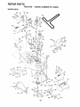
TRACTOR
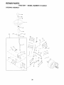
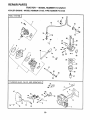
TO REMOVE
MOWER (See Fig. 19)
=VER
CLUTCH
Mower willbe easier to remove from the right side of tractor_
•
•
F'!ace attach ,_en',clutch in "DISENGAGE D" position..
Move attachment lift lever forward to lower mower to its
1owest position
•
Roll belt off engine pulley.
•
Disconnect clutch rod from clutch lever by removing
retainer spring.
Disconnect anti-sway bar from chassis bracket by
removing retainer spring,
•
°
SPRING
PULLEY
RETAINER
SPRINGS
(BOTH SIDES
Disconnect suspension arms from rear deck brackets
by removing retainer springs.
°
Disconnect front links from deck by removing retainer
springs,.
= Raise tilt lever to raise suspension arms, Slide mower
out from under tractor.
IMPORTANT:
IF AN ATTACHMENT OTHER THAN THE
MOWER IS TO BE MOUNTED TO THE TRACTOR, THE
R.H. AND L.H. SUSPENSION ARMS MUST BE REMOVED
FROM TRACTOR-
TO INSTALL
RETAINER
SPRING
ANTI-SWAY BAR
MOWER (See Fig. 19)
•
Raise attachment lift lever to its highest position.
,
Slide mower under tractor with discharge guard to right
side of tractor.
,
,
Lower lift lever to its lowest position.
install mower in reverse order of removal instructions
RETAINER
SPRINGS
(BOTH SIDES)
FIG. 19
20
sERVICE
iii ii
illllll
ii
ii
_rOLEVEL MOWER
AND ADJUSTMENTS
: ::: ................
HOUSING,
_
"
FRONT-T()-BACK ADJUSTMENT (See Figs_ 22 and 23)
IMPORTANT: DECK MUST BE LEVEL SIDE-TO-SIDE tF
THE FOLLOWING FRONT-TO-BACK ADJUSTMENT IS
NECESSARY, BE SURE TO ADJUST BOTH FRONT LINKS
EQUALLY SO MOWER WILL STAY LEVEL SIDE-TOSIDE.
To obtain the best cutting results, the mower housing
should be adjusted so that the front is approximately 1/4" to
3/4" lower than the rear when the mower is in its highest
position.
Check adjustment on right side of tractor° Measure distance "D" directly in front and behind the mandrel at bottom
edge of mower housing as shown..
°
Before making any necessary adjustments, check that
both front links are equal in length..Both links should be
approximately 10-3/8".
°
If links are not equal in length, adjust one link to same
length _ 3 other link.
° To lower front of mower loosen nut "E" on both front
links an equal number of turns_
° When distance "D" is 1/4" to 3/4" lower at front than
rear, tighten nuts "F" against trunnion on both front
links
° To raise front of mower, loosen nut"F" from trunnion on
both front links..Tighten nut "E" on both front tinks an
equal number of turns_
When distance "D" is 1/4" to 3/4" lower at front than
rear, tighten nut"F" against trunnion on both front links.
o Recheck side-to-side adjustment
Adjust the mower while tractor isparked on level groundor
driveway° Make sure tires are properly inflated (See
"PRODUCT SPECIFICATIONS"on page 3 ofthis manual).
iftires are over or underinflated, you willnot properlyadjust
your mower°
SIDE-TO_SIDE ADJUSTMENT (See Figs°20 and 21)
•
Raise mower to its highest position_
•
At the midpoint of both Sides of mower° measure height
from bottom edge of mower to ground. Distance"A" on
both sides of mower should be the same or within 1/4"
of each other_
•
if adjustment is necessary, make adjustment on one
side of mower onty.
°
To r_ise one side of mower, tighten lift link adjustment
nut _n Ihat side.
•
To lower one side of mower, loosen lift link adjustment
nut on that side.
NOTE: Each full turn of adjustment nut will change mower
height about 1/8'L
= Recheck measurements after adjusting.
BOTTOM EDGE
OF MOWER TO
GROUND
BOTTOM EDGE
OF MOWER TO
GROUND
MANDREL
GROUND
LINE
;L
FIG. 20
_\
¢_
e" '
'_i
,:
'
"
2
SUSPENSION
ARM
FIG, 22
'-....
BOTH FRONT LINKS MUST BE EQUAL IN LENGTH
LIFT LINK
ADJUSTMENT
/
NUT
FIG, 21
NUT "E"
FRONT LINKS
21
TRUNNION
FIG. 23
......................................
illll i
,,ll u i
i/ll
__
SERVICE AND ADJUSTM
,i
ll,ll,ll,ll
ill
,,llll
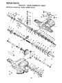
TO REPLACE
(See Fig. 24)
ii
MOWER
i
,,l,,l,,,l,,l,/H,,i,i
i
,i,,l,iN Hi
,,,,,,H,,HH,IHH
I
,,,
WITHPARKINGBRAKE "ENGAGED"
BLADE DRIVE BELT
The mower blade drive belt may be replaced without tools,
Park the tractor on level surface Engage parking brake.
BELT REMOVAL ° Remove mower from tractor (See "TO REMOVE
MOWER" in this section of this manual),
•
NUT "A"
Work belt off both mandrel pulteys and idler pulleys.
•
Pull belt away from mower,
BELT INSTALLATION •
Install new belt in reverse order of removat_
•
°
JAM NUT
Make sure belt is in all pulley grooves and inside all belt
guides
Install mower in reverse order of removal instructions.
OPERATING
ARM
FIG. 25
MANDREL
PULLEY
IDLER
PULLEYS
TO REPLACE
(See Fig. 26)
MOTION
DRIVE BELT
Park the tractoron levef surface, Engage parking brake,
For assistance, there is a belt installation guide decal on
bottom side of left footresL
MANDREL
PULLEY
Remove mower (See "TO REMOVE MOWER" in this
section of this manual,.)
.
Remove upper belt keeper°
•
•
Remove belt from stationary idler and clutching idler_
Pull belt slack toward rear of tractor. Remove belt
upwards from transaxle pulley by deflecting belt keepers,
•
Pull belt toward front of tractor and remove downwards
from around engine pulley,,
°
install new belt by reversing above procedure°
IMPORTANT: MAKE SURE UPPER BELT KEEPER IS
POSITIONED PROPERLY BETWEEN LOCATOR TABS_
FIG. 24
TO ADJUST
,,
PULLEY
BRAKE (See Fig. 25)
_LOCATOR
TABS
CLUTCHING
IDLER
Your tractor is equipped witt_ an edjustabre brake system
which is mounted on the rig; ,t si_e of the transaxle_
If tractor requires more than six (6) feet stopping distance
at high speed in highest gear, then brake must be adjusted,
°
Depress clutch/brake pedal and engage parkingbrake.
•
Measure distance between brake operating arm and
nut "A" on brake rod_
_'UPPER BELT
KEEPER
IDLER
Ifdistance is other than 1- 1/2", loosen jam nut and turn
nut "A" until distance becomes 1-1/2"o Retighten jam
- nut against nut "A".
PULLEY
Road test tractor for proper stopping distance as stated
above° Readjust if necessary. If stopping distance is
still greater than six (6) feet in highest gear, further
maintenance is necessary_ Contact your nearest authorized service center/department.
FIG. 26
22
SERVICE ANDADJUSTMENTS
'
...................
TO ADJUST
'......................................................................
STEERING
WHEEL
ALIGNMENT
TO START
The front wheel toe-in and camber are not adjustable on
your' tractor. If damage has occurred to affect the front
wheel toe_in or camber, contact your nearest authorized
service center/department
Block _p xle securely.
Remove axle cover, retaining ringand washers to atlow
wheel removal (rear wheel contains a square key- Do
not lose)
=
Repair tire and reassemble.
=
,
o
lll,i
BATTERY
If your battery is too weak to start the engine, it should be
recharged If "jumper cables" are used for emergency
starting, follow this procedure:
IMPORTANT: YOUR TRACTOR IS EQUIPPED WITH A
12 VOLT NEGATIVE GROUNDED SYSTEM. THE OTHER
VEHIC!.E MUST ALSO BE A t2 VOLT NEGATIVE
GROUNDED ,c'-YSTEM, DO NOT USE YOUR TRACTOR
BATTERY TO START OTHER VEHICLES
FOR REPAIRS
°
i
A WEAK
CAUTION: Lead-acid batteries genert
ateexplosivegases. Keep sparks, flame
and smoking materials away from bat|
terieso Always wear eye protection. "|
when around batteries.
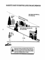
FRONT WHEEL TOE-IN/CAMBER
*
WITH
(See Fig. 28)
if steering wheel crossbars are not horizontal (left to right)
when wheels are positioned straight forward, remove steering wheel and reassemble per instructions in the Assembly
section of this manual.
TO REMOVE WHEEL
(See Fig, 27)
'........................................
ENGINE
TO ATTACH JUMPER CABLES •
On rear wheels only: align grooves in rear wheel hub
and axle. Insert square key.
Connect each end of the RED cable to the POSITIVE
(+) terminal of each battery, taking care not to short
against chassis
•
Replace washers and snap retaining ring securely in
axle groove_
Connect one end of the BLACK cable to the NEGATIVE (-) terminal of fully charged battery.
•
Connect the other end of the BLACK cable to good
CHASSIS GROUND, away from fuet tank and battery.
TO REMOVE CABLES, REVERSE ORDER
Replace axle cover.
,
WASHERS
=
RETAINING
RING
Q
AXLE COVER
BLACK cable first from chassis and then from the fully
charged battery
RED cable last from both batteries..
POSITIVE TERMINAL
NEGATIVE
TERMINAL
|
_SQUARE
(REAR
KEY
WHEEL
ONLY)
FIG_ 27
CHARGED
BATTERY
POSITIVE
TERMINAL
NEGATIVE_
TERMINAL
FIG. 28
23
SERVICE AND ADJUSTMENTS
Jill/u/l,= =
" ; _ •i
TO REPLACE
•
•
•
,
_ •
, • .......................
HEADLIGHT
•..................
,
............................................................................
BULB
Raise hood,
Pull bulb holder out of the hole in the backside of the
grill.
Replace bulb in holder and push bulb holder securely
back into the hole in the backside of the grill
Close hood_
INTERLOCKS
HOOD
HEADLIGHT
WIRE
CONNECTOR
AND RELAYS
Loose or damaged wiring may cause your tractor to run
poorly, stop running, or prevent it from starting,
•
Check
wiring°
See
electrical
wiring
diagram
in the
Repair Parts section of this manual.
TO REPLACE
F:USE
Replace with 30 amp automotive-type plug-in fuse, The
fuse holder is located behind the dash.
FIG. 29
TO REMOVE HOOD AND GRILL ASSEMBLY
(See Fig. 29)
•
Raise hood_
•
Unsnap headlight wire connector.
•
Stand in front of tractor,, Grasp hood at sides, tilt toward
engine and lift off of tractor°
•
To replace, reverse above procedures,
24
CE AND ADJUSTMENTS
+
ENGINE
TO ADJUST
ACCELERATION
THROTTLE
CONTROL
°
CABLE
(See Fig. 30)
The throttle control has been preset at the factory and
adjustment should not be necessary, Check adjustment as
described below before loosening cable. If adjustment is
necessary, proceed as follows:
•
With engine not running, move throttle control lever
from slow (._) to choke (l'_1)position. Slowly move
lever from choke (1\1) to fast (,(_) position+
•
Check to see if hole in throttle lever and hole in speed
control bracket are aligned.
°
•
High speed stop is factory
damage may result.
CARBURETOR
adjusted.
Do not adjust-+
CABLE
CLAMP
SCREW
(See Fig. 31)
The carburetor has been preset at the factory and adjustment should not be necessary However, minor adjustment may be required to compensate for differences in fuel,
temperature, altitude or load, if the carburetor does need
adjustment, proceed as foIIows:
SPEED
BRACKET
In general, turning the adjusting needles in (clockwise)
decreases the supply of fuel to the engine giving a leaner
fue!/air mixture,. Turning the adjusting needles out (counter*
clockwise) increases the supply of fuel to the engine giving
a richer fuel/air mixture_
IMPORTANT:
DAMAGE
SEATS IN CARBURETOR
TURNED IN TOO TIGHT_
THROTTLE
LEVER
TO THE NEEDLES AND THE
MAY RESULT IF NEEDLE iS
FIG. 30
PRELIMINARY SETTING +
°
Be sure you have a clean air filter and the throttle
control cable is adjusted properly (see above),
,,
With engine off turn idle fuel adjusting needle in (clockwise) closing it finger tight and then turn out (counterclockwise) 1 turn
FINAL SETTING
Start engine and allow to warm for five minutes. Make
final adjustrnents with engine running and shift/motion
control fever in neutral (N) position.
°
Idle speed set! ng - With throttle control tever in slow
(.<_) position, engine should idle at 1750 RPM If
er_ne idles too slow or fast, turn idle speed adjusting
screw in or out until correct idle is attained.
°
Idle,fuel needJ_ settin_g- With throttle control lever in
slow (.<_) position, turn idle fuel adjusting needle in
(clockwise) until engine begins to die and then turn out
(counterclockwise) approximately 1/8 to 1/4 turn to
obtain best low speed performance,.
o
IDLE SPEED
ADJUSTING
SCREW.,....
,
-
°
Recheck idle speed
(,_)
fuet
Reuntil
IMPORTANT:
NEVER TAMPER WITH THE ENGINE
GOVERNOR.
WHICH IS FACTORY SET FOR PROPER
ENGINE SPEED.. OVERSPEEDING
THE ENGINE ABOVE
THE FACTORY
HIGH
SPEED
SETTING
CAN 8E
DANGEROUS
IF YOU THINK THE ENGINE+GOVERNED
HIGH SPEED NEEDS ADJUSTING,
CONTACT
YOUR
NEAREST
AUTHORIZED
SERVICE
CENTER/
DEPARTMENT, WHICH HAS PROPER EQUIPMENT AND
EXPERIENCE
TO
MAKE
ANY
NECESSARY
ADJUSTMENTS.
tf hol_ s are not aligned, loosen cable clamp screw and
align :he holes by insertin+c a pencil or a 1/4" drill bit
through both holes,
Pull throttle cable up to remove slack and tighten cable
clamp screw Remove alignment pencil or drill bit+
TO ADJUST
TEST -
Move throttle control lever from slow (..=_) to fast
position..
If engine hesitates or dies, turn idle
adjusting needle out (counterclockwise)
1/8 turn
peat test and continue to adjust, if necessary,
engine accelerates smoothly
IDLE FUEL
ADJUSTING
NEEDLE
FIG+31
Readjust if necessary
25
ENGINE
immediately prepare your tractor for storage at the end of
the season or if the tractor will not be used for 30 days or
more.
................
iii
,_,
i
i
CAUTION:
.....
"
FUEL SYSTEM
iiiiiii,
i
Never store the tractor with
J
where
may
reach
an open
flame
gasolinefumes
in the
tank
inside
a building
or spark.
Allow the engine to Cool
before storing in any enclosure.
!J
J
!
IMPORTANT:
IT IS IMPORTANT TO PREVENT
GUM
DEPOSITS
FROM FORMING
IN ESSENTIAL
FUEL
SYSTEM PARTS SUCH AS CARBURETOR,
FUEL FILTER, _
FUEL HOSE, OR TANK DURING STORAGE.
ALSO,
EXPERIENCE
INDICATES THAT ALCOHOL
BLENDED
FUELS (CALLED GASOHOL OR USING ETHANOL OR
METHANOL) CAN ATTRACT MOISTURE WHICH LEADS
TO SEPARATION AND FORMATION OF ACIDS DURING
STORAGE.
ACIDIC GAS CAN DAMAGE
THE FUEL
SYSTEM OF AN ENGINE WHILE IN STORAGE
TRACTOR
Remove mower from tractor for winter storage. When
mower is to be stored for a period of time, clean it thoroughly, remove all dirt, grease, leaves, _tc. Store in a
clean, dry are&
° Clean entire tractor (See "CLEANING" in the Customer
Responsibilities section of this manual)°
°
Inspect and replace belts, if necessary (See belt replacement instructions in the Service and Adjustments
section of this manual)
o
Lubricate as shown in the Customer Responsibilities
section of this manual
o
NOTE: Fuel stabilizer is an acceptable alternative in
minimizing the formation of fuel gum deposits during storage. Add stabilizer to gasoiine in fue! tank or storage
container° Always follow the mix ratio found on stabilizer
container. Run engine at least 10 minutes after adding
stabilizer to allow the stabilizer to reach the carburetor. Do
not drain the gas tank and carburetor if using fuel stabilizer
ENGINE OIL
Drain oil (with engine warm) and replace with clean engine
oiL (See "ENGINE" in the Customer Responsibilities
section of this manual).
BATTERY
Fully charge the battery for storage.
After a period of time in storage, battery may require
recharging.
To help prevent corrosion and power leakage during
long periods of storage, battery cables should, be
disconnected and battery cleaned thoroughly (see 70
CLEAN BATTERY AND TERMINALS" in the Customer Responsibilities section of this manual).
°
Start the engine and let it run until the fuel lines and
carburetor are empty.
Never use engine or carburetor cleaner products in the
fuel tank or'permanent damage may occur.
Use fresh fuel next season.
•
Touch up all rusted or chipped paint surfaces; sand
lightly before painting
•
Drain the fuel tank,
•
,
Be sure that all nuts, bofts and screws are securely
fastened Inspect moving parts for damage, breakage
and wear. Replace if necessary°
•
*
CYLINDERS
•
°
Remove spark plug(s),,
Pour one ounce of oil through spark plug hole(s) into
cylinder(s).
•
Turn ignition key to"START" position for a few seconds
to distribute oil.
o
Replace with new spark plug(s)
•
After cleaning, leave cables disconnected and place
cables where they cannot come in contact with battery
terminals.
•
Be sure battery drain tube is securely attached_
•
Do not store gasoline from one season to another
°
if battery is removed from tractor for storage, do not
store battery directly on concrete or damp surfaces
•
Replace your gasoline can if your can starts to rust
Rust and/or dirt in your gasoline will cause problem&
°
If possible, store your tractor indoors and cover it to
give protection from dust and dirt
OTHER
•
Cover your tractor with a suitable protective cover that
does not retain moisture. Do not use plastic. Plastic
cannot breathe which allows condensation to form and
will cause your tractor to rust.
IMPORTANT: NEVER COVER TRACTOR WHILE ENGINE
AND EXHAUST AREAS ARE STILL WARM.
26
TROUBLESHOOTING
POINTS
PROBLEM
CAUSE
CORRECTION
WIlt not start
1
Out of fuel
2
3
4
5
6
7
Engine not "CHOKED" properly
Engine flooded
Bad spark plug
Dirty air filter
Dirty fuel filter
Water infuel
t.
2
3
4
5
6
7
8
9
10
Loose or damaged wiring
Carburetor out of adjustment
Engine valves out of adjustment
8
9
t0
Hard to start
t
2
3
4
5
6
7
8
Dirty ai fiitel
Bad sparkp_ug
Weak or dead battery
Dirty tuel filter
Stale or dirty fuel
Loose or damaged wiring
Carburetor outof adjustment
Engine valves out of adjustment
1
2
3
4
5
6
7
8
Cleaq/replace air filter
Replace spark plug
Recharge or replace battery
Replace fuel filter
Drain fuel lank and refill with fresh gasoline
Check all wiring
Contact an authorized service facility
Contact an authorized service facility
Engine will not turn over
1
2
3
4
Clutch/brake pedal not depressed
Attachment clutch is engaged
Weak or dead battery
Blown fuse
5
6
7
8
9
Corroded battery terminals
Looseor damaged wiring
Faulty ignilion switch
Faulty solenoid or starter
Faulty operator presence switeh(es)
1
2
3
4
5
6
7
8
9
Depress clutch/brake pedal
Disengage attachment ctutch
Recharge or reptace battery
Replace fuse
Clean battery terminals
Checkait wiring
Chectdreplace ignition switch
CheckJreplace solenoid or starter
Contact an authorized service facility
Engine clicks but will not
start
1
2
3
4
Weak or dead battery
Corroded battery terminals
Loose or damaged wiring
Faulty solenoid or starter
t
2
3
4
Recharge or replace battery
Clean battery terminals
Check alt wiring
Check/repface solenoid or starter
Loss of power
1
2
3
4
5
6
7
8
9
Cutting too much grass/leo last
Throttle in "CHOKE" position,
Build-up ot grass, leaves and trash under mower
Dirty air filler
Low oft leveildirty oil
Faulty spark plug
Dirty fuel fiiter
Stale or didy fuel
Water in tuet
1
2
3
4
5
6
7
8
9
Set in "Higher Cut position/reduce speed
Adjust throttle control
Clean underside of mower housing
Clean/replace air filter
Checkoil level/changeoil
Ctean and regap or change spark plug
Repiace fuel filter
Drain fuel tank and refill with fresh gasoline
Drain fuel tank and carburetor, refill tank with fresh
gasoline and replace fuet filter
Connect and fighlen spark plug wi_-a
Clean engineair sereenifins
Clean/replace muffler
Check all wiring
Contact an authorized service facility
Contact an authorized service facility
.......................................
Fill luel tank
See "TO START ENGINE" in Operat-;on section
Wait several minutes before attempting to start
Replace spark plug,
CIeantreplace air filter
Replace fuelfilter
Drain fuel tankand carburetor refill tank with fresh
gasoline and replace fuel filter
Check all wiring
Contact an authorized senlice facility
Contact an authorized service facility
ill
10
t 1
12
13
14
15
10
11
12
13
14
!5
Spark plug wire loose
Dirty engine air screen/fins
Dirty/clogged muffler
Loose or damaged wiring
Carburetor, out of adjustment
Engine valves out of adjustment
k
Excessive vibration
l
2
3
Worn, bent or loose t_lade
Bent biade mandrel
Loose/damaged part(s)
t
2
3
27
Replace blade Tighten blade boil
Replace blade mandrel
Tighten loose part(s) Replace damaged parts
TROUBLESHOOTING
....................................
PROBLEM
"_" .....
"
,Hil_llU
ill
POINTS
............
illl ii ill L
:CAUSE
...................
]_l,i
CORRECTION
i
i
i
iiiii,i]1,
i
]l]llllllii
iiiii iiiiiiii
Engine continues to run
when operator leaves seat
with attachment clutch
1
Faulty operator-safety presence control system
illlllllll
I
1,
Check wiring, switches and connections If not
corrected, contact an authorized service facility
ii ,
engaged
iii
Poor cut - uneven
i
,iUllll]l i i
ii
................................
1..
2.
Worn, bent or loose bTede
Mower deck not level,
1.
2
Reprace blade, Tighten blade bolt.
Level mower deck,
3.
4.
5
Buildup of grass, leaves, and trash under mower.
Bent blade mandrel
C{ogged mower deck vent ho_es from buildup of
grass, leaves, and trash around mandrels
3.
4_
5.
Clean underside of mower housing
Replace blade mandrel.
Clean around mandrels to open vent holes
Mower blades will not
rotate
t
2.
3.
4,
Obstruction in clutch mect'anism
Worn/damaged mower drive belt
Frozen idler pulley
Frozen blade mandrel
1.
2.
3.
4
Remove obstruction
Replace mower drive belt
Replaceidterpultey
Replace blade mandrel
Poor grass discharge
I
2
3
4
5
6
7
8.
Engine speed too slow.
Travel speed too fast
Wet grass.
Mower deck not level
Lowtuneven tire air pressure.
Worn, bent or loose blade.
Buildup of grass, leaves and trash under mower.
Mower ddve belt worn
1.
2
3.
4..
P{ace throttle control in "FAST" position
Shift to slower speed.
Allow grass to dry before mowing
Level mower deck.
9.
10.
11
Blades Improperly installed
lmproperblades used.
Clogged mower deck vent holes from buildup of
grass, leaves, and trash around mandrels,
5.
6.
7.
8..
g,
10.
1!..
Check tires for proper air pressure
Replacelsharpen blade. Tighten blade bolt
Clean underside of mower housing
Replace mower drive belt.
Retnstalf bJades sharp edge down
Replace with blades listed in this manual
Clean around mandrets to open vent holes
Headlight(s) not working
(if so equipped)
1
2
3
4
5
Switch is "OFF"
Bulb(s) burned out,
Faulty tight switch.
Loose or damaged widng
BIownfuse
t
2,.
3.
4,
5
Turn switch "ON".
Replace bulb(s)
Check/replace light switch.
Check wiring and connections
Replace fuse
Battery will not charge
1,
2.
Bad battery cell(s)
Poor cable connections
3
4
Fau{ty regulator (if so equipped)
Faulty alternator
1
2.
3
4
Replace battery.
Check/clean all connections
Rep{ace regulator.
Replace alternalor
1
Engine throttle control not set at "SLOW"
position for 30 seconds before stopping engine
I
Move lhrottle control to "SLOW" position and aIIow
to idle for 30 seconds before stopping engine
Engine "backfires"
when turning engine
"OFF"
28
uI
i
j
TRACTOR
- - MODEL
NUMBER
917.252520
SCHEMATIC
4"
"
'
•
BLACK
RED
BATTERY
REO
RED
AMMETER
I
S_TARTER
I
BLACK
:©,©'
WHITE
SOLENOID
©
_G
!
f
CLUTCH / BRACE
(PEDAL UP)
WHITE
L(
SEAT SWITCH
IGNITION SWITCH
WHITE
_
}-
(NOT OCCUPIED)
t
BLACK
I "-,('--7I
f'-,J
I BLACK _
BLACK
..............
GROUNDING
CONNECTOR
F
BLACK
IGNITION
UNIT
I
_
SPARK
PLUG ______
i
AFTER FIRE SOLENOID
CHARGING SYSTEM OUTPUT
3 AMP OC @ 36(}0 RPM
2B VOLTS AC MIN @ 3600 RPM
(CHARGING SYSTEM OtSCONNECTED)
RED
LIGHTING
SYSTEM
I
NOTE
OUTPUT
DIODE
i ALTERNATOR
5 AMP AC @ 3600 RPM _
.....................................................................
_......
YOUR TRACTOR IS
.
I
EQUIPPED WITH A SPECIAL
[w_
_t4VOLTSACMF
N '@ 3_0;RPM(UGHTS
OFF_
ALTERNATOR SYSTEM
I_
=
" .............
THE LIGHTS ARE NOT
{_
HEADLIGHTS
CONNECTED TO THE
t t ......
_
't
I BROWN
BLACK
BATTERY, BUT HAVE THEIR _I_(__
_ BR__--_--_C_
,_
OWN ELECTRICAL SOURCE
'lv
_-_'_ ',
vT
_'_u/
T
BECAUSE OF THIS, THE
HEADLIGt4T
1 /_
!
BRIGHTNESS OF THE LIGHTS
SWlTCFi
L---{(5
IGNITION SWITCH
WILL CHANGE WITH ENGINE
(OFF)
"_/
POSITION
CIRCUIT
SPEED. AT IDLE THE LIGHTS
WILL DIM. AS THE ENGINE IS
WIRING INSULATED CLIPS
..........OFF
M+G
SPEEDED UP, THE LIGHTS
ON
B+L
WILL BECOME THEIR BRIGHTEST_
NOTE: IF WIRING INSULATED
/-)
START
B+ S + L
CLIPS WERE REMOVED FOR
SERVICING OF UNIT, THEY
SHOULD BE REPLACED TO
NON-REMOVABLE
--_)----- REMOVABLE
CONNECTIONS
PROPERLY SECURE YOUR WIRING
CONNECTIONS
29
REPAIR PARTS
TRACTOR
-- MODEL
NUMBER
917.252541
i
ELECTRICAL
"
22
21
26
36
36
34
2O
39
25
31
30
"_
, _.17
/
5
!
3O
39
36
32
45
35
REPAIR PARTS
TRACTOR
- - MODEL
NUMBER
917.252541
ELECTRICAL
KEY
NO,
PART
NO.
1 121537X
2 74760412
3 STD551025
4 STD551125
5 121264X
6 STD541025
7 109238X
S 129965
9 109596X
19 STD551125
20 73350400
21 13685O
22
24
25
4152J
4799J
146147
26
28
29
30
31
32
33
34
35
36
38
39
40
4!
42
43
44
45
49
70
108824X
4207J
121305X
144921
140400
141226
140403
I10712X
108236X
STD601005
140336
109553X
146057
7111O412
131563
145673
73800400
12!433X
11151000
142621
DESCRIPTION
Battery 12 Volt 30 Amp
Bolt, Hex Head !/4-20 unc x 3/4
Washer'
Washer
Caps Battery 20/25/30/35 AMP
Nut
Tube, Plastic, !2"
Case, Battery
Clamp, Hose
Washer, Lock
Nut, Hex, Jam 1/4-20 UNC
Harness, Light Socket
(Includes Key # 33)
Bulb, Light
Cable, Battery, 6 Gauge, Red, 11"
Cable, Battery, 6 Gauge, Red, Wi
16 Wir
Fuse, 30 Amp
Cable, Ground, 6 Gauge, Black, 12"
Switch, Plunger
Switch, Ignition
Nut, Ignition
Cover, Key Switch
Key, ignition
Switch, Light
Bracket, Clutch Switch
Screw
Bracket, Interlock Switch
Switch, Interlock, Clutch, 4 Terminal
Harness, Ignition
Bolt, Hex Head, Fin. 1/4-20 x 3/4
Cover, Terminal, Red
Solenoid
Nut Lock W/Insert 1/4-20 UNC
Ammeter Rectangular 6 Amp
Washer Lock mternat Tooth 5/8
Harness Engine LTPL Koh CmdL
HL
NOTE: All component dimensions given in U.S. inches
1 inch = 25.4 rnm
31
REPAIR PARTS
TRACTOR
CHASSIS
30
-- MODEL
NUMBER
917.252541
AND ENCLOSURES
24
17
21
18
26
25
26
31
29
16
14
,3
4O
28
/%_.
"
/
g
_4
38
._
j
J
34
39
32
26
14
REPAIR PARTS
TRACTOR - - MODEL NUMBER 917.252541
CHASSIS
AND ENCLOSURES
KEY
NO,
PART
NO.
1
2
3
4
6
7
8
9
10
11
13
14
15
145501
140356
17490612
19131216
145206
126842X
126471X
145938X012
72140608
135464
126276X
17490608
74180512
16
17
18
I9
21
22
24
25
26
27
28
29
30
31
33
34
35
38
39
40
100
--
STD541431
131445X459
126938X
17521312
122933X
124479X
STD523710
19131312
STD541437
17030814
140137
124029X
147310X459
139976
145244X459
145243X459
STD533707
139886
139887
139977
105037X
5479J
DESCRIPTION
Chassis Assembly
Drawbar
Screw, Thd Roll. 3/8-16 x 3/4
Washer 13/32 x 3/4 x 16 Gauge
Saddle
Shield Ht Hood KohltDia Engine
Clip Insulator .406 t','tg Hole
Dash
Bolt, Carriage 3/8-16 x 3/4
Panel, Dash, L.H.
Panel, Dash, R.H_
ScrewThdrol 3/8-16 x 1/2
Screw, Machine, Truss Head
5/16-18 UNC x 3/4
Nut
Hood Assembly
Bumper, Hood
Screw, Sttdo Hex Hd, w/PI Washer
Rivet, Ratchet, Nylon
Washer, Nylon .28 x °75 x .19
Bolt
Washer 13/32 x !3/16 x 12 Gauge
Nut
Screw Spiderlock Hex Hd #8-7/8
Grill
Lens, Headlight Bar, Clear
Fender
Bracket, Fender Support
Footrest, LH.r
Footrest, RH,
Bolt
Pivot Bracket Assembly, LH
Pivot Bracket Assembly, RrH.
Spacer Fender Raised LT
Strip Foam I8"
Plug, Button
NOTE: All component dimensions given in U.S, inches
1 inch = 25, 4 mm
33
REPAIR PARTS
TRACTOR
- - MODEL
NUMBER
917,252541
DRIVE
57
53
i
26
27
34
REPAIR PARTS
TRACTOR - - MODEL NUMBER 917.252541
DRIVE
KEY
NO.
t
2
3
4
5
6
8
10
11
13
14
15
19
21
22
24
25
26
27
28
29
30
31
32
34
35
36
37
38
39
40
41
42
44
45
46
47
48
49
50
PART
NO.
145602
146682
123666X
12000028
12t520X
17490512
141003
76020416
105701X
74550412
STD551125
74780544
STD541437
106933X
130804
STD541237
106888X
STD551037
STD561210
145204
124236X
130807
127275X
STD523107
122424X
120183X
STD551062
STD571810
t23674X
STD523727
4470J
109070X
19131312
105706X
110812X
12000039
127783
123789X
123205X
STD523715
KEY
NO.
DESCRIPTION
Transaxle, Peerless, 6 Speed,
Model Number930o057
Spring, Return, Brake
Pulley, Transaxle
Ring, Retainer
Strap, Torque
Screw, Thd. Roll. 5/16-t8 x 3/4
Lever, Shift
Pin, Cotter
Washer, Shift Plate
Bolt 1/4-28 UNF W/Patch Grade 8
Washer
Bolt, Hex Head 5/16-18 x2-3/4
Nut
Knob
Rod, Brake
Nut
Spring, Brake Rod
Washer
Pin
Rod, Parking Brake
Cap, Parking Brake, Red
Bracket, Transaxle
Keeper, Belt, L_H,.
Bolt
Shaft Assembly, Foot Pedal
Bearing, Nylon
Washer
Roil Pin
Pulley, Idler, Flat
Bolt
Spacer, Split °395 x.59
Keeper, Belt, Retainer
Washer 13/32 x 13/16 x 12 Gauge
Bearing, Nylon
Washer, Hardened
Ring, Klip
Pulley, Idler, V-Groove, Plastic
Bellcrank Assembly
Retainer, Belt
Bolt
51
52
53
55
56
57
58
59
61
62
63
64
65
66
70
72
74
75
76
77
78
79
80
81
82
83
84
85
86
87
88
89
90
96
100
110
112
113
PART
NO.
STD541437
STD541431
105710X
105709X
STD523712
!30801
127274X
140312
17490612
8883R
140186
M747810100
STD55!143
129921
134683
19132012
137057
121749X
STD581075
t23583X
121748X
2228M
145090
145092
t23782X
19171216
145643
73530400
71208
19212016
12000008
139964
124346X
4497H
19111216
74760612
19091210
127285X
DESCRIPTION
Nut Crown Lock 3/8-16 UNC
Nut Crown Lock 5/16-18 UNC
Link, Clutch
Spring, Clutch Return
Bolt Fin Hex 3/8-16 x 1-I/4
V-Belt, Ground Drive
Keeper, Belt, Roll.
Keeper, Belt, Center' Span
Screw, Thd., Roll 3/8-16 x 3/4
Cover, Pedat
Pulley, Engine
Bolt, Hex
Washer
Keeper, Belt, Engine, L.H
Guide, Mower Drive Belt, R H..
Washer 13/32 x 1-1/4 x 12 Gauge
Spacer, Axte
Washer 25/32 x 1-1/4 x 16 Gauge
E-Ring
Key, Square 20 x .t845/.1865
Washer 25/32 x 1-5/8 x 16 Gauge
Key Woodruff #9 3/16 x 3/4
Arm, Shift
Shaft Assembly
Spring, Torsion
Washer 17/32 x 3/4 x 16 Gauge
Tie Rod
Nut, Nylock
Bushing, Pivot
Washer
E-Ring
Console, Shift, 6 Speed, N/ignition
Nut, Self-Threading, Washer Hd !/4
Retainer Spring 1" Zinc Cad
Washer 11/32 x 3/4 x 16 Ga
Bolt, Fin Hex 3/8-16 UNC x 3/4
Washer 9/32 x 3/4 x 10 Gauge
Strap Torque LT
NOTE: A!l component dimensions given in U S. inches
1 inch = 25 4 mm
35
REPAIR PARTS
TRACTOR
STEERING
. - MODEL NUMBER 917.252541
+,.
ASSEMBLY
t
. r-----,-
38
t
+++7-t:::::
i
i
......
- ,X
+_t
....
+
t_ .
=-_"
_ ,,+
_..,
t
_.,++,,
t
t
....
L..
37
+_++.
43
30
36
REPAIR PARTS
TRACTOR - - MODEL NUMBER 917.252541
STEERING
ASSEMBLY
KEY
NO,
PART
NO=
1
2
3
4
5
6
7
8
9
10
11
12
13
14
15
16
17
18
19
20
21
22
121472X
t42033
135227
135228
6266H
121748X
19272016
12000029
3366R
130468
STD551137
73610600
110438X
74011056
73901000
132624
132614
57079
124035X
126684X
STD551125
71070410
23
24
25
26
27
28
29
30
32
36
37
38
39
40
41
42
43
46
47
62
127501
109816X
124036X
126847X
136874
19131416
17490612
STD561210
130465
132196
STD611005
126805X
!9133808
STD541537
!04820X
124417X
121749X
121232X
6855M
149684
DESCRIPTION
Steering Wheel
Front Axle Assembly
Spindle Assembly, L.H.
Spindle Assembly, R.H.
Beadng, Race, Thrust, Hardened
Washer 25/32 x 1-5/8 x 16 Gauge
Washer 27/32 x 1-1/4 x 16 Gauge
Ring, KIip
Bearing, Steering Column
Link, Drag
Washer, Lock
Nut, Hex, Fin. 3/8-24 UNF
Spacer, Bearing, Front Axle
Bolt, Hex Head 5/8-!t UNC x 3-1/2
Nut, Lock, Flange 5/8oll UNC
Pin, Axle 5/8 x 1.55/1_54
Shaft Assembly, Steering
Washer, Thrust .515 x .750 x ..033
Support, Shaft
Washer, Shim 1/4 x 5/8 x ..062
Washer
Screw, Hex Socket Head
1/4-20 x 5/8
Pittman Shaft Assembly
Nyliner, Snap-In
Bracket, Steering
Bushing, Link, Drag
Gear, Sector
Washer 13/32 x 7/8 x 16 Gauge
Screw, Thd, Roll 3/8-16 x 3/4
Pin
Rod, Tie
Bushing, Steering
Screw
Insert, Steering Wheel
Washer 13/32 x 2-3/8 x 8 Gauge
Gripco Nut
Adaptor, Steering Wheel
Boot, Steering Shaft
Washer 25/32 x 1-1/4 x 16 Gauge
Cap, Spindle
Fitting, Grease
Kit, Steering Assembly, Service
NOTE: All component dimensions given in U S. inches
1 inch = 25_4 mm
37
REPAIR PARTS
TRACTOR -- MODEL NUMBER 917.252541
SEAT ASSEMBLY
\
_
"
\
25
23
17
KEY
NO.
PART
NO.
1
2
3
4
5
6
7
8
9
10
12
13
14
140123
140551
STD528710
19131610
145006
STD541437
124181X
17490616
19131614
140552
121246X
121248X
72050411
t2
DESCRIPTION
Seat
Bracket, Pivot, Seat
Bolt
Washer 13/32 x 1 x 10 Gauge
Clip, Push-In Hinged
Nut
Spring, Seat
Screw, Thd., Roll. 3/8-16 x 1
Washer 13/32 x 1 x 14 Gau.ge
Pan, Seat
Bracket, Switch Mounting
Bushing, Snap
Bolt, Carriage 1/4-20 x 1-3/8
KEY
NO.
PART
NO.
15
16
17
21
22
23
134300
121250X
1239v6X
139888
STD541431
74780814
24
25
26
19171912
127018X
STD551150
DESCRIPTION
Spacer, Split ,28 x 88
Spring
Locknut, Flange 1t4 Grade 5
Bolt, Shoulder
5/16-18 UNC
Nut
Bolt, Hex Head, Fin.
t/2-13 x 7/8 Grade 5
Washer
17/32 x 1-3/16 x 12 Gauge
Bolt, Shoulder
5/I6-18 x ,62
Washer, Lock
NOTE: All component dimensions given in US. inches
1 inch = 25,4 mm
38
REPAIR PARTS
TRACTOR - - MODEL NUMBER 917.252541
DECALS
9
13
20
6
3
18
7
7
/
18
4
16
10
19
11
\
12
13
14
17
KEY
NO_
1
2
3
4
5
6
7
8
9
10
11
12
PART
NO.
138955
1211363
143735
143736
132674
133644
142241
133178
128314
137537
4900J
146046
WHEELS
15
KEY
NO.
DESCRIPTION
Decal
Decal
Decal
Decal
Decal
Decal
Decal
Decal
Decal
Decal,
Decal,
Decal,
Operating Instruction
Koh114.5Cmd_L Sears
Hood, R.H.
Hood, LoH.
Gd!l, LT4000
Customer Maintenance
Side Panel, Kohler
Mower, 3 In One
Fender, Craftsman
Caution, English
Clutch/Brake, English
V-Belt Drive Schematic
& TIRES
13
14
15
!6
17
18
131473
136832
145245
140837
133179
146813
19
20
21
---_-
131265
132266
145023
145247
138311
149046
149047
KEY
NOo
1
2
3
4
5_8
4,t0
7
11
PART
NOo
PART
NO.
59192
65139
106222X
59904
5
6
7
8
9
10
106732X427
278H
9040H
106108X427
122082X
7!52J
11
--
104757X
144334
DESCRIPTION
Decal, Chassis, 6 Speed/42"
Decal, V-Belt Schematic
Pad Footrest Rbr Sq Craftsman
Decal, Parking Brake Saddle
Decal, Mower QC System
Decal, Ins. Hood 14.5HP OHV
White
Decal, Lightbox, Grill
Decal, Insert Strg Std Auto USA
Decal, Batter/Craftsman White
Fastener Pop In Footrest
Decal, Lift Handle
Owner's Manual, English
Owner's Manual, Spanish
DESCRIPTION
Valve Cap, Tire
Stern, Valve
Tire, Front
Tube, Front Tire
(Not Provided, Service Item Only)
Rim, Front
Fitt!ng, Grease (Front WheeE Only)
Bearing, Flange (Front Wheel Only)
Rim, Rear
Tire, Rear
Tube, Rear Tire
(Not Provided, Service Item Only)
Cap, Axle
Sealant, Tire (10 oz. Tube)
NOTE: All component dimensions given in U. S. inches
1 inch = 25.4 mrn
39
REPAIR PARTS
TRACTOR
ENGINE
- - MODEL
NUMBER
917.252541
: _ "
15
4
29
23
OPTIONAL
EQUIPMENT
Spark Arrester
4O
REPAIR PARTS
TRACTOR -- MODEL NUMBER 917.252541
ENGINE
KEY
NOo
PART
NO.
1
2
132759
17720410
3
4
14
15
16
23
24
29
31
32
33
37
38
140846
137350
13280328
13200300
STD551231
128953X
STD601005
137180
109202X
123549X
123487X
104117X
---
40
44
124028X
1749O412
46
62
77
79
80
81
19091416
STD551131
19101216
M740108025
74760508
73510400
DESCRIPTION
Control, Throttle
Screw, Hex Head, Thread Cutting
1/4-20 x 5/8
Engine, Kohler, 14,5 Cmd_L 5&3 SRS
Muffler
Nipple, Pipe 3/8 NPT x 3-1/2
Elbow, Standard 90°, 3/8-18 NPT
Washer
Shield, Heat
Screw
Arrestor, Spark
Tank, Fuel
Cap Assembly, Fuel Tank, Vented
Clamp, Hose
Line, Fuel
Plug, Oil Drain
(Order From Engine Manufacturer)
Bushing, Snap, Fuel Line
Screw, Hex Washer Head, Thd., Roll
1/4-20 x 3/4
Washer 9/32 x 7/8 x 16 Gauge.
Washer, Lock
Washer 5/16 x 3/4 x 16 Ga,
Bolt Hex
Bolt Hex Hd 5/16-t8 UNC x 1/2
Nut Heps Flex 1/4-20 UNC
NOTE: All component dimensions given in U.S. inches
1 inch = 25.4 mm
41
REPAIR PARTS
TRACTOR - - MODEL NUMBER 9!7.252541
MOWER LIFT
_"
28
27
26
23
7
8
22
5
!
21
!
30
13
2\
6
6
5
13
19
2O
13
20
161718
32
19
15
32
42
REPAIR PARTS
TRACTOR -- MODEL NUMBER 917;252541
MOWER LIFT
KEY
NOo
PART
NO.
1 136973
2 122507X
3 105767X
4 12000002
5 19211621
6 120t83X
7 125631X
8 122365X
10 122512X
11 139865
12 139866
13 4939M
15 127218
16 73350800
17 130171
18 73800800
19
20
21
22
23
24
25
26
27
28
29
3O
31
32
139868
3i46R
19151216
12000037
110807X
19131016
2876H
76020308
126971X
73350600
138057
110810X
140302
73540600
DESCRIPTION
Lift Lever inner Wire Assembly
Shaft Assembly, Lift
Pin, Groove
E-Ring
Washer 21/32 x 1 x 21 Gauge
Bearing, Nylon
Grip, Handle, Fluted
Button, Plunger, Red
Spring
Link, Lift, L.H.
Link, Lift, R.H
Retainer Spring
Link, Front
Nut, Hex, Jam 1/2-13 UNC
Trunnion
Locknut, Hex, with Washer insert
1/2-t3 UNC
Arm, Suspension, Rear
Retainer Spring
Washer 15/32 x 3/4 x 16 Gauge
Ring, Klip
Nut, Special
Washer 13/32 x 5/8 x 16 Gauge
Spring
Pin, Cotter 3/32 x 1/2
Rod, Adjust, Lift
Nut, Hex, Jam 3/8-16 UNC
Knob, infinite Height Adjustment
Trunnion, Depth Stop
Bearing, Pvt, Lift Spherical
Nut, Crownlock 3/8-24
NOTE: All component dimensions given in U.S inches
1 inch = 25.4 mm
43
REPAIR PARTS
TRACTOR -- MODEL NUMBER 917.252541
MOWER+ DECK
76
:
.
,
,+
77
68
75
74
73
72
92
105
106
21
22
24
25
26
28
"20
18
3 _____i_?L!J" 4
29
27
REPAIR PARTS
TRACTOR - - MODEL NUMBER 917,252541
MOWER DECK
KEY
NO.
PART
NO.
1
2
3
4
5
6
8
9
10
1i
12
13
144393
STD533107
138017
138440
STD624008
130832
850857
STD551137
14029u
134149
129895
137645
14
15
16
17
18
19
20
21
22
23
24
25
26
27
28
29
30
31
32
33
34
35
36
37
40
41
43
44
45
46
48
49
50
51
52
53
128774
t10485X
140329
72110610
72140505
132827
136888
STD541431
134753
131267
105304X
123713X
110452X
130968
19111016
131491
138776
129963
129861
137266
STD533717
133835
131494
19131316
STD54!437
133551
140083
140088
STD624003
137729
133944
1-33940
131340
STD541410
139888
131845
KEY
NO.
DESCRIPTION
Mower Housing
Bolt
Bracket Assembly,Sway Bar, Front
Bracket Assembly, Sway Bar
Retainer Spring
Arm, Suspension, Rear
Bolt, Hex 3/8-24 x 1,25 Grade 8
Washer, Lock
Washer', Hardened
Blade, Mulching
Bearing, Ball
Shaft Assembly, Mandrel, Vented
(Includes Key Number 6)
Housing, Mandrel, Vented
Bearing, Ball, Mandrel
Stripper, Vented Mower Deck
Bolt, Carriage 3/8-16 x 1-1/4
Bolt, Carriage 5/16-18 x 5/8
Bolt, Shoulder
Baffle, Vortex
Nut Crownlock 5/t6-18 UNC
Stiffener Bracket
Bracket, Deflector
Cap, Sleeve
Spring, Torsion, Deflector
Nut, Push
Shield, Deflector
Washer 11/32 x 5/8 x 16 Gauge
Rod, Hinge
Screw Thdrol Hex Head Zinc Mwr
Washer, Spacer
Pulley, Mandrel
Nut, Toplock, Flanged
Bolt
Fastner, Christmas Tree
Pulley, Idler, Flat
Washer 13/32 x 13/16 x 16 Gauge
Nut Crownlock 3/8-16 UNC
Rod, Pivot, with Nibs
Rod, Clutch, Secondary, with Nibs
Guard, Mandrel, LH,
Retainer
Screw, Thd, Roll !/4-20 x 5/8
Washer, Hardened
Roller Assembly, Cam Follower
Bolt, Shoulder #10-24 Grade 5
Locknut
Bolt, Shoulder 5/16-18 UNC
Arm Assembly, Pad, Brake
54
55
56
58
59
67
68
71
72
73
74
75
76
77
78
79
80
81
82
83
84
85
92
101
102
103
104
105
106
1tl
112
!13
114
115
116
117
118
119
121
---
PART
NO.
133943
t40084
122052X
140086
141043
t06932X
144200
142427
131870
127847
t21748X
12000029
128903
127845
140334
127498
128759
73350600
142028
120958X
144394
72140620
STD541437
136420
7t 161010
19061216
STD551110
130758
2029J
140353
132262
17490512
73510500
72110504
137644
133957
73930600
19121414
143723
130794
145411
DESCRIPTION
Washer, Hardened
Arm, Idler
Spacer, Retainer
Spring, Torsion Brakes
Guard, TUV Idler
Knob, Round 3/8-16 UNC
V-Belt
Rod, Clutch, Primary, with Nibs
Spring, Return
Arm, Clutch, Secondary
Washer 25/32 x 1-5/8 x 16 Gauge
Ring, Klip
Bolt, Shoulder 3/8-16 UNC x 1 44
Keeper, Spring
Arm, Clutch, Primary
Bushing, Large, Brass
Spring, Mower Clutch
Nut, Hex Jam 3/8-16 Unc
Trunnion, Adj
Washer Sintered
Keeper Belt Idler Fixed
Bolt Carriage 3/8-16 x 2-1/2 Gr, 5
Nut
Mulcher Cover
Screw
Washer #t0
Washer, Lock
Latch Assembly, Bagger
Nut, Weld
Bracket, Gauge, Wheel LH
Bracket, Gauge, Wheel R,H,
Screw Thdrol 5/16-18 x 3/4
Nut, Hex, Keps 5/16-18 UNC
Bolt, Carriage 5/16 UNC x 1/2
Bolt, Shoulder
Wheel, Gauge
Nut, Centerlock 3/8-16
Washer 3/8 x 7/8 x 14 Gauge
Bracket
Mandrel Assembly (Includes Key
Numbers 8-t0, !2-15, 31 and 32)
Mower Deck, Complete (Standard
Deck, Order Separately Mulcher
Plate and Gauge Wheel
Components, Key Nos, 101-106
and 111-121)
NOTE: All component dimensions given in U S inches
1 inch = 25,4 mm
45
REPAIR PARTS
TRACTOR -- MODEL NUMBER 917.252541
PEERLESS
TRANSAXLE
- MODEL
NUMBER
930-057
8
31
II
36
34
23
69
86
47
3433
eO
/
/
t3
29
!5
150
MODEL and
NUMBERS HERE
79
46
43
/
REPAIR PARTS
TRACTOR.
PEERLESSTRANSAXLE
- MQDELNUMBER
_MODIEL NUMBER 930-057
REF PART
NO, NO.
DESCRIPTION
1
2
3
4
5
6
7
8
9
10
11
12
13
14
i5
17
18
20
21
22
23
25
26
27
28
29
30
31
32
33
34
35
36
37
38
39
40
41
42
42A
43
44
Transaxle Cover
Needle Bearing
Transaxle Case
Countershaft
Output Shaft & Pinion
Output Gear, 35 Teeth
SpurGear, 15Teeth, Steel
Shift Key
Shift CoIlar
Shift Rod & Fork
Bevel Gear, 42 Teeth
Input Bevel Pinion
Bevel Gear, 16 Teeth
Differential Pinion
Ring Gear
Drive Pin
Spacer
Steel Ball, 5/t6" Diameter
Set Screw 3/8-16 x 3/8
Spring
Seal Ring
Screw 1/4-20 x i-1/4
Retaining Ring, Package of 2
Retaining Ring
Retaining Ring
Washer
Washer
Washer
"O" Ring
Square Cut Ring
Flanged Bushing
Flanged Bushing
Brake Disk
Brake Pad Plate
Brake Pad, Package of 2
Dowel Pin
Washer
Brake Lever
Screw 1/4-20 x 1-1/4
Screw 1/4-20 x 2-1t4
Locknut 5/I6-24
Brake Pad Holder
772108A
780086
770102A
776260
7762t9B
778139
778136
792136A
784352
784355
778229
778113A
778221
778068
778260
786139
786102
792077
792078
792079
788061
792073
792125
792035
788040
780072
780108
780001
792001
788051
780105A
780118A
790003
790007
799021
786026
792076A
790079
792073
792085A
792075
790025.
917.252541
REF PART
NO. NO.
45
46
47
48
49
50
51
52
53
54
56
57
58
59
60
61
65
66
67
68
69
70
71
72
72A
76
77
786066
786086
774690
774691
778215
778125
778124A
778123A
778122A
778273
778230
778151
778126A
778127A
778128A
778163
780109
776135
776315A
786116
780051
7861t8
788069
792165
788091
780090
788078A
79
81
792144
786081
82
83
90
103
t04
150
786082
786123
788067B
792166
792167
510334
DESCRIPTION
Spacer
Brake Lever Bracket
Axle, 1 !-15/16" Long
Axle, t6-1/2" Long
Spur Gear, 37 Teeth, Steel (1.)
Spur Gear, 35 Teeth (2-)
Spur Gear, 30 Teeth (3-)
Spur Gear, 25 Teeth (4=)
SpLr Gear, 22 Teeth (5_)
Spur Gear; 19 Teeth, Steel (6-)
Spur Gear, 12 Teeth, Steel (1-)
Spur Gear, 15 Teeth (2..)
Spur Gear, 20 Teeth (30,)
Spur Gear, 25 Teeth (4-)
Spur Gear, 28 Teeth (5-)
Spur Gear, 31 Teeth (6.)
Washer
Input Shaft
Shifter' and Brake Shaft
Disk
Washer
Spacer
Square Cut Ring
Threaded Plug 9/16-18
"O" Ring
Washer
Inverted Retaining Ring,
Package of 2
Spring
Roller Chain,
Number' 41 Chain, 24 Links
Sprocket, 9 Teeth (Reverse)
Reverse Sprocket, t8 Teeth
Grease, Bentonite, 32 Ounce Bottle
Screw 1/4-20 x 2
Locknut 1/4-20
Gasket Eliminator, Loctite #515
Parts must be ordered from Tecumseh Products Co..
NOTE: Alt component dimensions given in U.S.. inches
1 inch = 25 4 mm
47
REPAIR PARTS
TRACTOR - - MODEL NUMBER 917.252541
KOHLER ENGINE - MODEL NUMBER
CV15S, TYPE NUMBER
Ps'4i508
illlllllllllllllllll
ii_=i
AIR INTAKE
BLOWER
I _--1
HOUSING
AND BAFFLES
,i
i,iiiilllll
i ii i
I
3
4
",-_®
1
9
10
CRANKSHAFT
I
8
-" _,_
EXHAUST
I
4
5
48
10
REPAIR PARTS
........
KOHLER
TRACTOR - - MODEL NUMBER 917.252541
ENGINE - MODEL NUMBER
CV15S, TYPE NUMBER
AIR INTAKE
KEY PART
NO. NO.
1
2
3
4
5
6
7
8
9
10
12 341 01
12 096 06
12 t00 0t
X-25-63
12 083 08
12 083 05
12 072 03
12 086 01
12 04t 02
12 09_ 01
ENGINE CONTROLS
KEY PART
NO. NO.
DESCRIPTION
Knob, Air Cleaner Cover
Cover, Air Cleaner'
Wing Nut
Washer, Plain t/4
Precleaner Element
Element, Air Cleaner
Stud, Mounting Plate
Screw, Mounting Plate Stud
Gasket, Air Cleaner
Base, Air Cleaner
1
2
3
4
5
6
7
8
9
10
11
NOT ILLUSTRATED
- - 12 113 27
Decal, Air Cleaner
12
13
14
15
CRANKSHAFT
KEY PART
NO. NO.
1
2
12 014 02
12 139 01
PS-41508
12 079 07
12 237 01
SM-0645016
SM-0545016
12 536 01
Linkage, ChOke
Clamp, Cable
Screw, Hex Head M6 x 1,0 x 16 (2)
Screw, Cable Clamp M5 x _8 x 16
Control, Speed Assembly (Includes
Key Numbers 6 through 8)
SM-0443025 Screw
12 089 11
Spring, Choke Adjust
12 089 04
Spring, Choke Return
12 089 19
Spdng, Governor
SM-06_IC 50 Nut, Governor Arm M6 x !.0
SM_0642025 Screw, Governor Arm
M6 x 1.0 x 25
12 O90 O5
Lever, Governor
25 158 11
Bushing
t2 079 01
Linkage, Throttle
25 158 08
Bushing
DESCRIPTION
EXHAUST
Crankshaft
Plug, Cup
KEY PART
NO. NOo
BLOWER HOUSING AND BAFFLES
!
M-0829033
KEY PART
NO. NO,
2
3
4
5
6
12 041 03
SM_0841080
12 126 11
12445 01
SM-0645025
1
2
3
4
5
6
7
M-0545010
12 146 O7
12 027 14
12 063 05
12 313 03
12 063 08
12 063 01
DESCRIPTION
DESCRIPTION
Screw, Mounting M5 x 0,8 x 10 (t2)
Plate, Blower Housing
Housing, Blower
Baffle, Carburetor
Grommet, Blower Housing
Baffle, Cylinder Head
Baffle, Cylinder
DESCRIPTION
Stud, Exhaust Manifold
M8 x 1.,25 x 20 (2)
Gasket, Exhaust Manifold
Nut, Muffler Mounting M8 x 1 25 (2)
Bracket, Muffler
Strap, Lifting
Screw, Lifting Strap
M6 x 1..0 x 25 (2)
NOT ILLUSTRATED
KEY PART
NO, NO.
NOT ILLUSTRATED
- 12 113 51
Decal, Horsepower
- -
12 755 01
DESCRIPTION
Gasket Set
RPM Settings: Low Speed: 1500-2000
High Speed: 3200-3400
NOTE: All cornponent dimensions given in U.S inches
1 inch = 25 4 mm
49
REPAIR PARTS
TRACTOR - - MODEL NUMBER 917.252541
KOHLER ENGINE.,
MODEL NUMBER
CV15S, TYPi_ _NuMBiER Ps_41508
.......
'";UEL SYSTEM'
i, i i
j ................
7
19
15.2
10
_jlO
14 _J_
28
20
27
4
21
5
/
25 _..._
24_ _
"_
2
23
32
2
_35
--36
--37
CYLINDER
............
HEAD,
VALVE
AND HHHH
BREATHER1' UJI ] ........
6
50
Jl,
....
REPAIR PARTS
TRACTOR -- MODEL NUMBER 917.252541
KOHLER ENGINE-
MODEL NUMBER CV15S, TYPE NUMBER
FUEL SYSTEM
KEY PART
NO. MOo
12 853 08
2
3
t2 041 02
12 053 09
4
5
6
7
12
12
25
12
8
9
10
1i
12
13
14
15
16
17
18
I9
20
21
22
23
24
25
26
27
28
29
30
3t
32
33
34
35
36
37
38
39
40
41
041
265
155
559
CYLINDER HEAD, VALVE AND BREATHER
KEY PART
NO. NO,
DESCRIPTION
1
01
01
02
0t
SM-0645020
25 041 09
X-426-9
52 353 22
47 154 01
25 O50 02
X-380-1
12 353 01
12 123 01
12 154 01
Mo0545010
12 313 01
12 431 01
12 086 07
12 368 01
12 089 09
12 086 04
12 O89 09
12 146 03
25 086 27
12 144 09
12 144 08
12 089 10
12 337 01
12 146 02
12 757 02
12 041 05
12 104 0!
12 041 06
12 757 09
SM-0641060
X-25-63
X-22-11
M-0629122
PS-41508
Kit, Carburetor (Includes .
Key Numbers 2 through4)
Gasket, Air Cleaner
Carburetor Assembly
(For Information Only - Not
Available Separately)
(Includes Key Numbers 22 thru 37)
Gasket, Carburetor (2)
Deflector, Heat
Connector, Hose
Kit, Fuel Pump
(Includes Key Numbers 8 and 9)
Screw, Fuel Pump M6 x 1..0x 20 (2)
Gasket, Fuel Pump
Clamp, Hose (6)
Fuel Line, Flexible
Clip, Cable
Filter, Fuel
Connector, Hose
Line, Fuel, Rubber, 1-1/4" (2)
Line, Fuel, Metal
Clamp, Fuel Line
Screw, Fuel Line Ctamp
Grommet, Fuel Line
Sleeve, insulating
Screw, Ground Wire
Needle, Idle, Fuel Adjust
Spring, Idle Fuel
Screw, Idle Speed Adjust
Spring, Idle Speed
Plate, Throttle
Screw, Throttle Plate (2)
Shaft, Throttle with Lever and Sea!
Shaft, Choke
Spring, Choke Return
Jet, Main
Plate, Choke
Kit, Float
Gasket, Bowl
Bowl, Fuel
Gasket, Bowl Retainer Screw
Kit, Solenoid Assembly
Nut, Carburetor M6 x 1_0 (2)
Washer, Plain 1/4
Washer-, Internal Tooth t/4
Stud, Carburetor M6 x 1.0 x 110 (2)
1
2
3
4
5
6
7
8
12 318
12 351
12 411
12 041
12 017
12 017
12 016
12 016
12 112
12 086
DESCRIPTION
02
01
01
10
01
02
01
02
13
15
9
10
1t
12
13
t4
15
16
12 089 15
12 173 01
12 755 03
12 089 01
X-426-9
12 326 03
12 468 05
SM-0645020
17
18
19
20
21
22
12 096 07
M-0640034
24 t94 0!
24 186 01
12 146 13
M-0545010
23
24
12 018 0t
24 402 03
Head, Cylinder
Lifter',Valve (2)
Rod, Push (2)
Gasket, Cylinder Head
Valve, intake, Standard Size
Valve, Intake, .25" Oversize
Valve, Exhaust, Standard
Valve, Exhaust, .25" Oversize
Spacer. Head Bolt Exhaust Port
Screw, Cy!;nder Head
M10 x t .5 :: 80 (5)
Spring, Exhaust Valve
Cap, Valve Spring (2)
Kit, Retainer (2)
Spring, Intake Valve
Clamp, Hose (2)
Hose, Breather
Washer, Flat
Screw, Valve Cover
M6 x 1.0 x 20 (5)
Cover, Valve with Nipple
Screw, Rocker Arm M6 x 1 x 34 (2)
Ball, Rocker' Pivot (2)
Arm, Rocker (2)
Plate, Guide
Screw, Breather Reed Retainer
M5 x 0.8 x 10
Retainer', Breather Reed
Reed, Breather
NOTE: All component dimensions given in U S. inches
t inch = 25.4 mm
NOT ILLUSTRATED
12 757 01
Kit, Carburetor Repair
. .
12 755 09
Kit, High A_titude Jet
12 518 05
Lead, Solenoid, Black, 5", 14
Gauge, Uninsulated Push-On Tabs
4t 518 34
Lead, Ground, Green, 5'_,18 Gauge
Insulated Grip Barrel Eyelets
51
REPAIR PARTS
TRACTOR -- MODEL NUMBER 9!7.252541
KOHLER ENGINE ,, MODEL NUMBER CV15S,_TYI_E
IGNITION
/ ELECTRICAL
................................
NUMBER
PS-41508
OIL LUBRICATioN
PAN 1
i
!
........................
.-11
O_4
17
_
11\
_
21
STARTINGSYSTEM I
CR,ANKC,
ASE I
L
iiiii
III
i
ii
I
2
3
21
19
/ ,,
13
_7
9_
10
52
REPAIR PARTS
TRACTOR-KOHLER ENGINE-
MODEL'NUMBER
MODEL NUMBER 917 252541
CV15S, TYPE NUMBER
IGNITION 1 ELECTRICAL
CRANKCASE
KEY PART
NO. NO.
KEY PART
NO. NO.
1
2
3
4
5
6
7
8
9
10
12 086 14
12 468 03
12 162 03
M-0639016
1211201
12 157 02
X-42-15
12 025 25
41 155 02
M 0£48025
11
M-0545010
12
13
14
15
16
t7
12 154 02
12 085 03
12 132 02
X-728-!
12 584 01
SM-0545020
DESCRIPTION
Screw, Flywheel M10 x t.5 x 4548
Washer, Flywheel
Screen, Grass
Screw, Fan M6 x t x 13 (4)
Spacer, Fan (4)
Fan
Key
Flywheel Assembly (4 Contact)
Connector
Screw, Stator Mounting
M5 x 0.8 x 25 (4)
Screw, Stator Harness Clip
M5 x O.8x 10 (2)
Clip, Stator Harness
Stator Assembly
Spark Plug
Clip, Cable
Module, Ignition
Screw, Ignition Modute
M5 x 0.8 x 20 (2)
KEY PART
NO, NO.
1
2
3
4
5
6
7
8
9
10
11
12 038 01
25 755 13
12 153 03
12153 02
12123 04
SM_0545020
12 153 01
t2 !62 02
12 096 03
SM-0545016
M-1051025
12 1 12eo2
13
14
15
16
17
18
19
20
2I
12 089 03
12 462 01
12 208 01
12 050 01
X-75-10
12 393 01
12 032 04
12 096 02
SM-0545016
22
23
24
12 032 03
SM-0839045
12 199 30
12 032 03
3
4
5
6
7
8
12 445 02
M-0839025
12 380 03
12 0t0 02
12 089 !8
12 422 08
12 422 O9
12 422 10
12 422 11
12 422 12
12 422 13
12 422 07
12 144 19
12 87407
12 874 08
12 874 09
12 0t8 02
12 108 07
12 108 08
12 108 09
12 067 01
12 067 02
12 380 01
12 O43 O5
SM063t005
t2 144O2
52 139 09
12 14401
SM-0631015
12 032 01
X-25-102
12 380 O4
11
12
13
14
15
16
17
18
19
20
21
22
23
OIL PAN / LUBRICATION
DESCRIPTION
Dipstick Assembly
(includes Key Numbers 2 and 3)
Kit, Oil Fill Cap (Includes Key #3)
O-Ring, Dipstick
O-Ring, Upper Oil Filf Tube
Tube, Oil Fill
Screw, Oil Fill Tube M5 x &8 x 20
O-Ring, Lower Oil Fill Tube
Screen, Oil Pick-up
Cover, Oil Pick-up Screen
Screw, Screen Cover
Screw, Oil Pump Relief Valve
Bracket M10 x 15 x 25
Bracket, Oil Pump Relief Valve
Spring, Oil Pump Relief Valve
Piston, Oil Pump Relief Valve
Body, Oil Pump Relief Valve
Filter, Oil
Plug, Square Head, Solid 3/8 NPTF
Oil Pump Assembly
O-Ring, Oil Pump Cover
Cover', Oil Pump
Screw, Oil Pump Cover
M5 x 0.8 x 16 (3)
Seal, Oil (P°T.O. End)
Screw, Oil Pan M8 x 125 x 45 (12)
Pan, Oil
DESCRIP_ON
1
9
10
NOT ILLUSTRATED
12 518 01
Lead, White, Ground To Kill (19",
t8 Gauge, Fully insulated Push-on
Tab and Uninsulated Push-on Tab
Terminals)
51 755 01
Kit, Diode
PS-41508
Seal, Crankshaft
Block, Cylinder (Use Short Block)
Strap, Lifting
Screw, LiftingStrap M8 x 125 x 22
Dowel, Locating (4)
Camshaft Assembly (includes #7)
Spring, Actuating
Shim, Camshaft
Shim, Camshaft (as required)
Shim, Camshaft (as required)
Shim, Camshaft (as required)
Shim, Camshaft (as required)
Shim, Camshaft (as required)
Shim, Camshaft (as required)
Shaft, Balance
Piston w!Ring Set, Standard
Piston w!Ring Set 25" Oversize
Piston w/Ring Set .50" Oversize
Retainer, Piston Pin (2)
Ring Set, Standard
Ring Set .25" Oversize
Ring Set .50" Oversize
COnnecting Rod, Standard
Connecting Rod 25" Oversize
Pin, Governor Regulating
Gear, Governor Assembly
Washer, Governor Gear Thrust
Shaft, Governor Gear
Plug, Cup
Shaft, Governor Cross
Washer, Governor Shaft
Seal, Governor Cross Shaft
Washer, Plain 1/4
Pin, Governor Hitch
STARTING SYSTEM
KEY PART
NO, NO.
DESCRIPTION
M-0839070
2
3
4
5
6
7
8
9
10
12
12
12
12
12
12
12
!2
468
098
755
755
227
170
086
243
0t
05
!2
06
01
02
02
01
82 755 28
NO]" ILLUSTRATED
-52 357 0!
Screw, Bendix Starter
M8 x 1/25 x 70 (2)
Washer (2)
Starter Bendix (includes #4-10)
Kit, Drive (tncludes Key Number 5)
Kit, Drive Parts
Cap, Drive End
Armature
Screw, Hex Flange
Cap, Commutator End
(includes KeyNumber 10)
Kit, Brush and Spring
Lubricant,
Starter
NOTE: All component dimensions given in US inches
1 inch = 25.4 mm
53
SERVICE
NOTES
54
SUGGESTED
GUIDE FOR SiGHTiNG
SLOPES FOR SAFE OPERATION
ONLY RIDE UP AND DOWN HILL,
NOT ACROSS HILL
SIGHTING
GUIDE
SIGHT AND HOLD THIS LEVEL
SKY LINE OR TREE.
o'1
O1
WITH
15° MAX.
iiiiillllll:lllt
A
_| AA
_ _
lll l
iiiillllllllllii/i
Operate your Tractor up and down the face of slopes (not
greater than 15°), never across the face. Make turns gmdually to prevent tipping or loss of control. Exercise extreme
i
!
I
caution when changing direction on slopes.
I
£RAFT [MIIN®
OWNER'S
MANUAL
MODEL NO.
917.252541
14.5 HP
ELECTRIC START
3 in One Convertible
42" MOWER
6 SPEED TRANSAXLE
LAWN TRACTOR
Each tractor has its own model number_ Each engine has
its own model number.
The model number for yo[ " tractor wiFl be found on the
model plate located under the seat.
The model number for your engine will be found on the
blower housing of the engine.
IF YOU NEED
REPAIR SERVICE
OR PARTS:
FOR REPAIR SERVICE, CALL
THIS TOLL FREE NUMBER:
1-800-4-REPAIR
(1-800-473-7247)
FOR REPLACEMENT PARTS
INFORMATION AND
ORDERING, CALL THIS
TOLL FREE NUMBER:
1-800-FON-PART
(1_800-366-7278)
FOR CONSUMER ASSISTANCE
HOT LINE, CALL THIS
TOLL FREE NUMBER:
All parts listed herein may be ordered from any Sears,
Roebuck and Co.. Service Center/Department and most Retail Stores.
WHEN ORDERING REPAIR PARTS, ALWAYS GIVE THE
FOLLOWING INFORMATION:
,' PRODUCT - TRACTOR
• MODEL NUMBER - 917.252541
• ENGINE MODEL NO. - 0V15-41508
• PART NUMBER
• PART DESCRIPTION
Your Sears merchandise has added value when you
consider Sears has service units nationwide staffed with
Sears trained technicians.., professional technicians
specifically trained to insure that we meet our pledge to
you, we service what we sell.
1-800-659-5917
_k
149046
Rew 1 06o28_95TR
Printed in UoS.A_