1
®
MODEL
917=252560
OWNER'S
TH
oAssembly
o Operation
o Customer ResponsibilitBes
o Service and Adjustments
o Repair Parts
CAUTION:
Read and follow
all safety
rules and instructions
MANUAL
before
operating
this equipment.
Safe Operation Practices
for Ride-On
Mowers
IMPORTANT:
THiS CUTTING MACHINE IS CAPABLE OF AMPUTATING
HANDS AND FEET AND THROWING
OBJECTS.,
FAILURE TO OBSERVE THE FOLLOWING SAFETY INSTRUCTIONS
COULD RESULT IN SERIOUS INJURY OR DEATH
I°
GENERAL
o
Read, understand, and follow all instructions in the manual
and on the machine before starting
Only allow responsibie adults, who are familiar with the
instructions, to operate the machine,
Clear the area of objects such as rocks, toys, wire, etc,,
which could be picked up and thrown by the blade,
Be sure the area is clear of other people before mowlng Stop
machine if anyone enters the area,
Never carry passengers,
Do not mow in reverse unless abselutety necessary. Always
look down and behind before and while backing
Be aware of the mower discharge direction and do not point
it at anyone
Do not operate the mower without either the
entire grass catcher or the guard in place
Slow down before turning
Never leave a running machine unattended, Always turn off
blades, set parking brake, stop engine, and remove keys
before dismounting
Turn off blades when not mowing,
Stop engine before removing grass catcher or unclogging
chute
o
,,
,,
°
°
=
',
-
o
,,
"
o
"
o
I1.
OPERATION
.
Use slow speed. Choose a low gear so that you wil$ not have
to stop or shift while on the slope,
Foilow the manufacturer's
recommendations
for wheel
weights or counterweights to'improve stability
Use extra care with grass catchers or other attachments
These can change the stability of the machine
Keep all movement on the slopes slow and gradual Do not
make sudden changes in speed or direction.
Avoid starting or stopping on a slope, If tires lose traction.
disengage the blades and proceed slowly straight down the
slope,
•
DO NOT:
o
o
o
o
Before and when backing, look behind and down for small
children
°
Never carry children
They may fall off and be seriously
injured or interfere with safe machine operation,
Never allow children to operate the machine,
Use extra care when approaching blind corners, shrubs,
trees, or other objects that may obscure vision
°
o
IV,
SERVICE
•
Use extra care in handling gasoline and other fuels, They are
ffammable and vapors are explosive
Use only an approved container
Never remove gas cap or add fuel with the engine
running Allow engine to cool before refuefing Do not
smoke
Never refuel the machine indoors
Never store the machine or fuel container inside where
there is an open flame, such as a water heater
Never run a machine inside a closed area.,
Keep nuts and bolts, especially blade attachment bolts, tight
and keep equipment in good condition
Never tamper with safety devices,
Check their proper
operation regularly
Keep machine free of grass, leaves, or other debris build-up
Clean oll or fuel spillage,, Allow machine to cool before
storing,
Stop and inspect the equipment if you strike an object.
Repair, if necessary, before restarting,.
Never make adjustments or repairs with the engine running,
Grass catchercomponents are subject to wear, damage, and
deterioration, which could expose moving parts or allow
objects to be thrown. Frequently check components and
replace with manufacturer s recommended parts, when necessary
Mower blades are sharp and can cut Wrap the blade(s) or
wear gloves, and use extra caution when servicing them.,
Check brake operation frequently, Adjust and service as
required
o
•
Mow up and down slopes, not across
Remove obstacles such as rocks, tree limbs, etc,
Watch for holes, ruts, or bumps, Uneven terrain could
overturn the machine,, Talf grass can hide obstacles
Do not turn on slopes unless necessary, and then, turn slowly
and gradually downhill, if possible,
Do not mow near drop-offs, ditches, or embankments The
mower couid suddenly turn over if a wheel is over the edge
of a cliff or ditch, or if an edge caves in,,
Do not mow on wet grass,. Reduced traction could cause
sliding,
Do not try to stabilize the machine by putting your foot on the
ground.
Do not use grass catcher on steep slopes,
Keep children out of the mowing area and under the watchful
care of another responsible adult,
Be alert and turn machine elf if children enter the area
°
,,
°
.
o
•
°
SLOPE
DO:
•
o
°
OPERATION
CHILDREN
Tragic accidents can occur if the operator is not alert to the
presence of children, Children are often attracted to the machine
and the mowing activity Never assume that children will rema=n
where you last saw them
Mow only in daylight or good artificial light,
Do not operate the machine while under the influence of
alcohol or drugs
Watch for traffic when operating near or crossing roadways,
Use extra care when loading or unloading the machine into
a trailer or truck,
Slopes are a major factor related to loss-of-control and tipover
accidents, which can resutt in severe injury or death All slopes
require extra caution If you cannot back up the slope er if you feet
uneasy en it, do not mow it.
"
IlL
o
=
o
o
&
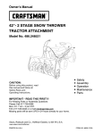
.............................
m.o- r-
Look for this symbol to point out i
tant safety
precautions,
it means
CAUTION!!!
BECOME ALERT!!!
YOUR
SAFETY
IS INVOLVED.
nu
CAUTION:
Always
disconnect
spark
plug wire and place wire where it cannot
contact spark plug in order to prevent
accidental
starting
when setting
up,
transporting,
adjusting
or making
repairs.
!
PRODUCT
CONGRATULATIONS
on your purchase of a Sears
Tractor° It has been designed, engineered and manufactured to give you the best possible dependability and
performance,,
Should you experience any problem you cannot easily
remedy, please contact your nearest Sears Authorized
Service CenteriDepartmenL
We have competent, welltrained technicians and the proper tools to service or repair
this tractor.,
Please read and retain this manual. The instructions will
enable you to assemble and maintain your tractor properly
Always observe the "SAFETY RULES'.
MODEL
NUMBER
917.252560
SPFECUFRCATIONS
HORSEPOWER:
t9..0
GASOLINE CAPACITY
AND TYPE:
3..5GALLONS
UNLEADED REGULAR
OIL TYPE (API-SFtSG);
SAE 30 (above 32°F)
SAE 5W-30 (below 32°F)
OiLcaPaciTY:
a,0P NTS
SPARK PLUG:
(GAP: ..030")
CHAMPfON RJ-19LM
STD361458
VALVE CLEARANCE:
iNTAKE:
004" - .006"
EXHAUST: .007" - 009"
GROUND SPEED (MPH):
FORWARD:
1st
2nd
3rd
4th
5th
6th
REVERSE:
SERIAL
NUMBER
DATE OF PURCHASE
THE MODELAND SERIAL NUMBERS WILL B E FOUN D
ON A PLATE UNDER THE SEAT.
YOU SHOULD RECORD BOTH SERIAL NUMBER AND
DATE OF PURCHASE AND KEEP IN A SAFE PLACE
FOR FUTURE REFERENCE.
MAINTENANCE
o
o
RESPONSIBQLITUES
Read and observe the safety rules.
Follow a regular schedule in maintaining, caring for and
using your tractor.
Follow the instructions under "Customer Responsibilities" and "Storage" sections of this owner's manual.
o
J,,L,
_"
i"
,,_,I,,i,
,
........ ,
FRONT:
REAR:
CHARGING
3 AMPS BATTERY
5 AMPS HEADLIGHTS
SYSTEM:
'
30-35 FT, LBS.
In the state of California the above is required by law
(Section 4442 of the California Public Resources Code)..
Other states may have similar laws. Federal laws apply on
federal lands. A spark arrester for the muffler is available
through your nearest Sears Authorized Service Center/
Department (See REPAIR PARTS section of this rnanual).
,:',
LIMgTED TWO YEAR WARRANTY
14 PSi
10 PSI
WARNING:
This tractor is equipped with an internal
combustion engine and should not be used on or near any
unimproved forest-covered, brush-covered or grass-covered land unless the engine's exhaust system is equipped
with a spark arrester meeting applicable local or state laws
(if any)., tf a spark arrester is used, it should be maintained
in effective working order by the operator.
A Sears Maintenance Agreement is available on this product, Contact your nearest Sears store for detaiiso
CUSTOMER
TIRE PRESSURE:
BLADE BOLT TORQUE:
AGREEMENT
1.14
150
2 34
3.50
450
&70
1..80
,,, i1"i
,,iq ........
r,....................
ON ELECTRnC START RUDING EQUmPMENT
For two (2) years from the date of purchase, if this riding equipment is maintained, lubricated and tuned up according to the
instructions in the owner's manual, Sears will repair or replace, free of charge, any parts found to be defective in matedal or
workmanship,
This Warranty does not cover:
°
°
o
°
Expendable items which become worn during normal use, such as blades, spark plugs, air cleaners and belt&
Tire replacement or repair caused by punctures from outside objects, such as nails, thorns, stumps, or glass.
Repairs necessary because of operator abuse, negligence, improper storage or accident or the failure to maintain the
equipment according to the instructions contained in the owner's manual
Riding equipment used for commercial or rental purposes.
LIMITF_.D 90 DAY WARRANTY
ON BATTERY
For ninety (90) days from date of purchase, if any battery included with this riding equipment proves defective in material or
workmanship and our testing determinesthe battery wii! not hold a charge, Sears will replace the battery at no charge.
WARRANTY SERVICE IS AVAILABLE BY RETURNING THE RIDING EQUIPMENT TO THE NEAREST SEARS SERVICE
CENTER/DEPARTMENT iN THE UNITED STATES
ThisWarranty gives you specific regalrights, and you may afso have other rights which may vary fromstate to state,
SEARS, ROEBUCK AND CQ, D/817 WA, HOFFMAN ESTATES, ILLINOIS 60179
....
,,
,
...............
3
,
r,
u
i,,, I,
i
TABLE OF CONTENTS
SAFETY RULES ............................................................
2
PRODUCT SPECIFICATIONS ......................................
3
CUSTOIVtE R RESPONSIBILITIES ..................... 3, 15-18
WARRANTY ..................................................................
3
TRACTOR ACCESSORIES ..........................................
5
ASSEMBLY .............................................................
7-10
OPERATION ..........................................................
11-14
MAINTENANCE SCHEDULE .....................................
15
SERVICE AND ADJUSTMENTS ........................... 19-24
STORAGE ...................................................................
25
TROUBLESHOOTING ...........................................
26-27
REPAIR PARTS - TRACTOR ................................ 30-47
REPAIR PARTS - ENGINE ....................................
48-53
PARTS ORDERINGISERVlCE ............... BACK COVER
NIBE×
A
E
Accessories ...................................................
5
Electrical:
Interlocks and Relays ................... 23
Schematic ............................................
29
Wiring Diagram ................................ 30
Engine:
Air Filter ............................................. 18
Air Screen ..........................................18
Cooling Fins, Engine ........................18
Oil Change ....................................... 17
Oil Level ..........................................
13,17
Oil Type ..................................................
17
Preparation ................................
13
Repair Parts .................................30-47
Starting ....................................................
14
Storage ........................................... 25
Adjustments'.
Brake ....................................................21
Carburetor ...................................... 24
Mower
Front-To-Back ........................... 20
Side-To-Side ...................................
20
Throttle Control Cable ........................
23
Air Filter, Engine ................................ 17-18
Air Screen, Engine ................................ t8
Assembly ........................................... 7-I0
B
Battery:
Charging ............................................. 8
Cleaning .................................................
17
Installation ..............................................
9
Levels ..........................................................
8,16
Preparation ...............................................
8
Starting with Weak Battery ..............
22
Storage ...................................................
25
Terminals .................................................
17
Belt:
Motion Drive
Remova!/Replacement
..............21
Mower Blade(s)
Removal/Replacement
........... 21
Blade:
Sharpening ..................................... 16
Replacement .................................... t6
Brake Adjustment .................................. 21
P
Parking Brake ................................................
12
Parts Bag .........................................................
6
Parts, Replacement!Repair .............. 30-47
Product Specifications .....................................
3
R
Repair Parts ...................................... 30-47
F
S
Filter:
Air Filter ........................................17-18
Fuel ...................................................
17-18
Fuel:
Type ........................................................
13
Storage ......................................... 25
Fuse ...................................................... 23
Safety Rules ..................................................
2
Seat .................................................................8
H
Hood Removal/Installation
.................. 23
L
Leveling Mower Deck ................................
20
Lubrication:
Chart ......................................................
15
C
M
Carburetor Adjustment ................ .......... 24
Maintenance
Schedule
.......................... 15
Controls, Tractor ................................... 11
Mower:
Customer Responsibilities ................t5-18
Adjustment, Front-to-Back ............. 20
Engine:
Air Filter .................................. 17-18
Adjustment, Side-to_Side .................
20
Blade Sharpening ............................t6
Air Screen, Engine ...................... 18
Blade Replacement ........................ 16
Cooling Fins, Engine ................. 18
Cutting Height ............................... 12
Engine Oil .................................. 17
Installation ........................................ 19
Fuel Filter ..................................... ! 8
Operation ...........................................13
Spark Plug(s) .................................18
Removal ................ _........................... 19
Tractor:
Battery ........................................................
17
Mowing Tips ............................................. 14
Blade ................................................t 6
Muffler ...................................................... 18
Lubrication Chart ........................ 15
Spark Arrester ...............................3,40
Maintenance Schedule ............ 15
Tire Care .............................. 8,16,22
Transaxle ..........................................
17
Cutting Height, Mower ...............................
12
Operation ................................................
11-14
Operating Mower .....................................13
Options:
Accessories .............................................
5
Spark Arrester ............................... 3,40
0
Oil:
Cold Weather Conditions ........ 13,17
Engine ......................................... 13,17
Storage ............................................ 25
Service and Adjustments ...................19-24
Carburetor ...............................................
24
Fuse ........................................................
23
Hood Removal/Installation ..............23
Motion Drive Belt
Removal/Replacement
...............21
Mower Belt(s)
Removal/Replacement
............ 21
Mower Adjustment
Front-to-Back ...................................
20
Side-to-Side ......................................
20
Mower Removal ....................................
19
Tire Care ......................................
8,16,22
Slope Guide Sheet ...................................55
Spark Plug(s) ........................................... t 8
Specifications ..................................................
3
Starting the Engine .............................13-14
Steering Wheel ..........................................
7,22
Stopping the Tractor ................................12
Storage ................................................................
25
T
Throttle Control Cable Adjustment ...... 23
Tires ......................................................
8,16,22
Trouble Shooting Chart ........................
26-27
Transaxte ............................................... 17
W
Warranty ........................................................3
Wiring Diagram .................................
29
-Wiring Schematic ..........................................
30
ACCESSORIES
AND ATTACHMENTS
These accessories
and attachments were available through most Sears retail outlets and service centers
Most Sears stores can order these items for you when you provide the model number of your tractor
ENGnNEE
SPARK PLUG
when the tractor was purchased
MAINTENANCE
GAS CAN
ENGINE OIL
FUEL STABILIZER
AIR FILTER
BLADES
BELTS
%
G
PERFORMANCE
Sears offers a wlde variety of attachments that fit your tractor
you. This list was current at the time of publication; however,
may be made in these attachments, or some may no longer
accessories
and attachments
that are available for your
Most of these attachments
attaching and detaching.
Many of these are listed below with brief explanations of how they can help
it may change in future years - more attachments may be added, changes
be avaifabIe or fit your model. Contact your nearest Sears store for the
tractor.
do not require additional hitches or conversion
AERATOR promotes deep root growth for a healthy lawn, Tapered 2.5-inch steel spikes mounted on 10-inch diameter discs
puncture holes in soil at close intervals to let moisture soak in..
Steel weight tray for increased penetration°
kits (those that do are indicated) and are designed for easy
SNOW BLADE for snow removal only. 14-inch high, 48-inch wide
blade clears 42-inch path when angled left or right. Raises, lowers
with side lever. Adjustable skids; replaceable, reversible scraper
bar. (Use with tire chains and wheel weights and/or rear drawbar
weight..)
BAGGER lets you collect
grass clippings and leaves for a
healthier, nearer looking lawn. Two Permanex containers hold
30-gallon plastic bags
SNOWTHROWER has 40-inch swath Drum-type auger handles
powdery and web'heavy snow. Mounts easily with simple pin
arrangement
Discharge chute adjusts from tractor seat., 6-inch
diameter spout discharges snow 10 to 50 feet. Lift controlled at
tractor seat. (Use with chains and wheel weights and/or rear
drawbar weight..)
SPRAYERS use 12-volt DC electric motor that connects to the
tractor battery or other 12-volt source.. Includes booms for
automatic spraying and hand held wand for spot spraying, Wand
has adjustable spray pattern° For applying herbicides, insectF
cides, fungicides and Iiquid fertilizers
SPREADER/SEEDERS
make seeding, fertilizing, and weed killing easy. Broadcast spreaders are also useful for granular deicers and sand.
BUMPER protects front end of tractor from damage
CARTS make hauling easy. Variety of sizes available, plus
accessories such as side panel kits, tool caddy, cart cover,
protective mat and dolly
CORING AERATOR takes small plugs out of soil to allow moisture and nutrients to reach grass roots. 364nch swath. 24
hardened steel coring tips. 150 Ib capacity weight tray
EASY OIL DRAIN VALVE makes oil changes easier, faster..
FRONT NOSE ROLLER canters in front of mower deck to reduce
chances of "scalping" on uneven terrain,
GANG HITCH lets you tow 2 or3 pull-behind attachments at once,
such as sweepers, dethatchers, aerators (not for use with rollers,
carts or other heavy attachments)
GAUGE WHEELS on both sides of the mower deck reduce
chances of "scalping" on uneven terrain For mower decks not so
equipped.
MULCH RAKFJDETHATOHER loosens soil and flips thatch and
matted leaves to lawn surface for easy pickup.. Twenty spring fine
teeth, Useful to prepare bare areas foreeeding. Available for front
or rear mounting.
HIGH PERFORMANCE
REEL-ACTtON
SPRING TINE DETHATCHER covers 364nch wide path and
tosses thatch into large hopper. Mounts behind tractor,
SWEEPERS let you collect grass clippings and leaves.
TILLER has 5 hp engine and 36-inch swath to prepare seed beds,
cultivate and compost garden residue,r Tiller has its own built-in
lift and depth control system and does NOT require a sleeve hitch..
Fits any lawn, yard or garden tractor. Simply hook up to the tractor
drawbar and go! Optional
accessories
convert unit for
dethatching, aerating, hilling., .without tools.
TIRE CHAINS are heavy duty; closely spaced extra-large cross
links give smooth ride, outstanding traction_
TRACTOR CAB has heavy duty vinyl fabric over tubular steel
frame, ABS plastic top; clear plastic windshield offers 360 degree
visibility. Hinged metal doors with catch. Keepsoperatorwarm
and dry. Remove vinyl sides and windshields for use as sun
protector in summer. Optional accessories
include:
tinted/
tempered solid safety glass windshield with hand operated wiper;
12-volt amber caution light for mounting on cab top.
VACS for powerful collection of heavy grass clippings and leaves,,
Optional wand attachment to pick up debris in hard-to-reach
places° VAC/CH1PPER includes a chipper-shredder.
WEIGHT BRACKET for drawbar for snow removal applications.
Uses (1) 55 Ib weight,.
WHEEL WEIGHTS for rear wheels provide needed traction for
snow removal or dozing heavy materials.
MULCHING CLOSE*OUT PLATE KIT, once installed, lets you
mulch, discharge or bag clippings (bagger optional) without
changing blades. For models not equipped as 3-in-1 Convertible
mowers.
See "MOWER" in the Repair Parts section of this
manual.
RAMP TOPS AND FEET let you load and unload tractor from a
pickup truck.. Use with 2 x 8 or 2 x I0 lumber.
ROLLER for smoother lawn surface.
36-inch wide, 184nch
diameterwater-tight
drum holds up to 390 Ibs of weight° Rounded
edges prevent harm to turf, Adjustable scraper automatically
cleans drum.
5
,,,i,,,u,
,,
..............................
CONTENTS
....
i
, .............
................ ..:.
,.......
,
.............................
OF HARDWARE
,,,,,..............
i
,
.... i,,
shown full size
,,
i
,
,
,..............
,
Parts packed separately
in carton
,i........
lU................
Seat
©
,,
PACK
......
i,,,
Parts Bag contents
, ,,, ........
Mulcher
Plate
(2) Sheet
Metal
Screws
#10-16 x 1/2
Battep2 acid
Steering Wheel
(1) Locknut 3/8-24
(1) Large Flat Washer
....... i ...........
U
Steering
Boot
Ill,,,,
Parts Bag
(1) Shoulder Bott 5/16-18
(1) Hex Boft 1/2-13 x 1
,,
Owner's Manual
'.......
i ........
i,
, ............
,
Parts bag contents not shown
//_1
(2) Shoulder
Bolts
(t) Washer 17/32 x 1-3/16 x 12 Gauge
......
o
(2) Screws #10 x 5/8
(2) Lock Washers #10
(_-_
"_==j/(2)
(2) Gauge
Wheels
\_iJ
(2) Washers 3/8
x 7/8 x 14 Gauge
Wheel
Steering
Adapter
__
@
_
Nuts
(2)lock
Center-
(2) Keys
Bushing
teering
<2)
_Ve,d
Nuts
_1o
_
SteerlnngeV_/heel
Washers 3/16 x 3/4 x t6 Gauge
(2) Hex Bolts 1/4-20 x 3/4
@
®
Assemblys
• ,3 .........
(2) Washers 9t32 x 5t8 x 16 Gauge
(2) Lock Washers 1/4
,*
i
i--
(2) Hex Nuts 1/4-20
I
.........
15° Slope Sheet
.....
full size
[,
Battery Caps
and Instructions
ASSEMBLY
.... r
,i,
,,,i ...........
,,
,i .....
lU.........
i,
i,,,i
........
Your new tractor has been assembled at the factory with exception of those parts left unassembled for shipping purposes,
To ensure safe and proper operation of your tractor, all parts and hardware you assemble must be tightened securely° Use
the correct tools as necessary to insure proper tightness.
TOOLS
REQUIRED
FOR ASSEMBLY
/---.._.______mSERT
A socket wrench set wilt make assembly easier. Standard
wrench sizes are listed°
(!)
5/16" wrench
(1) 9/16" wrench
(2) 7/16" wrenches
(1) Phillips screwdriver
(1) 1/2" wrench
Utility knife
(1) 3/4" wrench
Tire pressure gauge
=_
When right and left hand is mentioned in this manual, it
means when you are in the operating position (seated
behind the steering wheel).
STEERING
TO REMOVE TRACTOR FROM CARTON
Remove all accessible loose parts and parts cartons
from carton (See page 6)_
•
Cut, from top to bottom, along lines on all four corners
of carton, and lay panels flat.
=
Check for any additional
remove,
STEERING
2
WHEEL
#.%
TABS
BOOT
POSITION)
_
STEERING
(SHIPPING
POSITION)
SHAFT
,,
TAB SLOT
loose parts or cartons and
FIG. 1
BEFORE ROLUNG TRACTOR OFF SKID
ATTACH
STEERING
STEERING SHAFT
(ASSEMBLY
CARTON
o
_
STEER,NG
(1) 3/4" socket with drive ratchet
UNPACK
,
WHEEL (See Fig. 1)
TO ROLL TRACTOR
OFF SKiD (See Fig. 7)
=
Slide the steering bushing over the steering shaft.
o
Raise attachment lift lever to its highest position,
o
Raise steering shaft forward until screw holes in dash
line up with steering bushing. Install two (2) sheet
metal screws and tighten securely.
o
o
Position steering boot over steering shaft.
•
°
Release parking brake by depressing clutchlbrake
pedal,,
Place gearshift lever in neutral (N) position.
Roll tractor backwards off skid.
o
Place tabs of steering boot over tab slots in dash and
push down to secure°
o
•
Slide steering wheel adapter onto upper steering shafL
•
Position front wheels of the tractor so they are pointing
straight forward.
o
Position steering wheel so cross bars are horizontal
(left to right) and slide onto adapter.
o
Assemble large flat washer and 3/8-24 Iocknut and
tighten securely,,
=
Snap steering wheel insert into center of steering
wheel.
= Remove protective plastic from tractor hood and grill.
IMPORTANT:CHECK FOR AND REMOVE ANY STAPLES
IN SKID THAT MAY PUNCTURE TIRES WHERE TRACTOR
IS TO ROLL OFF SKID
7
Remove banding holding discharge guard up against
tractor.
i,,, ,,,, ,,u,
................
'
ASSEMBLY
HOW TO SET UP YOUR TRACTOR
PREPARE
BATTERY
TERMINAL
GUARD
(See Figs, 2A and 2B)
Wash hands or clothing immediately if
accidentally in contactwith battery acid,
Do not smoke. Fumes from charged
battery acid are explosive.
Read the instructions included with the
battery vent caps, Always wear gloves,
clothing and goggles to protect your
hands, skin and eyes.
:°
BATTERY
BOLTS
Your tractor has a battery charging system which is sufficient for normal use° However, periodic charging of the
battery with an automotive charger will extend its life
o See instructions packed with vent caps in parts bag.
o Lift hood to raised position.
o
Remove battery from tractor to fit! with acid and charge.,
To remove battery, remove terminal guard and battery
bolts securing battery to tractor.
•
Fill battery with acid, Fill each cell until it reaches the
bottom of the vent wells.. Do not overfi]t.
o Allow battery to stand and settle for at least thirty
minutes. After standing, check the battery ceil acid
level If below the vent wells, add more acid until the
correct level is reached.
FIG. 2A
CUT AWAY VIEW
o
o
o
VENT CAP
_.,,
BATTERY
FIG. 2B
While battery is standing (after adding acid) and Pater,while
battery is being charged, continue with assembly of tractor.
IMPORTANT;
TO MAXIMIZE THE LIFE OF YOUR
BATTERY, IT IS NECESSARY THAT THE BATTERY BE
CHARGED BEFORE USE. FAILURE TO CHARGE
BATTERY CAN RESULT IN A SHORTENED BATTERY
LIFE,,
•
Charge battery at a rate of 6 amperes for I hour° Use
a 12 volt battery charger, Observe all safety precautions required for battery charging,
.
Check the acid level after the battery is charged, if the
acid has fallen below the correct level, add distilled or
iron free water.
o
S
INSTALL
SEAT (See Fig. 3)
Adjust seat before tightening adjustment bolt.
Install the vent caps to cover the vent weIIs., Wash the
top of the battery with water to remove any acid, then
wipe dry_
Check battery case for leakage to make sure that no
damage has occurred in handling.
Dispose of excess battery acid. Neutralize acid for
disposal by adding it to two gallons of water in a five
gallon plastic container. Stir with a wooden or plastic
paddle while adding baking soda until the addition of
more soda causes no more foaming,,
Follow instructions on how to install battery.
°
Remove cardboard packing on seat pan_
=
Place seat on seat pan and assemble shoulder boll
o
Assemble adjustment bolt, lock washer and flat washer
loosely., Do not tighten.
•
Tighten shoulder bott securely.
=
Lower seat into operating position and sit on seat.
o
Slide seat until a comfortable position is reached which
allows you to press clutch/brake pedal all the way
down.
o
Get off seat without moving its adjusted position.
o
Raise seat andtighten
adjustment bolt securely°
SEAT
SEAT PAN
SHOULDER
BOLT
\
LARGE FLAT
WASHER
ADJUSTMENT
BOLT
8
LOCK WASHER
FIG. 3
===t====t_.--._.......
i
......... ,.....
AG,GEMBLY
......
i
CHECK
';''
TiRE PRESSURE
The tires on your tractor were overinflated at the factory for
shipping purposes Correct tire pressure is important for
best cutting performance.
o
Reduce tire pressure to PSI shown in "PRODUCT
SPECIFICATIONS" on page 3 of this manual
CHECK
DECK LEVELNESS
THREADED
FOR
PROPER
POSITION
,,,,
DRAIN TUBE
(See Figs. 4A and 4B)
HEX BOLT
NEGATIVE
{BLACK)
CABLE
,,,
FIG. 4B
ASSEMBLE
GAUGE
WHEELS
TO
MOWER
DECK (See Fig. 5)
Assemble gauge wheels with tractor on a flat level surface.
Lift hood to raised position.
Be sure battery drain tube has not come loose and is
securely attached to drain in battery tray.
Lower battery into battery tray with terminals to front of
tractor,
Inspection for secure connections
ware).
Inspection for corrosion.
Testing battery..
Jumping (if required),
Periodic charging..
FLAT WASHER
POSITIVE
(RED)
CABLE
Position terminal guard over battery and install battery
bolts through guard mounting holes and into threaded
fasteners on support plate.
o Tighten battery bolts securely, but do not over tighten.
o Open terminal access doors,
o
First connect RED battery cable to positive (+)battery
terminal with hex bolt, ftat washer, lock washer and hex
nut as shown. Tighten securely.
°
Connect BLACK grounding cable to negative (-) battery
terminal with remaining hex bolt, flat washer, lock
washer and hex nut. Tighten securely.
o Close terminal access doors.
Use terminal access doors for:
o
.
•
TRAY
TERMINAL
ACCESS
DOOR
o
Adjust mowerto desired cutting height (See ''TO ADJUST MOWER CUTTING HEIGHT' in the Operation
section of this manual)°
o
With mower in desired height of cut position, gauge
wheels should be assembled so they are slightly off the
ground. Install gauge wheel in appropriate hole with
shoulder bolt, 3/8 washer and 3/8-16 Iocknut and
tighten securely°
Repeat for opposite side installing gauge wheel in
same adjustment hole.
o
o
BATTERY
HEX NUT
,,i,iii .................
•
_
LOCK
WASHER
CAUTION: Do not short battery terminals. Before installing battery, remove
metal bracelets,
wristwatch bands,
rings, etc.
Positive terminal must be connected
first to prevent sparking from accidental grounding."
•
=
GUARD
FIG. 4A
After you learn how to operate your tractor, check to see
that the brake is properly adjusted. See "TO ADJUST
BRAKE" in the Service and Adjustments section of this
manual
BATTERY
_/./_"_
OF ALL
CHECK BRAKE SYSTEM
.......
_"°
\_._'
See the figures that are shown for replacing motion and
mower bfade drive belts in the Service and Adjustments
section of this manual
Verify that the belts are routed
correctly.
INSTALL
""°..,._._._.:
.,._"
__lJ
For best cutting results, mower housing should be properly
leveled_ See '`TO LEVEL MOWER HOUSING" in the
Service and Adjustments section of this manual.
CH_CK
BELTS
•s
o
GAUGE WHEEL
MOUNTING
BRACKET
(to tighten hardLOCKNUT
318 WASHER
SHOULDER
GAUGE WHEEL"
FIG. 5
9
BOLT
.................
i,,_r
..............................................................
ASSE#BLY
iNSTALL MULCHER
(See Figs. 6A & 68)
o
PLATE
DEFLECTOR
SHIELD
Install two latch hooks to mutcher plate using screw,
washer, lock washer, and weld nut as shown.
NOTE: Pre-assembte weld nut to latch hook by inserting
weld nut from the top with hook pointing down.
o
Tighten hardware securety_
o
Raise and hold deflector shield in upright position..
=
•
Place front of mulcher plate over front of mower deck
opening and slide into place, as shown.
Hook front latch into hole on front of mower deck
•
Hook rear latch into hole on back of mower deck_
_i
cAUTION: DO not remove discharge ..... i
guard from mower. Raise and hold
i
guard when attaching mulcher plate
R
and allow it to rest on plate while in
_,
! t
opera tion.
TO CONVERT
DISCHARGING
HOOKS
FiG. 6B
_____._j
TO BAGGaNG
OR
J CHECKLIST
BEFORE YOU OPERATE AND ENJOY YOUR NEW
TRACTOR, WE WISH TO ASSURE THAT YOU RECEIVE
THE BEST PERFORMANCE AND SA TISFA CTION FROM
THIS QUALITY PRODUCT
Simply remove mulcher plate and store in a safe place,
Your mower is now ready for discharging or installation of
optional grass catcher accessory
PLEASE REVIEW THE FOLLOWING
HOOK POINTS
DOWN
WELD NUT
CHECKLIST:
V" All assembly instructions have been complete&
v" No remaining loose parts in carton.
,/" Battery is properly prepared and charged°
1 hour at 6 amps).
(Minimum
LOCK
,/
WELD.
NUT
_
WASHER
Seat is adjusted comfortably and tightened securely
v" All tires are properly inflated. (For shipping purposes,
the tires were overinflated at the factory)_
,/
LATCH
HOOK
HOOK
Be sure mower deck is properly leveled side-to-side!
front-to-rear for best cutting results. (Tires must be
properly inflated for leveling).
_," Check mower and drive belts. Be sure they are routed
properly around pulleys and inside all belt keepers.
LOCK
WASHER
WASHER
•/
WELD
NUT
Check wiringo See that all connections are still secure
and wires are propedy clamped.
WHILE LEARNING HOWTO USE YOUR TRACTOR, PAY
EXTRA ATTENTION TO THE FOLLOWING IMPORTANT
ITEMS:
WASHER
MULCHER
PLATE
FiG. 6A
10
,/
Engine oil is at proper level°
,/
Fuel tank is filled with fresh, clean, regular unleaded
gasoline
,/
Become familiar with all controts - their location and
function. Operate them before you start the engine.
,/
Be sure brake system is in safe operating condition.
il
OPERATBON
KNOW YOUR TRACTOR
READ THUS OWNER'S
MANUAL
AND SAFETY
RULES
BEFORE
OPERATING
YOUR
TRACTOR
Comparethe illustrationswith your tractor to familiarize yourself with the locations of various controls and adjustments_ Save
this manual for future reference,
ATTACHMENTCLUTCHLEVER
LIFT LEVER
PLUNGER
AMMETER
IGNITION
SWITCH
CHOKE
LIGHT SWITCH
]
ATTACHMENT
LIFT LEVER
CLUTCH/BRAKE
PEDAL
PARKING
BRAKE LEVER
THROTTLE
CONTROL
HEIGHT
ADJUSTMENT
KNOB
.GEARSHIFT
LEVER
FIG. 7
Our tractors conform to the safety standards of the American National Standards Institute,
THROTTLE CONTROL: Used for starting and controlling
engine speed°
CHOKE CONTROL: Used for starting a cold engine.
ATTACHMENT CLUTCH LEVER: Used to engage the
mower blades, or other attachments mounted to your
tractor.
LIFT LEVER PLUNGER: Used to release attachment lift
CLUTCHIBRAKE PEDAL: Used for clutching and braking
the tractor and starting the engine°
HEIGHT ADJUSTMENT
cutting height.
lever when changing its position°
ATTACHMENT LIFT LEVER: Used to raise and lower the
KNOB: Used to adjust the mower
mower deck or other attachments mounted to your tractor,
PARKING BRAKE LEVER: Locks Clutch/Brake Pedal into
the brake position,
IGNITION SWITCH: Used for starting and stopping the
engine.
LIGHT SWITCH: Turns the headlights on and off_
AMMETER:
battery°
GEARSHIFT
tractor.
Indicates charging (+) or discharging (-) of
11
LEVER: Selects the speed and direction of
OPERATION
........
,,,,,,,,
,, ,,,,,,
,, ........................
, .........
The operation of any tractor can result in foreign objects thrown into the eyes, which
can result in severe eye damage. Always wear safety glasses or eye shields while
operating your tractor or performing any adjustments or repairs, We recommend a
wide vision safety mask over the spectacles or standard safety glasses,
HOW TO USE YOUR TRACTOR
TO MOVE FORWARD
(See Fig, 8)
TO SET PARKING
The direction and speed of movement is controlled by the
gearshift lever,
•
Start tractor with clutch!brake pedal depressed and
gearshift lever in neutral (N) position.
o Move gearshift lever to desired position.
= Slowly release clutch/brake pedal to start movement.,
IMPORTANT: BRING TRACTOR TO A COMPLETE STOP
BEFORE SHIFTING OR CHANGING GEARS. FAILURE
TO DO SO WILL SHORTEN THE USEFUL LIFE OF YOUR
TRANSAXLE.,
BRAKE
(See Fig. 8)
Your tractor is equipped with an operator presence sensing
switch,, When engine is running, any attempt by the
operator to leave the seat without first setting the parking
brake will shut off the engine.
o Depress clutch/brake pedal into full "BRAKE" position
and hold.
o
Place parking brake lever in "ENGAGED" position and
release pressure from clutch/brake pedat. Pedal should
remain in "BRAKE" position. Make sure parking brake
will hold tractor secure._
STOPPING
AT_'ACHMENT CLUTCH
"ENGAGED" POSITION
(See Fig. 8)
MOWER BLADES o
Move attachment clutch lever to "DISENGAGED"
sition
GROUND DRIVE -
CHOKE
CONTROL
po-
CLUTCHIBRAKE
PEDAL"DRIVE"
POSITION
BRAKE
POSITION
GEARSHIFT
LEVER
HEIGHT
ADJUSTMENT
FIG. 8
TO ADJUST MOWER
(See Fig. 8)
CAUTION:
Always stop tractor completely, as described above, before leaving the operator's position; to empty
grass catcher, etc.
CUTTING
HEIGHT
The cutting height is controlled by turning the height adjustment knob in desired direction.
(See Fig. 8)
Always operate engine at futl throttle.
o Operating engine at less than fult throttle reduces the
battery charging rate.
o Full throttle offers the best bagging and mower performance.
CONTROL
"DISENGAGED"
POSITION
PARKING
o Never use choke to stop engine.
NOTE: Under certain conditions when tractor is standing
idle with the engine running, hot engine exhaust gases may
cause "browning" of grass, To eliminate this possibility,
always stop engine when stopping tractor on grass areas,
TO USE CHOKE
IGNITION KEY
"BRAKE"
POSITION
.
Move throttle control to slow (_)
position.
NOTE:
Failure to move throttle control to slow (_)
position and atlowing engine to idle before stopping may
cause engine to "backfire".
•
Turn ignition key to "OFF" position and remove key.
Always remove key when leaving tractor to prevent
unauthorized use.,
CONTROL
LEVER
THROTTLE
CONTROL
o Depress clutch/brake pedal into fuft "BRAKE" position,
•
Move gearshift lever to neutral (N) position°
ENGINE -
TO USE THROTTLE
AND BACKWARD
(See Fig. 8)
Use choke control whenever you are starting a cold engine,
Do not use to start a warm engine°
o To engage choke control, pull knob out. Slowly push
knob in to disengage,
12
o
Turn knob clockwise ((_)
o
Turn knob
height.
to raise cutting height.
counterclockwise
(_---_)to
lower cutting
The cutting height range is approximately 1-1/2" to 4". The
heights are measured from the ground to the blade tip with
the engine not running. These heights are approximate
and may vary depending upon soil conditions, height of
grass and types of grass being mowed.
o The average lawn should be cut to approximately 2-1/2
inches during the cool season and to over 3 inches
during hot months. For heatthier and better looking
lawns, mow often and after moderate growth.
o For best cutting performance, grass over 6 inches in
height should be mowed twice. Make the first cut
relatively high; the second to desired height.
OPERATION
TO OPERATE
MOWER
(See Fig. 9)
Your tractor is equipped with an operator presence sensing
switch. Any attempt by the operator to leave the seat with
the engine running and the attachment clutch engaged will
shut off the engine,
•
Select desired height of cut
=
Lower mower with attachment lift control.
o
Start mower blades by engaging attachment
control°
,
TO STOP MOWER BLADES - disengage attachment
clutch controt.
Move gearshift lever to 1st gear. Be sure you have
allowed room for tractor to roll slightly as you restart
movement.
o
To restart movement, slowly release parking brake and
clutch/brake pedal.
o
Make all turns slowly,
TO TRANSPORT
clutch
CAUTION: Do not operate the mower
without either the entire grass catcher,
on mowers so equipped, or the discharge guard in place.
ATTACHMENT
CLUTCH LEVER
"DISENGAGED"
POSITION
°
,,
Raise attachment lift to highest position with attach_
ment lift control
°
When pushing or towing your tractor, be sure gearshift
lever is in neutral (N) position.
o
Do not push or tow tractor at more than five (5) MPHo
NOTE: To protect hood from damage when transporting
your tractor on a truck or a trailer, be sure hood is closed
and secured to tractor.. Use an appropriate means of tying
hood to tractor (rope, cord, etc.)o
ATTACHMENT CLUTCH LEVER
"ENGAGED"
POSITION
BEFORE
LIFT LEVER
"HIGHEST"
CHECK
LOWEST
POSITION
STARTING
ENGINE
THE ENGINE
OIL LEVEL (See Fig. 15)
=
The engine in your tractor has been shipped, from the
factory, already filled with summer weight oil
=
Check engine oit with tractor on level ground.
o
Remove oil fit lcap/dipstick and wipe clean, reinsert the
dipstick and screw cap tight, wait for a few seconds,
remove and read oil level If necessary, add oil until
"FULL" mark on dipstick is reached, Do not overfill.
•
For cold weather operation you should change oil for
easier starting (See "OIL VISCOSITY CHART" in the
Customer Responsibilities section of this manual).
o
To change engine oil, see the Customer ResponsibitF
ties section in this manual.
ADD GASOLINE
o
Fitl fuel tank. Use fresh, clean, regular unleaded
gasoline. (Use of leaded gasolinewiil increase carbon
and lead oxide deposits and reduce vafve life).
IMPORTANT: WHEN OPERATING IN TEMPERATURES
BELOW 32°F(0°C), USE FRESH, CLEAN WINTER GRADE
GASOLINE TO HELP INSURE GOOD COLD WEATHER
STARTING.
DISCHARGE
GUARD
FIG. 9
TO OPERATE
I
,_
WARNING:
Experience indicates that alcohol blended
fuels (calted gasohol or using ethanol or methanol) can
attract moisture which Ieads to separation and formation of
acids during storage. Acidic gas can damage the fuel
system of an engine while in storage. To avoid engine
problems, the fuel system should be emptied before storage of 30 days or Ionger. Drain the gas tank, start the
engine and let it run until the fuel lines and carburetor are
empty. Use fresh fuel next season. See Storage Instructions for additional information.
Never use engine or
carburetor cleaner products in the fuel tank or permanent
damage may occur°
ON HILLS
hills with slopes greater than 15° and
CAUTION:
not drive
up or down
do not drive Do
across
any slope.
•
Choose the slowest speed before starting up or down
hills.
•
Avoid stopping or changing speed on hills°
o
If slowing is necessary, move throttle control lever to
slower position,,
o
If stopping is absolutely necessary, push clutch/brake
_edal quickly to brake position and engage parking
rake.
=
13
: :1 ,i i,
filler
neck. Do
offany
CAUTION:
FillnotoverfilL
to bottom Wipe
of gas
tank
spilled oil or fuel. Do not store, spill or
II
I
use gasoline
I
i i
, m u
near an open flame.
i ..............................
OPEIRATUO
TO START
ENGINE
(See Fig. 8)
°
When starting engine for the first time or if engine has run
out of fuel, it will take extra cranking time to move fuel from
the tank to the engine
o
Depress clutch/brake pedal and set parking brake
o
Place gearshift lever in neutral (N) position.
•
Move attachment clutch to "DISENGAGED"
°
Pull choke control out to choke (N) position for cold
engine start. For warm engine start do not use choke
control..
•
Move throttle control to midway between fast (,t_) and
slow (,_) positions.
o
When operating attachments, select a ground speed
that will suit the terrain and give best performance of
the attachment being used
f
position.
Insert key into ignition and turn key clockwise to"START"
position and release key as soon as engine starts. Do
not run starter continuously for more than fifteen
seconds per minute,. If engine does not start after
several attempts, move throttle control to fast (._,)
position, wait a few minutes and try again,
FIG, 10
o
When engine starts, slowly push choke control in..
MULCHING
.
Move throttle control to fast (.f_) position
•
Allow engine to warm up for a few minutes before
engaging drive or attachments,.
IMPORTANT:
FOR BEST PERFORMANCE,
KEEP
MOWER HOUSING FREE OF BUILT-UP GRASS AND
TRASH CLEAN AFTER EACH USE,
NOTE: If at a high altitude (above 3000 feet) or in cold
temperatures (below 32°F), the carburetor fuel mixture
may need to be adjusted for best engine performance. See
"TO ADJUST CARBURETOR" in the Service and Adjustments section of this manual.
Tire chains cannot be used when the mower housing
is attached to tractor.
.
Mower should be properly leveled for best mowing
performance. See "TO LEVEL MOWER HOUSING" in
the Service and Adjustments section of this manual.
The left hand side of mower should be used for trimming,
.
o
The special mulching blade will recut the grass clippings many times and reduce them in size so that as
they fall onto the lawn they will disperse into the grass
and not be noticed
Also, the mulched grass wilt
biodegrade quickly to provide nutrients for the lawn.
Always mulch with your highest engine (blade) speed
as this will provide the best recurring action of the
blades
-
Avoid cutting your lawn when it is wet. Wet grass tends
to form clumps and interferes with the mulching action.
The best time to mow your lawn is the early afternoon.
At this time the grass has dried and the newly cut area
will not be exposed to the direct sun,
o
For best results, adjust the mower cutting height so that
the mower cuts off only the top one-third of the grass
blades (See Fig. 11).. For extremely heavy mulching,
reduce your width of cut on each pass and mow slowly.
Drive so that clippings are discharged onto the area
that has been cut. Have the cut area to the right of the
machine. This will result in _amore even distribution of
clippings and more uniform cutting..
-
When mowing large areas, start by turning to the right
so that clippings will discharge away from shrubs,
fences, driveways, etc,. After one or two rounds, mow
in the opposite direction making left hand turns until
finished (See Fig 10 )4
o
If grass is extremely tall, it should be mowed twice to
reduce load and possible fire hazard from dried clippings° Make first cut relatively high; the second to the
desired height°
o
Do not mow grass when it is wet. Wet grass will plug
mower and leave undesirable clumps. Allow grass to
dry before mowing,.
°
TIPS
o
MOWING TIPS
=
MOWING
MAX 1/3
FIG. 1 !
Always operate engine at full throttle when mowing to
assure better mowing performance and proper discharge of material, Regulate ground speed by selecting a low enough gear to give the mower cutting
performance as well as the quality of cut desired_
14
o
Certain types of grass and grass conditions may require that an area be mulched a second time to
completely hide the clippings. When doing a second
cut, mow across or perpendicular to the first cut path,
•
Change your cutting pattern from week to week. Mow
north to south one week then change to east to west the
next week. This will help prevent matting and graining
of the lawn,.
MAINTENANCE
SCHEDULE
FILL IN DATES
__£J
AS YOU COMPLETE
REGULAR
SERVICE
__,_SE__R
.......... ,,,,
Check
Check
R
Brake Operation
Pressu;e
forLoose Fasteners
"Sharpen/Repl'a'ce
',5_ _,..,_vj
_
_#_
_
_'
................t_
Clean Batteryand
R
Check Transaxle
_
_
.......................
6/'
' e"
I=
....
64#s
6_
E €leanAi;Fi'lter.......
N
.......... V'
,,
¢*
,
.
.
i
--
................
64_'2 ...............
Arrester
_1'
6_I,2
Clean"Engine
_'2
Fins
Replace
Spark Plug
6/
Replace
Air Filler Paper Cartridge
6/'2
Replace
Fuel Filter
,,1 ..................
5 - if equipped with adjustable system
6 - Not requited if equipped with maietenance-lree battery
7 - Tighten front axle pivot boll to 35 It 4bs maximum
Do r_etovertlghten
LUBRICATION
RECOMMENDATIONS
The warranty on this tractor does not cover items that have
been subjected to operator abuse or negligence.
To
receive full value from the warranty, operator must maintain
tractor as instructed in this manual
......
6/'
1 - Change more often when operating under a heavy ;cad or in high ambient temperatures
2 - Service more often when operating in dirty Ot dusty conditions
3 - If equipped with oil filter, change oil avery 50 hours
4 - Replace blades more olten when mowing t_ sandy soil
GENERAL
, ......................
Replace"'(_i[
Filter (if equipped)
Cooling
........
_4'
..............
I
Engine
Level
Change
EngOilneOii
Inspect Muffler/Spark
"
_
_'s
Check
t
,
l
_
Adjust Mq,tion,,,Drive Belt,(s) Tension
G
.........
_
Terminals
Coot!rig
p"
6/
.....................
,C lean Air Screen
_,J
$##4
Adjust Blade Be]t(Si"T'ension
N
_._
,,,
_/7
Mower Blades
Ch__eck Battery Level/Recharge
0
.{'.
VtCE DATES
,
Lub;i'ca'iion Chart
cA
O
_,_,
Check"-Fire
T
.'o"
CHART
PINDLE ZERK (_)
(_) SPI
(_
BEARING
_ FRONT WHEEL (_)
BEARING ZERK
ZERK
Some adjustments will need to be made periodically to
properly maintain your tractor
ENGINE (_)
All adjustments in the Service and Adjustments section of
this manual should be checked at least once each season.
o
C
Once a year you should replace the spark plug, clean
or replace air filter, and check blades and belts for
wear,. A new spark plug and clean air filter assure
proper air-fuel mixture and help your engine run better
and last longer..
BEFORE
EACH
CLUTCH
PIVOT{S)
USE
•
Check engine oil level.
,
Check brake operation
o
-
Check tire pressure.
Check for loose fasteners.
(_) SAE 30 OR 10W30 MOTOR OIL
(_) GENERAL
I_
PURPOSE GREASE
REFER TO CUSTOMER
RESPONSIBILITIES
"ENGINE"
SECTION
IMPORTANT:
DO NOT OIL OR GREASE THE PIVOT POINTS
WHICH HAVE SPECIAL NYLON BEARINGS
VISCOUS LUBRICANTS WILL ATTRACT
DUST AND DIRT THAT WILL SHORTEN
THE LIFE OF THE SELF-LUBRICATING
BEARINGS.
tF YOU
FEEL THEY MUST BE LUBRICATED,
USE ONLY A DRY, POW.,
DERED GRAPHITE
TYPE LUBRICANT
SPARINGLY
15
CUSTOMER
RESPONSIBILITIES
TRACTOR
TO SHARPEN
Always observe safety rules when performing any maintenance,
Care should be taken to keep the blade balanced. An
unbalanced blade will cause excessive vibralon and eventuat damage to mower and engine.
BRAKE
.
The blade can be sharpened with a file or on a grinding
wheel. Do not attempt to sharpen while on the mower.
.
To check blade balance, you wii need a 5/8" diameter
steei bolt, pin, or a cone balancer (When using a cone
balancer, fotow the instructions supplied with baF
OPERATION
If tractor requires more than six (6) feet stopping distance
at high speed in highest gear, then brake must be adjusted
(See "TO ADJUST BRAKE" in the Service and Adjustments section of this manual).
BLADE
(See Fig. 13)
ancer),
TIRES
°
o
Maintain proper air pressure in all tires (See "PROD*
UCT SPECIFICATIONS" on page 3 of this manual).
.
Keep tires free of gasoline, oit, or insect control chemicals which can harm rubber.
=
Avoid stumps, stones, deep ruts, sharp objects and
other hazards that may cause tire damage.
BLADE
Slide blade on to an unthreaded portion of the steel bolt
or pin and hold the bolt or pin parallel with the ground,
If blade is balanced, it should remain in a horizontal
position, tf either end of the blade moves downward,
sharpen the heavy end until the blade is balanced.
NOTE: Do not use a nail for balancing blade., The lobes of
the center hole may appear to be centered, but are not.
CARE
j'
/
For best results mower blades must be kept sharp.. Replace bent or damaged blades.
BLADE
REMOVAL
I
>
/
(See Fig. 12)
•
Raise mower to highest position to allow access to
blades.
°
Remove hex bolt, Iock washer and fiat washer securing
blade.
o
Install new or resharpened blade with trailing edge up
towards deck as shown,
,
Reassemble hex bolt, lock washer and flat washer in
exact order as shown.
eta' BOLT.J
"_k.l/',_
OR PIN
_
FIG. 13
BATTERY
(See Fig. 14)
Tighten bolt securely (30-35 Ft, Lbs. torque).
IMPORTANT: BLADE BOLT 1SGRADE 8 HEATTREATED
Your tractor has a battery charging system which is sufficient for normal use. However, periodic charging of the
battery with an automotive charger will extend its life.
NOTE: We do not recommend sharpening blade * but if you
do, be sure the blade is balanced_
=
Acid solution level in each battery cell should be even
with bottoms of vent wells. Add only distilled or iron free
water if necessary. Do not overfill,
MANDREL
,
Keep battery and terminals clean,
ASSEMBLY
,
Keep battery bolts tight°
•
Keep vent caps tight and small vent holes in caps open.
o
Recharge at 6 amperes for I hour.
----_
__
CUT AWAY VIEW
VENT CAP
VENT
WELL
BATTERY
CELL ACID
LEVEL
*A GRADE 8 HEAT TREATED BOLT CAN BE IDENTIFIED
BY SIX LINES ON THE BOLT HEAD.
FIG. 12
FIG. 14
16
CUSYOME
RESPONSUBIUVIES
TO CLEAN BATTERY AND TERMINALS
o
Corrosion and dirt on the battery and terminals can cause
the battery to "leak" power+
= Remove terminal guard,
•
Disconnect BLACK battery cable first
then RED
battery cable and remove battery from tractor,,
',
Wash battery with solution of four tablespoons of
baking soda to one gallon of water. Be careful not to
get the soda solution into the cells,,
Rinse the battery with plain water and dry,
.
Clean terminals and battery cable ends with wire
brush until bright°
= Coat terminals with grease or petroleum jelly
= Reinstall battery (See "INSTALL BATTERY" in the
Assembly section of this manual),,
o
.
After oil has drained completely, replace oil drain plug
and tighten securely.
Refill engine with oit through oil fill dipstick tube. Pour
slowly. Do not overfill For approximate capacity see
"PRODUCT SPECIFICATIONS"
on page 3 of this
manual
Use gauge on oil flit dipstick for checking level Be sure
dipstick cap is tightened securely for accurate reading+
Keep oil at "FULL" tire on dipstick,,
V-BELTS
Check V-betts for dete rioration and wear after 100 hours of
operation and replace if necessary. The belts are not
adjustable. Replace belts if they begin to slip from wear.
TRANSAXLE
COOLING
Keep transaxle free from build-up of dirt and chaff which
can restrict cooting_
FIG. 15
ENGINE
LUBRICATION
CLEAN
Only use high quality detergent oil rated with API service
classification SF or SG Select the oil's SAE viscosity
grade according to your expected operating temperature.
Air screen must be kept free of dirt and chaff to prevent
engine damage from overheating° Clean with a wire brush
or compressed air to remove dirt and stubborn dried gum
fibers.
SAE VISCOSITY
GRADES
AIR SCREEN
(See Fig. 15)
AIR FILTER (See Fig. 16)
_F
.20"
°c +30°
0_
+2_o 4;°
TEMPERATURE
30 _
32 _ 40"
bo
RANGE ANTICIPATED
60 _
1;o
80+
_0+
Your engine will not run properly using a dirty air filter.
Clean the foam pre-cleaner element after every 25 hours of
operation or every season. Service paper cartridge every
!00 hours or every season, whichever occurs first+
100 +
_0°
+;°
BEFORE NEXT O+L CHANGE
Service air cleaner more often under dusty conditions.
NOTE: Although multi-viscosity oils (5W30, 10W30 etc.)
improve starting in cold weather, these multi-viscosity oils
will result in increased oil consumption when used above
32°F. Check your engine oil level more frequently to avoid
possible engine damage from running tow on oil+
Change the oil after the first two hours of operation and
every 25 hours thereafter or at least once a year if the
tractor is not used for 25 hours in one year.
Check the crankcase oil level before starting the engine
and after each eight (8) hours of operation, Tighten oil fill
cap/dipstick securely each time you check the oi! level°
TO CHANGE ENGINE OIL (See Fig+iS)
Determine temperature range expected before oil change,,
All oil must meet API service classification SF or SG
•
Be sure tractor is on level surface.
°
Oil will drain more freely when warm.
o Catch oil in a suitable container.
•
Remove knob(s) and cover.
TO SERVICE PRE-CLEANER
o
°
°
Slide foam pre-cieaner off cartridge.
°
Wash it in liquid detergent and water°
-
Squeeze it dry in a clean cloth°
•
Saturate it in engine oiL Wrap it in clean, absorbent
cIoth and squeeze to remove excess oil,
•
If very dirty or damaged, replace pre-cleaner,
o
Reinstall pre-cleaner over cartridge.
.
Reinstall cover and secure with knob(s)+
TO SERVICE CARTRIDGE
Remove oil fill dipstick.. Be careful not to allow dirt to
enter the engine when changing oil+
Remove drain plug.
17
•
Remove wing nuts and cartridge plate.
o
Carefully remove cartridge
entering carburetor.
o
Clean cartridge by tapping gentiy on flat surface. If very
dirty or damaged, reptace cartridge
o
Reinstall cartridge plate, wing nuts, precteaner, cover
and secure with knob(s).
to prevent
debris from
MUFFLER
IMPORTANT:
PETROLEUM
SOLVENTS,
SUCH AS
KEROSENE,
ARE NOT TO BE USED TO CLEAN THE
CARTRIDGE,
THEY MAY CAUSE DETERIORATION
OF
THE CARTRIDGE,
DO NOT OIL CARTRIDGE,
DO NOT
USE
PRESSURIZED
AIR
TO CLEAN
OR
DRY
CARTRIDGE
Inspect and replace corroded muffler and spark arrestor (if
equipped) as it could create a fire hazard and/or damage.
SPARK
PLUGS
Replace spark plugs at the beginning of each mowing
season or after every 100 hours of use, whichever comes
first. Spark plug type and gap setting is shown in "PRODUCT SPECIFICATIONS" on page 3 of this manual.
WING
CARTRIDGE
PLATE
IN-LINE
FUEL FILTER
(See Fig. 18)
The fuel filter shoutd be replaced once each season If fue_
filter becomes clogged, obstructing fuel flow to carburetor,
replacement is required.
FOAM
o
With engine cool, remove filter and plug fuel Jine
sections
o
Place new fuei filter in position in fue! fine with arrow
pointing towards carburetor.
o
Be sure there are no fueI line Eeaks and clamps are
properly positioned
o
Immediately wipe up any spilled gasoline.
AIR SCREEN
CARTRIDGE
CLAMP
CLAMP
FIG. 16
ENGINE
COOLING
FUEL
F,
FINS (See Fig. 17)
Remove any dust, dirt or oil from engine cooling fins to
prevent engine damage from overheating° Air guide covers
must be removed. Remove side panets and hood (See "TO
REMOVE HOOD AND GRILL ASSEMBLY" in the Service
and Adjustments section of this manual)
FIG. 18
CLEANmNG
TOP AIR
GUIDE COVE
ENGINE
COOLING
FINS
°
Clean engine, battery, seat, finish, etc of all foreign
matter
.
Keep finished surfaces and wheels free of all gasoline,
oil, etc_
.
Protect painted surfaces with automotive type wax.
We do not recommend using a garden hose to clean your
tractor unIess the electrical system, muffler, air filter and
carburetor are covered to keep water out. Water in engine
can result in a shortened engine fife.
-\
,_
AIR GUIDE COVER
(BOTH SIDES)
FIG. 17
18
.............
m_
i
i i,,,,i,i1,1,,
I
i ji
SERVICE AND ADJUSTMENTS
i
I
,
@
o
o
,,i,, ,,i
.........
,,11
Depress clutch/brake pedal fully and set parking brake,
Place gearshift lever in neutral (N) position,
Place attachment clutch in "DISENGAGED"
position,
Turn ignition key "OFF" and remove key,
Make sure the blades and all moving parts have completely stopped,
Disconnect spark plug wire from spark plug and place wire where it cannot come in contact with
plug,
, i i,11,111,,
TRACTOR
TO REMOVE
CLUTCH
MOWER
,
Place attachment clutch in "DISENGAGED"
o
Move attachment lift lever forward to lower mower to its
lowest position
•
Roll belt off engine pulley.
,
Disconnect clutch rod from clutch lever by removing
retainer spring
°
Disconnect anti-sway bar from chassis bracket by
removing retainer spdng.
=
Disconnect suspension arms from rear deck brackets
by removing retainer springs°
Disconnect front links from deck by removing retainer
springs,,
o
LEVER
(See Fig. 19)
RETAINER
SPRING
Mower will be easier to remove from the rig ht side of tracto r.
o
i
position.
ENGINE
PULLEY
SUSPENSION
ARMS
Raise lift lever to raise suspension arms, Slide mower
out from under tractor,
RETAINER
SPRING
IMPORTANT:
tF AN ATTACHMENT OTHER THAN THE
MOWER tS TO BE MOUNTED TO THE TRACTOR, THE
R.H. AND L,H. SUSPENSION ARMS MUST BE REMOVED
FROM TRACTOR
TO INSTALL
MOWER
ANTI-SWAY
(See Fig. 19)
°
Raise attachment
=
Slide mower under tractor with discharge guard to right
side of tractor°
o
o
Lower lift lever to its lowest position.
Install mower in reverse order of removal instructions.
BAR
RETAINER
SPRINGS
(BOTH SIDES)
lift {ever to its highest position°
FIG. 19
19
RETAINER
SPRINGS
(BOTH SIDES)
SE
TO LEVEL
MOWER
CE AN
ADJUSTMENTS
FRONT-TO-BACK ADJUSTMENT (See Figs.. 22 and 23)
IMPORTANT: DECK MUST BE LEVEL SIDE-TO-SIDE. tF
THE FOLLOWING FRONT-TO-BACK ADJUSTMENT IS
NECESSARY, BE SURE TO ADJUST BOTH FRONT LINKS
EQUALLY SO MOWER WILL STAY LEVEL SIDE-TOSIDE.
HOUSING
Adjust the mower while tractor is parked on level ground or
driveway.
Make sure tires are properly inflated (See
"PRODUCT SPECIFICATIONS" on page 3 of this manual).
If tires are over or underinflated, you will not properly adjust
your mower_
•
Raise mower to its highest position.
To obtain the best cutting results, the mower housing
should be adjusted so that the front is approximately t/4" to
3/4" lower than the rear when the mower is in its highest
position.
°
At the midpoint of both sides of mower, measure height
from bottom edge of mower to ground.. Distance"A" on
both sides of mower should be the same or within 1/4"
of each other.
Check adjustment on right side of tractor Measure distance "D" directly in front and behind the mandrel at bottom
edge of mower housing as shown.
•
If adjustment is necessary, make adjustment on one
side of mower only
•
o
To raise one side of mower, tighten lift link adjustment
nut on that side.
Before making any necessary adjustments, check that
both front links are equal in length. Both links should be
approximately 10-3/8"o
•
°
To lower one side of mower, loosen lift link adjustment
nut on that side.
•
NOTE: Each full turn of adjustment nut will change mower
height about 1/8"o
o
If links are not equal in length, adjust one link to same
length as other link.
To lower front of mower loosen nut "E" on both front
links an equal number of turns_
When distance "D" is 1/4" to 3/4" lower at front than
rear, tighten nuts "F" against trunnion on both front
links
SIDE-TO-SIDE
o
ADJUSTMENT
Recheck measurements
(See Figs. 20 and 21)
after adjusting.
BOTTOM EDGE
OF MOWER TO
GROUND
-
BOTTOM EDGE
OF MOWER TO
GROUND
o
-
To raise front of mower, loosen nut"F"from trunnion on
both front links. Tighten nut "E" on both front links an
equal number of turns,
When distance "D" is 1/4" to 3/4" lower at front than
rear, tighten nut"F" against trunnion on both front links.
Recheck side-to-side adjustment.
.-. %
oo]
.,/MANDREL
FIG. 20
SUSPENSION
ARM
FIG. 22
BOTH FRONT LINKS MUST BE EQUAL IN LENGTH
LIFT LINK
ADJUSTMENT
NUT
FIG. 21
NUT "E"
LINKS
20
TRUNNION
FIG, 23
,,,
i i,i ,r....
,,,
,
i_
SERVmCE AN
,,,
i ..........
,
MOWER
, ,i i,,11,-,i,,,,,,,,,i ........
ADJUSTMENTS
........ i,ii ,,,i,,,,11,
ii,l,i
i ¸
TO REPLACE
i,
BLADE
DRIVE
BELT
WITH PARKING BRAKE "ENGAGED"
(See Fig. 24)
The mower blade drive belt may be replaced without tools.
Park the tractor on level surface. Engage parking brake.
BELT REMOVAL NUT "A"
o
Remove mower from tractor (See "TO REMOVE
MOWER" in this section of this manuaI),
o
Work belt off both mandrel pulleys and idler pulleys°
,
Pull belt away from mower_
BELT INSTALLATION °
Install new belt in reverse order of removal.,
M NUT
o
ERATING
Make sure belt is in al{ pulley grooves and inside atl belt
guides.
Install mower in reverse order of removal instructions.
M
FIG. 25
MANDREL
IDLER PULLEYS
PULLEY
TO REPLACE
(See Fig. 26)
MOTION
DRIVE BELT
Park the tractor on level surface. Engage parking brake.
For assistance, there is a belt installation guide decal on
bottom side of left footrest,
MANDRELPULLEY
BRAKE
Remove mower (See "TO REMOVE MOWER" in this
section of this manuaL)
°
Remove upper belt keeper,,
.
o
Remove belt from stationary idler and clutching idler.
Pull belt slack toward rear of tractor. Remove belt
upwards from transaxle pulley by deflecting belt keepers.
o
Pull belt toward front of tractor and remove downwards
from around engine pulley,,
.
Install new belt by reversing above procedure.
IMPORTANT:
MAKE SURE UPPER BELT KEEPER IS
POSITIONED PROPERLY BETWEEN LOCATOR TABS,
FIG. 24
TO ADJUST
.
PULLEY
(See Fig. 25)
TABS
Your tractor is equipped with an adjustable brake system
which is mounted on the right side of the transaxie,
IDLER
If tractor requires more than six (6) feet stopping distance
at high speed in highest gear, then brake must be adjusted,
•
Depress clutch/brake pedal and engage parking brake,.
.
Measure distance between brake operating arm and
nut "A" on brake rod.
°
If distance is other than 1-I/2", loosen jam nut and turn
nut "A" until distance becomes 1-1/2L Retighten jam
nut against nut "A".
.
Road test tractor for proper stopping distance as stated
above,, Readjust if necessary. If stopping distance is
still greater than six (6) feet in highest gear, further
maintenance is necessary° Contact your nearest
authorized service centeddepartment,
KEEPER
IDLER
PULLEY
FIG. 26
21
SERVICE AN
TO ADJUST
STEERING
ADJUSTMENTS
WHEEL ALIGNMENT
TO START ENGINE WITH A WEAK BATTERY
(See Fig. 28)
if steering wheel crossbars are not horizontal (left to right)
when wheeis are positioned straight forward, remove steering wheel and reassemble per instructions in the Assembly
section of this manual.
FRONT WHEEL
CAUTION;
WHEEL
gener-
J
I
your battery is too weak to start the engine, it should be
recharged..
If "jumper cables" are used for emergency
starting, follow this procedure:
FOR REPAIRS
IMPORTANT:
YOUR TRACTOR IS EQUIPPED WITH A 12
VOLT NEGATIVE
GROUNDED
SYSTEM.
THE OTHER
VEHICLE
MUST ALSO
BE A 12 VOLT
NEGATIVE
GROUNDED
SYSTEM.
DO NOT USE YOUR TRACTOR
BATTERY TO START OTHER VEHICLES
(See Fig. 27)
o
Block up axle securely.
=
Remove axle cover, retaining ring and washers to aflow
wheel removal (rear wheel contains a square key - Do
not lose).
o
Repair tire and reassemble_
°
On rear wheels only: align grooves in rear wheel hub
and axle. Insert square key,,
°
.
Replace washers and snap retaining ring securely in
axle groove.
•
•
batteries
and smoking materials away from batate explosive gases. Keep sparks, flame
teries.
Always wear eye protection
when around batteries.
TOE-INICAMBER
The front wheet toe-in and camber are not adjustable on
your tractor, if damage has occurred to affect the front
wheel toe4n or camber, contact your nearest authorized
service center.
TO REMOVE
Lead-acid
TO ATTACH
.
JUMPER
CABLES
-
Connect each end of the RED cable to the POSITIVE
(+) terminal of each battery, taking care not to short
against chassis.,
Connect one end of the BLACK cable to the NEGATIVE (-) terminal of ful{y charged battery.
Connect the other end of the BLACK cable to good
CHASSIS GROUND, away from fuel tankand battery.
Replace axle cover.
TO REMOVE CABLES, REVERSE ORDER o
WASHERS
o
BLACK cable first from chassis and then from the fully
charged battery
RED cable last from both batteries,
RETAINING
RING
|
AXLE COVER
"POSITIVE"
"NEGATIVE"(-)
(+)
(REARWHEELONLY)
FIG_27
PANEL
BOLT
FIG. 28
22
SERVICE AN
_.
,
TO REPLACE
ADJUSTMENTS
i
, ,, i,rl,,,,,llU,U
.....
HEADLIGHT
o
Raise hood,
°
Pull bulb holder out of the hole in the backside of the
grill
-
Replace bulb in holder and push bulb holder securely
back into the hole in the backside of the grill.
Close hood°
°
INTERLOCKS
ENGINE
BULB
TO ADJUST THROTTLE
(See Fig. 30)
AND RELAYS
o
With engine not running, move throttle controftever
fast (,_) posifion_
=
Check that swivel is against side of quarter circle. If it
is not, loosen cable clamp screw and pul! cable back
until swivel is against quarter circle. Tighten cable
clamp screw securely.
Check wiring., See electrical wiring diagram in Repair
Parts section of this manual
TO REPLACE
CABLE
The throttle control has been preset at the factory and
adjustment should net be necessary. Check adjustment as
described below before loosening cable if adjustment is
necessary, proceed as follows:
Loose or damaged wiring may cause your tractor to run
poorty, stop running, or prevent it from starting,
-
CONTROL
FUSE
TO ADJUST
CHOKE
CONTROL
to
(See Fig. 31)
Replace with 30 amp automotive-type plug-in fuse, The
fuse holder is located behind the dash.
The choke control has been preset at the factory and
adjustment should not be necessary° Check adjustment as
described below before loosening cable If adjustment is
necessary, proceed as follows:
TO REMOVE
.
HOOD AND GRILL (See Fig, 29)
,,
Raise hood.
.
Unsnap headlight wire connector,
,
Stand in front of tractor. Grasp hood at sides, tilt
forward and lift off of tractor.
°
To reinstall, slide hood pivot brackets into slots in
frame
•
Reconnect headlight wire connector and close hood,
o
=
•
With engine not running, move choke control (located
on dash panel) to full choke (IXI) position.
Remove air cleaner cover, filter and cartridge plate to
expose carburetor choke (see "AIR FILTER" in the
Customer Responsibilities section of this manual).
Choke should be closed° If it is not, loosen casing
clamp screw and move choke cable until choke is
completely closed Tighten casing clamp screw securely
Reassemble air cleaner°
CLAMP SCREW
QUARTER
CIRCLE
HOOD
HEADLIGHT
WIRE
CONNECTOR
SWIVEL
FIG, 30
CHOKE
FIG. 29
CHOKE
LEVER
CASING
CLAMP
SCREW
23
FIG. 31
SERVICE AND ADJUSTMENTS
iii
i ,,U,l,ll,,ll,,l=ll,,i
....
i,,
,_
TO ADJUST CARBURETOR
(See Figs. 32 and 33)
......
_,_-, ,,,11,_1
High speed stop is factory
damage may resulL
adjusted,,
In general, turning the mixture screw in (clockwise) decreases the supply of fuel to the engine giving a leaner fuel/
air mixture. Turning the mixture screw out (counterclockwise) increases the supply of fuel to the engine giving a
richer fuel/air mixture.
IDLE SPEED
SCREW
IMPORTANT-- DAMAGE TO THE NEEDLES AND THE
SEATS IN CARBURETOR MAY RESULT IF SCREW IS
TURNED IN TOO TIGHT
SETTING -
.
Be sure you have a clean air filter, and the throttle
control cable and choke are adjusted properly (see
above)_
IDLE MIXTURE
SCREW
o
With engine off turn idle mixture screw in (clockwise)
closing it finger tight and then turn out (counterclockwise) 1-1/4 to 1_1/2 turns
THROTTLE
LEVER
FINAL SETTING °
Start engine and allow to warm for five minutes. Make
final adjustments with engine running and shift/motion
control lever in neutral (N) position.
=
With throttle control lever in slow (._) position, hold
throttle lever against idle speed screw and adjust idle
speed screw to obtain 1200 to 1400 RPM.
°
While still holding throttle lever against idle speed
screw, turn idle mixture screw in (clockwise) until
engine begins to die and then turn out (counterclockwise) until engine runs rough. Turn screw to a point
midway between those two positions.
°
FIG. 32
IDLE SPEED
__
_t_
Continue to hold throttle lever against idle speed screw
and adjust idle speed screw to obtain 900 to 1200 RPM.
Release throttle lever.
ACCELERATION
-
IMPORTANT:
NEVER TAMPER
WITH THE ENGINE
GOVERNOR,
WHICH IS FACTORY
SET FOR PROPER
ENGINE SPEED, OVERSPEEDING
THE ENGINE ABOVE
THE
FACTORY
HiGH
SPEED
SETTING
CAN
BE
DANGEROUS
IF YOU THINK THE ENGINE-GOVERNED
HIGH SPEED NEEDS ADJUSTING,
CONTACT
YOUR
NEAREST
AUTHORIZED
SERVICE
CENTER/
DEPARTMENT,
WHICH HAS PROPER EQUIPMENT
AND
EXPERIENCE
TO
MAKE
ANY
NECESSARY
ADJUSTMENTS
The carburetor has been preset at the factory and adjustment should not be necessary° However, minor adjustment may be required to compensate for differences in fuel,
temperature, altitude or Ioado If the carburetor does need
adjustment, proceed as follows:
PRELIMINARY
Do not adjust
TEST -
Move throttle control lever from slow (,_.) to fast (._)
position° If engine hesitates or dies, turn idle mixture
screw out (counterclockwise) 1/8 turn. Repeat test
and continue to adjust, if necessary, until engine accelerates smoothly
THROTrLE
LEVER
\ IDLE MIXTURE
SCREW
FIG, 33
24
i
,
, lU, n,l,lnl
STORAGE
........
, .....
,,i
ENGINE
Immediately prepare your tractor for storage at the end of
the season or if the tractor will not be used for 30 days or
more.
,
,, .....
- i,,I,
gasoline in the tank inside a building
where fumes may reach an open flame
or
spark. Never
Allow store
the engine
to cool
CAUTION:
the tractor
with
i&
,before storing
FUEL SYSTEM
IMPORTANT:
IT IS IMPORTANT TO PREVENT GUM
DEPOSITS FROM FORMING IN ESSENTIAL FUEL
SYSTEM PARTS SUCH AS CARBURETOR, FUEL FILTER,
FUEL HOSE, OR TANK DURING STORAGE.
ALSO,
EXPERIENCE INDICATES THAT ALCOHOL BLENDED
FUELS (CALLED GASOHOL OR USING ETHANOL OR
METHANOL) CAN ATTRACT MOISTURE WHICH LEADS
TO SEPARATION AND FORMATION OF ACIDS DURING
STORAGE., ACIDIC GAS CAN DAMAGE THE FUEL
SYSTEM OF AN ENGINE WHILE IN STORAGE,
I
in an,y,e,nclosure:,, 1
!I
!
TRACTOR
Remove mower from tractor for winter storage. When
mower is to be stored for a period of time, clean it thoroughly, remove all dirt, grease, leaves, etc Store in a
clean, dry area°
o
Clean entire tractor (See"CLEANING" inthe Customer
Responsibilities section of this manual),
.
Inspect and replace belts, if necessary (See belt replacement instructions in the Service and Adjustments
section of this manual),
o
Lubricate as shown in the Customer Responsibilities
section of this manual.
*
Be sure that all nuts, bolts and screws are securely
fastened, Inspect moving partsfordamage, breakage
and wear, Replace if necessary,
o
Touch up all rusted or chipped paint surfaces; sand
lightly before painting.
Fuliy charge the battery for storage.
o
After a period of time in storage, battery may require
recharging
•
To help prevent corrosion and power leakage during
long periods of storage, battery cables should be
•
disconnected
and battery cleaned thoroughly (see _q"O
CLEAN BATTERY AND TERMINALS" in the Customer Responsibilities section of this manual).
Drain the fuei tank
-
Start the engine and let it run until the fuel lines and
carburetor are empty..
.
Never use engine or carburetor cleaner products in the
fuel tank or permanent damage may occur,
Use fresh fuel next season°
o
NOTE: Fuet stabilizer is an acceptable alternative in
minimizing the formation of fuel gum deposits during storage. Add stabilizer to gasoline in fuel tank or storage
container., Always follow the mix ratio found on stabilizer
container, Run engine at least 10 minutes after adding
stabilizer toallowthe stabilizerto reach the carburetor. Do
not drain the gas tank and carburetor if using fuel stabilizer.
ENGINE
OIL
Drain oil (with engine warm) and replace with clean engine
oil
(See "ENGINE" in the Customer Responsibilities
section of this manual),
BATTERY
.
o
CYLINDERS
After cleaning, leave cables disconnected and place
cables where they cannot come in contact with battery
terminals.,
•
Remove spark plug(s).
=
Pour one ounce of oil through spark plug hole(s) into
cylinder(s)_
o
Turn ignition key to"START" position for a few seconds
to distribute oil.
°
Replace with new spark plug(s),
OTHER
o
Be sure battery drain tube is securely attached,
•
Do not store gasoline from one season to another,,
°
If battery is removed from tractor for storage, do not
store battery directly on concrete or damp surfaces,
o
Replace your gasoline can if your can starts to rust,
Rust and/or dirt in your gasoline witl cause problems.
.
If possible, store your tractor indoors and cover it to
give protection from dust and dirt.
•
Cover your tractor with a suitable protective cover that
does not retain moisture. Do not use plastic. Plastic
cannot breathe which allows condensation to form and
will cause your tractor to rust,
IMPORTANT: NEVER COVERTRACTOR WHILE ENGLNE
AND EXHAUST AREAS ARE STILL WARM
25
TROUBLESHOOTING
PROBLEM
POBNTS
CORRECTION
CAUSE
i, iii,,,
Will not start
1
Out of rue[
2
3,
4
56
7
Engine not "CHOKED"
Engine fiooded
Sad sparkplug
Dirty air filter
Dirty fuel filter
Water in fuel
properly
1
FIU fuel tank.
2
3
4
5
6
7
See "TO START ENGINE" in Operation section.
Wait several minutes before altempting to start,
Replace spark plug,
Clean/replace air filter
Replace fuet filter,
Drain fuel tank and carburetor, refill tank with fresh
gasoline and replace fuel filter
Check all wiring
Contact an authorized service center/department.
Contact an authorized service centertdepartment,
8
9
10
Loose or damaged wiring
Carburetor out of adjustment..
Engine valves out of adjustment,,
8
9
10
Hard to start
1
2
3
4
5,
6
7
8,
Dirty air filter.
Bad spark plug
Weak or dead battery
Dirty fuel filte_
Stale or dirty fuel..
Loose or damaged wiring
Carburetor out of adjustment
Engine vaives out of adjustment,
t
2
3
4
5
6
7
8
Clean/replace air filter
Replace spark plug
Recharge or replace battery
Replace fuel filter
Drain fuel tank and refill with fresh gasoline..
Check alt wiring
Contact an authorized service center/department,
Contact an authorized service center/depadment.
Engine will not turn over
1
2
3
4
Clutch/brake peda! not depressed,
Attachment clutch is engaged
Weaker dead battery
Blown fuse
5
6
7
8
9
Corroded battery terminals
Loose or damaged wiring
Faulty ignition switch
Faulty solenoid or starter,
Faulty operator presence switch(es)
1
2
3
4
5
6
7
8
9
Depress clutch/brake pedal
Disengage attachment clutch
Recharge or replace battery
Replace fuse.
Clean battery terminals,
Check all wiring
Checklreplace ignition switch
Check/replace solenoid or starter
Contact an authorized service center/department
1
2
3
4
Recharge or replace battery
Clean battery terminals
CheckaH wiring.
CheckJreptace solenoid or starter
i,,n
.....
........................
Engine clicks but will not
start
t
2.
3
4.,
i ,lUl,,,,Ull,
Weak or dead battery
Corroded battery terminals
Loose or damaged widng
Faulty solenoid or starter.
, u ,,, ,,. ,,i,n "H "M'UI'
m
Loss of power
1
2
3
4
5,
6
7
8
9
10
11
12
13
14
15
Excessive vibration
1.
2,
3
Cutting leo much grass/too fast
Throttle in "CHOKE" position
Build-up of grass, leaves and trash under mower
Dirty air fitter
Low oil levetididy oiI,
Faulty spark plug
Dirty fuel filter
Stale or dirty fuel
Waterin fuet
1
2
3
4.
5
6
7
8
9
!0
11
12
13
14
15
Spark plug wire loose
Dirty engine air screen/fins,
Didy/cfogged mt,fffier,
Loose or damaged wiring
Carburetor out of adjustment.
Engine vatves out of adjustment
1
2
3
Worn, bent or loose blade
Bent blade mandrel.
Loose/damaged part(s)
26
Set in "Higher Cut" position/reduce speed
Adjust throttle control,
Clean underside of mower housing.
Clean/replace air filter..
Check oil level/change oil.
Clean and regap or change spark plug
Replace fuel filter
Drain fuel tank and refill with fresh gasoline,
Drain fuel tank and carburetor, refill tank with fresh
gasofine and replace fuel filter,
Connect and tighten spark plug wire,
Clean engine air screen/fins
Clean/replace muffler
Check all wiring
Contact an authorized service center/departmenh
Contact an authorized service center/department
Replace blade Tighten blade bolt
Replace blade mandrel
Tighten loose part(s) Replace damaged
pads-
TROUBLESHOOTUNG
PROBLEM
CAUSE
Engine continues to run
when operator leaves seat
with attachment clutch
engaged
1
Faulty operator-safety
Poorcut-uneven
1.
2..
CORRECTION
1
Check wiring, switches and connections., if not
corrected, contact an authorized service center/
department
Worn, bent orloose blade
Mower deck not level
1
2.
Replace blade Tighten blade bolt.
Level mower deck
3
4
BuiJdup of grass, leaves, and trash under mower
Bent blade mandrel
5
Clogged mower deck vent holes from buildup of
grass, leaves, and trash around mandrels
3
4
5
Clean underside of mower housing
Replace blade mandrel.
Clean around mandrels to open vent holes
m
Mower blades
rotate
will not
Poor grass discharge
Headlight(s) not working
(if so equipped)
Battery will not charge
Engine "backfires"
when turning engine
"OFF"
POINTS
,i
presence control system..
,
ii
L_
!
Obstruction
2
3
4
Wornldamaged mower drive belt
Frozen idler pulley
Frozen blade mandrel
in clutch mechanism
1
2.
3
4
Remove
Replace
Replace
Replace
1
2.
3.
4.
Engine speed too slow
Travel speed too fast
Wet grass
Mower deck notleve!
!
2
3
4
Place throttle control in "FAST" position.
Shift to slower speed.
Allow grass to dry before mowing
Level mower deck..
5
6.
Low/uneven tire air pressure
Worn, bent or loose blade
7
8
Buildup el grass, leaves and trash under mower
Mower drive beltworn.
9.
!0
11
Btades improperly installed
Improper blades used
Clogged mower deck vent holes from buildup of
grass, leaves, and trash around mandrels
5
6
7_
8
9
10
11
obstruction
mower drive belt
idier pulley
blade mandrel.
Check tires for proper air pressure.
Replace/sharpen blade.. Tighten blade bolt
Clean underside of mower housing
Replace mower drive belt
Reinstall blades sharp edge down
Replace with blades listed in this manual.
Clean around mandrels to open vent holes
1
Switch is "OFF"
1
Turn switch "ON"
2
3
4
5
Bulb(s) burned out
Faulty light switch
Loose or damaged widng
Blown fuse
2
3
4
5
Replace bulb(s)
Check/replace light switch
Check wiring and connections..
Replace fuse.
t
2
Bad battery cell(s)..
Poor cable connections
1
2
Replace battery
Check/clean allconnectiOnSr
3
4
Faulty regulator (if so equipped)
Faulty alternator
3
4
Replace regulator
Replace alternator
1
Engine throttle control not set at "SLOW"
position for 30 seconds before stopping engine
1
Move throttle control to "SLOW" position and allow
to idle for 30 seconds before stopping engtne_.
27
SERVICE
NOTES
.......................
i
28
TRACTOR
- - MODEL NUMBER
917.252560
SCHEMATIC
RED
o111o
BATTERY
I ......
RED
O 4D
RED
FUSE 30 AMP.
AMMETER
I
STARTER
I
BLACK
WHITE
,,
1
.....
Oz-+-t .......
J
SOLENOID
J
CLUTCH / BRAKE
(PEDAL UP)
WHITE
IGNITION SWITCH
WHITE
I
?
BLACK
"
(NOT OCCUPIED)
SEAT SWITCH
4
1
I
I
I
t
I
l
f
t
I
I
k-
"t
i
A
H
GROUNDING
CONNECTOR
BLACK
UNIT
IGNITION
____
PLUGS
SPARK
_
CHARGING
SYSTEM OUTPUT
3 AMP DO @ 3600 RPM
28 VOLTS AC MIN, @ 3600 RPM
(CHARGING
SYSTEM DISCONNECTED)
RED
UGHTING
SYSTEM
OUTPUT
$ AMP
CONNECTED TO THE
SWITCH
POSITION
CIRCUIT
OFF
ON
START
M+G
B+L
B+ S + L
j_.
-_x,,
'.........
J
I_
"14VOLTS
ACMINe $660RPM
(UG_SOFF}
1°
HEADLIGHTS
I _......
_
_
_(_
__
;_.-_ _ ___.__;
v T \.-J
T v
HEADLIGI4T
J
SWlTCIit
L---,(6
(OFF)
\---.--/
BATTERY, BUT HAVE THEIR
OWN ELECTRICAL SOURCE.
BECAUSE OF THIS, THE
BRIGHTNESS OF THE LIGHTS
WILL CHANGE WITH ENGINE
SPEED. AT IDLE THE LIGHTS
WILL DIM. AS THE ENGINE IS
SPEEDED UP, THE LIGHTS
WILL BECOME THEIR BRIGHTEST_
NON-REMOVABLE
CONNECTIONS
_
REMOVABLE
CONNECTIONS
29
I ALTERNATOR
AC @_
NOTE
YOU R TRACTOR IS
EQUIPPED WITH A SPECIAL
ALTERNATOR SYSTEM.
THE LIGHTS ARE NOT
IGNITION
I
DIODE
I
WIRING INSULATED
CLIPS
/-_ -7
NOTE: IF WIRING INSULATED
CLIPS WERE REMOVED FOR
SERVICING OF UNIT, THEY
SHOULD BE REPLACED TO
PROPERLY SECURE YOUR WIRING.
REPAIR PARTS
TRACTOR
-- MODEL
NUMBER
917.252560
ELECTRICAL
22
21
26
40
42
41
24
i
_
36
36 35
34
39
39
32
31
30
11
E
12
_28
8
_
9
30
L;
REPAIR PARTS
TRACTOR
= = MODEL NUMBER
917.252560
ELECTRICAL
KEY
NO.
PART
NO.
1 121537X
2 74760412
3 19091016
4 10040400
5 121264X
6 73220400
7 7697J
8 7603J
9 109596X
10 145211
11 145209
12 145769
19 10090400
20 73350400
21 13685O
22 4152J
24 4206J
25 146148
26
108824X
28 145491
29 121305X
30 144921
31
140400
32 141226
33 140403
34 110712X
35
108236X
36 17021008
38 140336
39 t09553X
40
146057
41 71110412
42 131563
43 145673
44 73800400
45 121433X
49 11151000
55
17490508
7O 140413
NOTE:
DESCRIPTION
Battery
Bolt, Hex 1/4-20 x 3/4
Washer 9/32 x 5/8 x 16 Gauge
Washer, Lock 1/4
Caps, Battery
Nut, Hex 1/4-20
Tube
Tray, Battery
Clamp, Hose
Bo_t, Btr Front 1/4-20 x 7-1/2
Holddown Battery Dash Mount
Nut, Push Nylon Battery Front 1/4
Washer, Lock 1/4
Nut, Hex, Jam 1/4-20
Harness, Light Socket (With Bulbs)
Light Bulb
Cable, Battery
Cable, Battery
Fuse
Cable, Ground
Switch, Seat
Switch, Ignition 3 Position
Nut, Ignition Switch
Cover, Ignition Switch
Key, Molded, Craftsman
Switch, Light
Bracket, Switch
Screw, Hex, Tapping #10-24 x 1/2
Bracket, Switch Interlock
Switch, Interlock, Attachment Clutch
Harness, Ignition
Bolt, Hex Head 1/4-20 x 3/4
Cover, Terminal
Solenoid
Nut Lock W/Insert 1/4-20 UNC
Ammeter Rectangular 6 Amp
Washer Lock Internal Tooth 5/8
Screw Thdrol 5t16-18 x 1/2
Harness, Engine
All component dimensions given in U.rS_inches
1 inch = 254 mm
31
REPAUR PARTS
TRACTOR
CHASSIS
-- MODEL
NUMBER
917.252580
AND ENCLOSURES
24
17
21
3O
I
18
26
47
27
31
44
9
29
14
26
33
10
14
38
34
39
32
26
REPAIR PARTS
TRACTOR
CHASSIS
- - MODEL NUMBER
917.252560
AND ENCLOSURES
KEY
NO.
PART
NO.
1
2
3
4
6
7
8
9
10
11
13
14
15
145501
140356
1749O612
STD551025
145206
142844
126471X
145938X012
STD533710
135464
126276X
17490608
74180512
16
17
18
19
20
21
22
23
24
STD541431
__
126938X
17521312
140281
122933X
124479X
124028X
STD5237t0
25
26
27
28
29
30
31
32
33
34
35
36
37
38
39
44
47
62
--
19131312
STD541437
17030814
140137
124029X
140002X459
137113
133835
145244X459
145243X459
STD533707
108067X
17490512
139886
139887
140675
105531X
141606
5479J
NOTE:
DESCRIPTION
Chassis
Drawbar
Screw, Thd., RoE 3/8-16 x 3/4 Type TT
Washer 13/32 x 3/4 x 16 Gauge
Saddle
Shield, Heat, Hood
Clip, Fuel Line
[_ash, Silkscreened
Bolt, Carriage 3/8-16 x 1
Panel, Dash, LH
Panel, Dash, RH
Screw, Thd. Roll. 3/8_16 x 1/2 Type TT
Screw, Machine, Thd, Rolto
5/16-18 UNC x 3/4
Nut, Hex, Keps 5/16-18 UNC
Hood Assembly
Hood Bumpers
Screw, Slotted Hex Head w/PL washer
Support, Battery
Rivet, Ratchet, Nylon
Washer, Nylon .28 x ,75 x .19
Bushing, Snap, Nylon, Fuel Line
Bolt, Hex Head, Fin.
3/8_16 UNC x I Grade 5
Washer 13/32 x 13/18 x 12 Gauge
Locknut, Hex, with Insert 3/8-16 UNC
Screw, Hex Head, Spidedock #8 x 7/8 AB
Grille, Grey
Lens, HeadIight, Bar, Clear
Fender
Bracket, Fender
Fastener, Christmas Tree
Footrest, LH
Footrest, RH
Bolt, Carriage 3/8-16 x 3/4
Nut, Pal
Screw, Thd. Roll. 5/16-t8 x 3/4
Pivot Bracket Assembly, LH, Mower, Rear
Pivot Bracket Assembly, RH, Mower, Rear
Strap Assembly, Fender
Nut, Push, Nylon
Clip, Wire
Plug, Button
All component dimensions
1 inch = 2&4 mm
33
given in UoS, inches°
REPAIR PARTSTRACTOR
- " MODEL
NUMBER
917.252560
DRIVE
8
4
6
32
52
52
62
35
77
61
53
26
27
34
REPAUR PARTS
"TRACTOR =- MODEL NUMBER
917.252560
DRIVE
KEY
NO.
1
2
3
4
5
6
8
10
11
13
14
15
19
21
22
24
25
26
27
28
29
30
31
32
34
35
36
37
38
39
40
41
42
44
45
46
47
48
49
50
PART
NO.
1426e_
146682
123666X
12000028
121520X
17490512
141002
76020416
105701X
74550412
STD551125
74780544
STD541437
106933X
130804
STD541237
106888X
STD551037
STD561210
145204
124236X
130807
127275X
STD523107
122424X
120183X
STD551062
STD571810
123674X
STD523727
4470J
109070X
19131312
105706X
110812X
12000039
127783
123789X
123205X
STD523715
_
DESCRIPTION
KEY
NO.
PART
NO.
Transaxle, Peerless, 6 Speed,
Model Number 930-057
Spring, Extension, Brake
Pulley, Transaxle
Ring, Retainer
Strap, Torque
Screw, Thd., Rorl. 5/16-18 x 3/4
Rod, Shift
Pin, Cotter
Washer, Shift Plate
Bolt 1/4-28 UNF Grade 8 W/Patch
Washer
Bolt, Hex Head 5/16-I8 x 2-3/4
Nut Lock HexW/Ins 3/8-I6 UNC
Knob
Rod, Brake
Nut
Spring, Brake Rod
Washer
Pin
Rod, Parking Brake
Cap, Parking Brake, Red
Bracket, Transaxle
Keeper, Beft, L_H.
Bolt
Shaft Assembly, Foot Pedal
Bearing, Nylon
Washer
Rot1 Pin
Pulley, Idler, Flat
Bolt
Spacer, Split ,395 x.59
Keeper, Belt, Retainer
Washer 13/32 x 13/t6 x 12 Gauge
Bearing, Nylon
Washer, Hardened
Ring, Klip
Pulley, Idler, V-Groove, Plastic
Beilcrank Assembly
Retainer, Belt
Bolt
51
52
53
55
56
57
58
59
61
62
63
64
65
66
70
72
74
75
76
77
78
79
80
81
82
83
84
85
86
87
88
89
90
96
100
110
112
't'13
STD541437
STD541431
105710X
105709X
STD523712
130801
!27274X
140312
!7490612
8883R
140186
71170764
STD551143
129921
134683
19132012
137057
121749X
STD581075
123583X
121748X
2228M
!45090
145092
123782X
191712t6
145643
73530400
71208
19212016
f2000008
139991
124346X
4497H
19111216
STD523707
19091210
127285X
NOTE:
35
DESCRIPTION
Nut
Nut, Crown!ock 5/16-18 UNC
Link, Clutch
Spring, Clutch Return
Bolt, Fin Hex 3/8-16 x 1-!/4
V-Belt, Ground Drive
Keeper, Belt, R.H.
Keeper, Belt, Center Span
Screw, Thd., Roll.. 3/8-16 x 3/4
Cover, Pedal
Pulley, Engine
Bolt, Hex 7/16-20 x 4 Gr, 5
Washer
Keeper, Belt, Engine, L.H..
Guide, Mower Drive Belt, R,.Ho
Washer 13/32 x 1-1/4 x 12 Gauge
Spacer, Axle
Washer 25/32 x 1-1/4 x 16 Gauge
E-Ring
Key, Square 2°0 x .1845/.1865
Washer 25/32 x 1-5/8 x t6 Gauge
Key Woodruff #9 3/16 x 3/4
Arm, Shift
Shaft Assembly
Spring, Torsion
Washer 17/32 x 3/4 x 16 Gauge
Tie Rod
Nut, Nylock
Bushing, Pivot
Washer
E-Ring
Console, Shift, 6 Speed, N/Ignition
Nut, Self-Threading, Washer Hd 1/4
Retainer Spring
Washer 11/32 x 3/4 x 16 Ga.
Bolt
Washer 9/32 x 3/4 x t0 Gao
Strap Torque LH
Al! component dimensions given in U.S. inches.
t inch = 25°4 mm
REPAIR PARTS
TRACTOR
STEERING
- - MODEL
NUMBER
917.252560
ASSEMBLY
,'-
......
F-"'-"_
_
_ _ _ -
38
_
iI _''_-'-'-'_
1
14
V
16
26
3
;5
/
t6
4
/
._1
12
12
29
/
3O
36
/
/_
"_ \_
43
REPAIR PARTS
TRACTOR
STEERING
- - MODEL
NUMBER
917.252560
ASSEMBLY
KEY
NO.
PART
NO.
1
2
3
4
5
6
7
8
9
10
11
12
13
t4
15
16
17
18
!9
20
21
22
23
24
25
26
27
28
29
30
32
36
37
38
39
40
41
42
43
46
47
139768
142033
135227
135228
6266H
!21748X
19272016
12000029
3366R
130468
STD551137
73610600
110438X
74011056
739O1OOO
132624
132614
57079
'124035X
126684X
STD551125
71070410
127501
109816X
124036X
126847X
136874
19131416
174906'12
STD561210
130465
132196
STD611005
139769
19133808
STD541537
104820X
124417X
12t749X
121232X
6855M
NOTE:
DESCRIPTION
Wheel Steering Std Black
Axle Asm Front
Spindle Asm Lh
Spindle Asm Rh
Bearing Race Thrust Harden
Washer 25/32 X 1 5/8 X 16ga
Washer 27/32 X 1 1/4 X 16 Ga
Ring Klip #t5304-75
Bearing Col Strg BIk
Link Drag Sol Ball Jt 20 064
Washer Lock Hvy Hici Spr 3/8
Nut Fin Hex 3/8-24 Unf
Spacer Bearing Axle Front
Bott Hex 5/8-1! Unc X 3_1/2
Locknut FIange 5/8-11 Uric
Pin Axle 5/8 X 1 55/1 54 Lg
Shaft Asm Strg 5/8 X 15 19 Lt
Washer Thrust 5'15x 750x 033
Support Shaft
Washer Shim 1/4 X 5/8 X 062
Washer Lock HW Helical 1/4
Screw Hex Socket 1/4-20 X 5/8
Shaft Asm Pittman
Nytiner Snap In
Bracket Steering
Bushing Rod Tie Blk Lt
Gear Sector
Washer 13/32 X 7/8 X 16ga
Screw Thdrol 3/8-16x3/4 Ty-tt
Pin Cotter 1/8 X 3/4 Cad
Rod Tie Wire Form 19 75 Mech
Bushing Strg 5/8 td Dash
Screw SIftp #10-16 X 1/2 Ty-b
Insert Cap Strg Wheel Std Btk
Washer 13/32 X 2-3/8 X 8 Ga
Nut Lock Center 3/8-24unf
Adaptor Wheei Strg 640/635id
Boot Shaft Steering
Washer 25/32 X 1 1/4 X 16 Ga
Cap Spindle Fr Top BIk
Fitting Grease
All component dimensions given in U.S. inches
1 inch = 25°4 mm
37
REPAIR PARTS
TRACTOR
-- MODEL
NUMBER
917.252560
SEAT ASSEMBLY
i
28
21
, 15
17
KEY
NO.
1
2
5
7
8
9
10
12
13
14
15
16
PART
NO.
140123
140551
145006
124181X
17490508
19131614
140552
121246X
121248X
72050411
134300
121250X
23
12
DESCRIPTION
Seat
Bracket Pnt Pivot Seat (blk)
Clip Push-in
Spring Seat Cprsn 2 250 Blk Zi
Screw Thdrol 3/8-16 X 1 Ty-tt
Washer t3/32 X 1 X 14 Ga
Pan Pnt Seat (blk)
Bracket Pnt Mounting Switch
Bushing Snap BIk Nyl 50 Id
Bolt Rdhd Sht Nk 1/4-20xl-3/8
Spacer Split 28 X 96 Zinc
Spring Cprsn 1 27 BIk Pnt
KEY
NO.
PART
NO.
17
21
22
23
24
25
26
27
28
123976X
139888
STD541431
74780814
19171912
127018X
STD551150
17490608
STD541437
NOTE:
38
DESCRIPTION
Nut Lock 1/4 Lge Fig Gr 5 Zinc
Bolt Shoulder 5/16-18 Unc Blkz
Nut Lock Hex W/lns 5/16-18
Bolt Fin Hex 1/2-13 X 7/8 Gr5
Washer 17/32 X t-3/t6 X 12 Ga
Bolt Shoulder 5/16-18 X 62
Washer Lock Hvy Htcl Spr t/2
Screw ThdroL 3/8-t6 x t/2
Nut Crownlock 3/8-16 Unc
All component dimensions
1 inch = 25.4 mm
given in UoS. inches°
REPAIR PARTS
TRACTOR
- = MODEL NUMBER
917.252560
DECALS
KEY
NO.
1
2
3
4
5
6
7
8
9
'11
12
13
PART
NO.
138955
273082
143735
143736
132674
133644
142235
145245
128314
137537
4900J
146046
WHEELS
DESCRIPTION
KEY
NO.
Decal instruction Operat Eng
Decal Engine B&S
Decal Hood Slope Rh Craftsman
Decal Hood Slope Lh Craftsman
Decal GriIle Lt4000 Craft Usa
Decal Maint Customer Sears Dom
Decal Panel Side B&S
Pad, Footrest
Decal Fender Craftsman White
Decal Caution English/Spanish
Decal Clutch/brake English
Decal V-belt Dr Sch Tractor E
14
15
16
17
18
20
21
22
--_--
PART
NO.
131473
136832
140837
146637
133179
133178
131265
138047
138311
145247
146834
146835
KEY
NO.
& TIRES
1
2
3
4
5
6
7
8
9
10
It
4,10
tl
PART
NO.
59192
65139
106222X
59904
106732X427
278H
9040H
106108X427
122082X
7152J
104757X
NOTE:
39
DESCRIPTION
Decal Chassis 6 Sp 42"
Decal Mower Ddve Schematic
Decal, Parking Brake, Saddle
Decal, rnsert, Hood
Decal Mower Qc System
Decal Mower 3 in One Convo
Decal Lightbox
Decal Battery
Decal Lift Handle
Fastener Pop-In Footrest
Manual, Owner's (English)
Manual, Owner s (Spanish)
DESCRIPTION
Cap Value Tire
Stem Value
Tire F Ts 15 X 6 0 - 6 Service
Tube Inner Front #35060
Rim Asm 6"front White Service
Fitting Grease
Bearing Flange
Rim Asm 8"rear White Service
Tire R Ts 20 x 10-8 Service
Tube Rear 9 5 X 8 Service
Cap Axle BIk 1 50 X 1 00
All component dimensions given in U,S, inches,
1 inch = 25,4 mm
REPAIR PARTS
TRACTOR
- - MODEL
NUMBER
917.252560
ENGINE
27
35
•
36
1-_
15
14
13
25
32
3'1
34
/
33
37
39
40
41
33
22
29
23
\
OPTIONAL
2O
EQUIPMENT
Spark Arrester
40
10
REPAIR PARTS
TRACTOR
- - MODEL
NUMBER
917.252560
ENGINE
KEY
NO.
1
2
3
PART
NO.
132755
17720410
145314
4
5
6
7
8
9
10
11
12
13
14
15
16
17
18
19
20
21
22
23
24
25
26
27
29
31
32
33
34
35
36
37
38
137978
144069
144068
138129
122439X
17190408
145552
STD55t125
STD522507
8545J
13280336
13200300
STD551237
17490624
137358
105839X
105838X
110436X
123650X
128953
17021008
145996
73610600
17541008
137180
141069
123549X
123487X
106082X
17490512
19132012
5277J
---
39
40
4t
81
109227X
3645J
139277
73510400
NOTE:
DESCRIPTION
Control Throt Rh Blk Pd115 10
Screw Hex Thd Cut 1/4-20x5/8 T
Engine B&s 19hp, Model No.
42A707, Type No. 1251-01
Muffler Exhaust
Exhaust Asm_ Left
Exhaust Asm. Right
Clamp Tube Double Engine
Bracket Muffler Mounting
Screw Hex Whs Thdcut 1/4-20 Unc
Heat Shield Lt
Washer Lock Hvy. Helical 1/4
Bolt Fin Hex 1/4-20 x 3/4
Gasket Muffler
Nipple Pipe 4-1/2"
Elbow Std 90 Degree 3/8-18 Npt
Washer Lock Ext Tooth 3/8
Screw Thdrol 3/8-16x1_1/2 Tytt
Shield Pnt Heat
Receptacle 1/4 Turn Dacrotized
Retainer 1/4 Turn 3650dx 222id
Bushing, Snap, Split
Stud 1/4 Turn (replaces 105751
Shield Pnt Heat Browning Grass
Screw Tap Hex #10-24 UNC x 1/2
Control Choke
Nut Hex 3/8-24 Unf
Screw Slftp #10-24 x 1/2
Arrestor Spark
Tank Fuel 3 50 Rear
Cap Asm Fuel W!sym Vented
Clamp Hose BIk
Spacer Pad
Screw Hexwsh Thdrol 5/16-18 x 3/4
Washer 13/32 x 1-1/4 x 12 Gao
Line Fuel
Plug Oil Drain (Order From Engine
Manufacturer)
Pad Idler 1.75 x .75 x °06
Bushing
Stem Tank Fuel
Nut Keps Hex 1/4-20 UNC
All component dimensions
1 inch = 25.4 mm
41
given in U,So inches.
REPAIR PARTS
TRACTOR
MOWER
- - MODEL
NUMBER
917.252560
LIFT
28
27
,/
26
23
22
5
21
4
_.
6
11
13
19
20
13
)
15
32
161718
2O
19
15
32
42
20
REPAIR PARTS
TRACTOR
MOWER
- - MODEL NUMBER
917.252560
LIFT
KEY
NO,
t
2
3
4
5
6
7
8
10
!1
12
13
!5
16
17
18
19
20
21
22
23
24
25
26
27
28
29
30
31
32
PART
NO.
136973
122507X
105767X
12000002
1921162'i
120!83X
t25631X
122365X
t22512X
139865
139866
4939M
127218
73350800
130171
73800800
139868
3146R
19151216
12000037
110807X
19131016
2876H
76020308
126971X
73350600
138057
110810X
140302
73540600
NOTE:
DESCRIPTION
Wire Assy_, Inner, with Plunger
Shaft Asm Lift
Pin Groove
E Ring #5133-62
Washer 21/32 x 1 x 21 Ga.
Bearing Nylong
Grip Handle Fluted
Button Plunger Read
Spring Cprsn
Link Lift Lh Fixed Length
Link Lift Rh Fixed Length
Retainer Spring
Link Front
Nut Jam Hex 1/2-13 Uric
Trunnion BIk Zinc
Nut Lock W/Wsh 1/2-13 Uric
Arm Suspension Rear
Retainer Spring
Washer 15/32 x 3/4 x 16 Gao
Ring Ktip #T5304-37
Nut Spnng
Washer t3/32 x 5/8 x 16 Ga.
Spring 2-1/8"
Pin cotter 3/32 x 1/2
Rod Adj. Lift
Nut Hex Jam 3/8-16
Knob Inf_ 3/8-16
Trunnion Dp. Stop
Bearing, Pivot, Lift, Special
Nut, Crownlock 3/8-24
All component dimensions given in U. S. inches
1 inch = 254 mm
43
REPAIR PARTS
TRACTOR
MOWER
- - MODEL
NUMBER
917.252560
DECK
76
77
C_"'_67
\80
105
34
33
32
102
30
't06
58 35
i
,-21
21
22
23
24
\
2
25
26
16
27
\
21
REPAIR PARTS
TRACTOR
== MODEL
NUMBER
917o252560
MOWER DECK
KEY
NO.
PART
NO.
1
2
3
4
5
6
8
9
10
11
12
13
144393
STD533107
138017
138440
STD624008
130832
850857
STD551137
140296
134149
129895
137645
14
15
16
17
18
19
20
21
22
23
24
25
26
27
28
29
30
31
32
33
34
35
36
37
40
41
43
44
45
46
48
49
50
51
52
53
128774
110485X
140329
7211061O
72140505
132827
136888
73680500
134753
131267
105304X
123713X
110452X
130968
19t110't6
131491
138776
129963
129861
137266
STD533717
133835
131494
STD551037
73680600
133551
140083
14OO88
STD624003
137729
133944
133940
131340
STD541410
139888
131845
KEY
NO,
DESCRIPTION
Mower Deck Assembly, 42"
Bolt
Bracket Asm Fr. Sway Bar
Bracket Asm Deck 42" Sway Bar
Retainer Spring
Arm, Suspension, Rear
Bolt 3/8-24 x to25 Grade 8
Washer, Lock
Washer, Hardened
Blade, Mulching, 42" Mower Deck
Bearing, Ball
Shaft Assembly, Mandrel, Vented
HlnCludes Key Number 12)
ousing, Mandrel, Vented
Bearing, Ball, Mandrel
Stripper, Vented Mower Deck
Bolt, Carriage 3/8-'16 x 2-1/4
Bolt, Carriage 5/t6-'18 x 5/8
Bolt, Shoulder
Baffle, Vortex
Nut Crownlock 5/16-18
Stiffener Bracket
Bracket, Deflector
Cap, Sleeve
Spring, Torsion, Deflector
Nut, Push
Shield, Deflector
Washer tl/32 x 5/8 x 16 Gauge
Rod, Hinge
Bolt 5/16-18 x 1_25
Washer, Spacer
Pulley, Mandre_
Nut, Flanged, Toplock 9/16
Bolt
Fastner, Christmas Tree
Pulley, Idler, Flat
Washer 13/32 x 13/16 x 16 Gauge
Nut, Crownlock
Red, Pivot, with Nibs
Rod, Clutch, Secondary, with Nibs
Guard, Mandrel, LH
Retainer
Screw, Hex Hd, Thdcut 1/4-20 x 5/8
Washer, Hardened
Roller Assembly, Cam Follower
Bolt, Shloulder #10-24 Grade 5
Locknut
Bolt, Shoulder 5/16-18 UNC
Arm Assembly, Pad, Brake
54
55
56
58
59
67
68
71
72
73
74
75
76
77
78
79
80
81
82
83
84
85
PART
NO,
133943
140084
122052X
140086
141043
106932X
144200
142427
131870
127847
121748X
12000029
128903
127845
140334
127498
128759
73350600
142028
120958X
144394
74140620
DESCRIPTION
Washer, Hardened
Arm, Idler
Spacer, Retainer
Spring, Torsion, Brake
Guard, Idler
Knob Rd. 3/8-16 Plstc.
V-Belt, 42" Mower
Rod, Clutch, Primary
Spring, Extension, Return
Arm, Clutch, Secondary
Washer 25/32 x 1-5/8 x 16 Gauge
Ring, Klip
Bolt, Shoulder 3/8-16 UNC x 1.44
Keeper, Spring
Arm, Clutch, Primary
Bushing, Large, Brass
Spring, Mower Clutch
Nut, Hex, Jam 3/8-16
Trunnion
Washer Sintered
Keeper, Belt Idler Fixed
Bolt, RdHd Sqnk 3/8-16 x 2-1/2
Gr. 5
92 73800600
Locknut, Hex W/Wash Insert
Mulcher cover
101 136420
102 71161010
Screw
103 19061216
Washer #10
104 STD551110
Washer, Lock
105 130758
Latch Assembly, Bagger
106 2029J
Nut, Weld
11 t 140353
Bracket, Gauge, Wheel LoHo
t 12 132262
Bracket, Gauge, Wheel Roll.
'113 17490512
Screw, Thdrol 5/16 -t8 x 3/4
114 7351O5O0
Nut, Hex Keps 5/16-!8 UNC
115 72110504
Bolt, Carriage 5/16UNC x 1/2
116 137644
Bolt, Shoulder
117 133957
Wheel, Gauge
118 73930600
Nut, Centerlock 3/8-16
119 STD551037
Washer 3/8 x 7/8 x 14 Ga_
12'1 143723
Bracket, Extruded Gauge Wheel
- - 130794
Mandrel Assembly (Includes Key
Numbers 8-'t0, 12-15, 31 and 33)
_ - 1454'1'I
Mower Deck, Complete
(Standard Deck; Order Mulcher
Plate and Gauge Wheel
Components Separately T Key
Nos. 101_106, 111_119, 12t)
NOTE: All component dimensions given in US. inches
1 inch = 25.4 mm
45
REP.&_F_PARTS
TRACTOR
PEERLESS
TRANSAXLE
- MODEL
- - MODEL NUMBER
NUMBER
917.252560
930-057
!
8
23
33
47
/
/
%
46
REPAIR PARTS
TRACTOR
PEERLESS
TRANSAXLE
- MODEL
- - MODEL NUMBER
NUMBER
REF PART
NO. NO.
DESCRIPTION
1
2
3
4
5
6
7
8
9
10
11
12
13
14
15
17
18
20
21
22
23
25
26
27
28
29
30
31
32
33
34
35
36
37
38
39
40
41
42
42A
43
44
Transaxle Cover
Needle Bearing
Transaxle Case
Countershaft
Output Shaft & Pinion
Output Gear, 35 Teeth
Spur Gear, 15 Teeth, Steel
Shift Key
Shift Collar
Shift Rod & Fork
Bevel Gear, 42 Teeth
Input Bevel Pinion
Bevel Gear, 16 Teeth
Differential Pinion
Ring Gear
Drive Pin
Spacer
Steel Ball, 5/16" Diameter
Set Screw 3/8-16 x 3/8
Spring
Seal Ring
Screw 1/4-20 x 1-1/4
Retaining Ring, Package of 2
Retaining Ring
Retaining Ring
Washer
Washer
Washer
"O" Ring
Square Cut Ring
Flanged Bushing
Flanged Bushing
Brake Disk
Brake Pad Plate
Brake Pad, Package of 2
Dowel Pin
Washer
Brake Lever
Screw 1/4-20 x 1-1/4
Screw 1/4-20 x 2-1/4
Locknut 5/16-24
Brake Pad Holder
772108A
780086
770102A
776260
776219B
778139
778136
792136A
784352
784355
778229
778113A
778221
778068
778260
786139
786102
792077
792078
792079
788061
792073
792125
792035
788040
780072
780108
780001
792001
788051
780105A
780118A
790003
790007
799021
786026
792076A
790079
792073
792085A
792075
790025
917.252580
930-057
REF PART
NO. NO.
45
46
47
48
49
50
51
52
53
54
56
57
58
59
60
61
65
66
67
68
69
70
71
72
72A
76
77
786066
786086
774690
774691
778215
778125
778124A
778123A
778122A
778273
778230
778151
778126A
778127A
778128A
778163
780t09
776t 35
776315A
786116
780051
7861t8
788069
792165
788091
780090
788078A
79
81
792144
786081
82
83
90
103
104
150
786082
786123
788067B
792166
792167
510334
DESCRIPTION
Spacer
Brake Lever Bracket
Axle, t t-15/16" Long
Axle, 16-1/2" Long
Spur Gear, 37 Teeth, Steel
Spur Gear, 35 Teeth
Spur Gear, 30 Teeth
Spur Gear, 25 Teeth
Spur Gear, 22 Teeth
Spur Gear, 19 Teeth, Steel
Spur Gear, 12 Teeth, Steel
Spur Gear, 15 Teeth
Spur Gear, 20 Teeth
Spur Gear, 25 Teeth
Spur Gear, 28 Teeth
Spur Gear, 31 Teeth
Washer
Input Shaft
Shifter and Brake Shaft
Disk
Washer
Spacer
Square Cut Ring
Threaded Plug 9/16-18
"0" Ring
Washer
Inverted Retaining Ring,
Package of 2
Spring
Roller Chain,
Number 41 Chain, 24 Links
Sprocket, 9 Teeth
Reverse Sprocket, 18 Teeth
Grease, Bentonite, 32 Ounce Bottle
Screw 1/4-20 x 2
Locknut t/4-20
Gasket Eliminator, Loctite #515
Parts must be ordered from Tecumseh Products Co,
NOTE: All component dimensions given in U.S inches
1 inch = 2&4 mm
47
REPAR
PARTS
TRACTOR
BRIGGS
& STRATTON
ENGINE - MODEL
615
634A Q
W 24
- - MODEL NUMBER
NUMBER
917.252560
42A707,
868_
TYPE NUMBER
1251-01
_35
552A _
41
34
615
552
_
45
219A
220 @
_i'.-'_'r)._
616_
2ao
534
642
18
165
643
15
535
523
842
445
%
422
284
235
284A
601
161
525
524
0
537
48
REPA_F_PAF_T$
TRACTOR
BRBGGS
& STRATTON
ENGINE
° o MODEL NUMBER
- MODEL
NUMBER
42A707,
917.252580
TYPE
NUMBER
!
_.ASKET
51
SET I
1861PUMPREPAIR
1121
1251-01
CARBURETOR
51A
KgT_
52
K_T
102
95
104
205
103
634
232
_=_
202
257
52
54
356
468
332
75
188
_3
_
1006
482
63
337
_635
383
49
REPAIR PARTS
TRACTOR
BRIGGS
& STRATTON
ENGINE
- - MODEL
- MODEL
NUMBER
NUMBER
42A707,
917.252580
TYPE NUMBER
125t-01
801
783
/
8O2
311
803
653
310
=r_H=m=L
267
265
414
224
206
207
592
5O
259
REPAgR PARTS
BRgGGS & STRATTON
TRACTOR
= = MODEL NUMBER
ENGINE
NUMBER
- MODEL
42A707,
917.252560
TYPE NUMBER
t251-01
7
8A
9
244
572
5A
10A
13
Fo_80W.ER'S
MAN,,UAL
I [!o19LABEL
KITJ
lO
"_r REQUIRES SPECIAL TOOLS
TO INSTALL, SEE REPAIR
INSTRUCTION MANUAL.
305
305
304
308A
307
308
306
305A
"t1'17
51
REPAIR PARTS
TRACTOR
BRIGGS
& STRATlrON
KEY PART
NO, NO.
1
2
3
5
5A
7
7A
8
8A
9
10
10A
11
12
497074
399265
391O86
493457
493458
271867
271868
398065
222892
27803
94382
94830
280225
271703
271188
271189
13 94565
15 94239
15 94239
16 394028
94196
18 493304
20 291675
22 94724
23 491180
24 222698
25 394955
394956
394957
394958
26 394959
394960
394961
394962
27 260924
28 299691
391286
29 394306
397158
32 94671
33 390420
34 261528
35 65906
36 26828
40 221596
41 292260
42 93630
45 261368
46 213520
50 213290
51 271412
51A 280319
52 270884
53 93970
- o MODEL NUI EtER
ENGINE - MODEL
NUMBER
917.252560
42A707,
TYPE NUMBER
KEY PART
NO. NO.
DESCRIPTION
Cylinder Assembly
Bushing
* Seal, Oil
Head, Cylinder#1
Head, Cylinder #2
* Gasket, Cylinder Head #1
* Gasket, Cytinder Head #2
Breather Assembly #1
Cover, Breather Cylinder #2
(Used Only on Key #572,
Air Baffle with Holes for Mounting)
*Gasket, Breather
Screw, Seres
Screw, Seres
Tube, Breather
* Gasket, Crankcase, .015" Thick
* Gasket, Crankcase, .005" Thick
* Gasket, Crankcase, .009" Thick
Screw, Cylinder Head
Plug, Oil Drain
Plug, Oil Drain
Crankshaft
Timing Gear Key
Sump, Engine
* Seal, Oil
Screw, Sems
Flywheel
Key, Flywheel
Piston Assembly, Standard Size
Piston Assembly, .010" Oversize
Piston Assembly, .020" Oversize
Piston Assembly, °030" Oversize
Ring Set, Standard Size
Ring Set, ..0t0" Oversize
Ring Set, °020" Oversize
Ring Set, .030" Oversize
Lock, Piston Pin
Pin, Piston, Standard Size
Pin, Piston, .005" Oversize
Rod, Connecting, Standard Size
Rod, Connecting, °020" Undersize
Screw, Connecting Rod
Valve, Exhaust
Valve, Intake
Spring, Valve, Intake
Spring, Valve, Exhaust
Retainer, Valve, intake
Retainer, Valve, Exhaust
Keeper, Valve
Tappet, Valve
Gear, Cam
Manifold, Intake
.... Gasket, Carburetor Mounting
Spacer, Carburetor
* Gasket, intake Manifold Mounting
Screw, Hex Head,
Carburetor to Manifold
54
75
78
90
91
93
94
95
96
97
98
99
102
103
104
105
107
108
109
116
117
93208
222511
94326
495181
495035
231209
491538
93499
221939
392672
91920
26157
271607
29851
230896
394683
491543
223534
392673
280474
231338
231333
119
121
127
161
165
187
188
201
202
203
203A
205
206
207
209
209A
2t6
219
219A
220
222
94152
491539
223472
496599
94289
299146
93535
262683
262684
280997
490207
93971
94298
262337
262352
261563
262375
394348
393415
222773
491282
*
1251-01
DESCRIPTION
Screw, Sems
Washer, Spring
Screw, Sems
Carburetor
Body Assembly, Upper
Bushing, Throttle Shaft
** Valve, Idle Adjust
Screw, Sems
Valve, Throttle
Shaft, Throttle
Screw, Fillister Head
Spring, Throttle Adjust
** Gasket, Carburetor Body
Float, Carburetor
** Pin, Float Hinge
** Valve, Needle
Body Assembly, Lower
Valve, Choke
Shaft, Choke
* O-Ring
Jet, Needle Valve, Fixed
Jet, Needle Valve, Fixed,
High Altitude
Screw, Hex Head
Carburetor Kit
** Plug, Welch
Base, Air Cleaner
Nut, Wing
Line, Fuel, 28" Long (Cut to Suit)
Screw
Link
Link
Crank, Betl
Crank, Bell
Screw, Hex Head
Nut, Square
Spring, Control Rod
Spring, Governor
Spring, Governor Idle
Link
Gear, Governor
Oil SLinger
Washer, Thrust
Bracket, Control
Included in Gasket Set (495868)
**
Included in Carburetor Kit (49'1539)
"**
tnciuded in Carburetor Kit (491539),
and Pump Repair Kit (393397)
....
included in Gasket Set (495868),
and Carburetor Kit (491539)
NOTE: All component dimensions given in U.S. inches
1 inch = 25.4 mm
52
REPAURPARTS
BRIGGS
& STRATTON
KEY PART
NO. NO,
224
227
229
230
235
240
244
257
258
259
265
267
284
284A
304
305
305A
306
306A
307
308
308A
309
310
311
332
333
334
337
356
358
363
383
387
392
394
414
422
432
434
435
445
468
474
482
510
523
524
525
528
534
535
537
544
552
552A
556
94297
491297
222289
223882
224995
394358
230318
93897
93949
223890
221535
94906
94264
93469
495588
94786
93343
222846
223734
94386
224774
224775
497596
497602
497608
230674
394891
93381
802592
494705
491856
19203
89838
280197
261395
270988
220680
222875
221377
223688
93829
394019
224521
393474
93621
497606
494947
271157
495348
393815
94823
271271
271411
497603
262332
262331
93585
TRACTOR
- - MODEL NUMBER
ENGINE
NUMBER
- MODEL
42A707,
917.252560
TYPE NUMBER
KEY PART
NO, NOr
DESCRIPTION
Screw, Pan Head
Lever Assembly, Governor
Washer
Washer, Governor Crank, Inside
Shield, Fuel Spray
Filter, Fuel
Connector, Fuel Line
Screw, Seres
Screw, Seres
Bracket, Cable
Clamp, Casing
Screw, Sems
Screw, Hex Head
Screw, Hex Head
Housing, Blower, Red
Screw, Sems
Screw, Sems
Shield, Cylinder
Shield, Cylinder
Screw, Self-Tapping
Cover, Air Guide
Cover, AirGuide
Motor, Starter
Bolt, Thru
Brush Set
Nut, Hex
Armature, Magneto
Screw, Sems
Plug, Spark
Wire, Stop
Gasket Set
Flywheel Puller
Wrench, Spark Plug
Body, Pump
*** Spring, Diaphragm
*** Diaphragm, Carburetor
Washer
Bracket, Oil Fill
*** Cap, Spring
Cover, Diaphragm
Screw, Diaphragm Cover
Filter, Air
Screen, Rotating
Alternator, Dual Circuit
Screw, Sems
Drive, Starter
Cap, Oil Fill
* Seal, Fill Tube
Tube, Oil Fill (Includes Seals)
Pipe, Fuel
Screw, Air Cleaner
Filter, Air
.... Gasket, Air Cleaner
Armature, Starter
Lower Bushing, Governor
Upper Bushing, Governor
Screw, Hex Head
562
567
93853
93777
569
572
573
592
601
615
616
634
634A
635
642
643
653
726
272645
224816
491304
92278
93053
94296
491530
271013
491287
66538
225008
496700
93585
391362
741
783
801
802
803
819
842
847
851
858
859
860
861
868
869
870
871
262989
280104
394860
497607
497604
94675
270920
495715
221798
270989
271025
261358
393397
393606
261463
213316
261961
231218
393456
495901
397882
281053
224413
496726
272112
497605
877
881
955
1005
1006
1019
1058
1090
*
DESCRIPTION
Bolt, Governor Lever
Screw, Hex Head,
Back Plate to Cylinder
* Gasket, Base
Baffle, Air, Cylinder #2
Plate, Back
Nut, Hex.
Clamp, Hose
Retainer, E-Ring
Crank, Governor
** Washer, Throttle Shaft
* Seal, Governor Shaft
Boot, Spark Plug
Cover, Air Cleaner
Plate, Air Cleaner
Screw, Hex Head
Gear, Ring
(Includes Mounting Parts)
Gear, Timing
Gear, Starter
Cap, Drive
Cap, End
Housing, Starter
Screw, Hex Head
* Seat, Cap
Tube Assembly, Oil
Terminal, Cable
*** Diaphragm, Carburetor
*** Gasket, Pump
*** Spring, Diaphragm
Repair Kit, Pump
Seal, Valve
Seat, Valve, Intake
Seat, Valve, Exhaust
Bushing, Guide (Exhaust Only)
Bushing, Guide (Intake, Brass)
Wire, Alternator
Plate, Cover
Plug and Seal, Solenoid
Fan, Flywheel
Retainer, Fan
Label Kit
Owner's Manual
Retainer, Brush
Included in Gasket Set (495868)
**
Included in Carburetor Kit (491539)
***
Included in Carburetor Kit (491539),
and Pump Repair Kit (393397)
....
Included in Gasket Set (495868),
and Carburetor Kit (491539)
NOTE:
53
1251-01
All component dimensions given in U_S. inches
1 inch = 25.4 mm
54
SUGGESTED
GUDDE FOR SIGHTING SLOPES FOR SAFE OPERATXON
ONLY RIDE UP AND DOWN
NOT ACROSS HILL
SIGHTING
_UIDE
SIGHT AND HOLD THIS LEVEL WITH
SKY LINE OR TREE.
O1
15 ° iViAX.
t'8 _
!i_ _
i;t |
Operate your Tractor up and down the face of slopes (not
greater than 15 ), never across the face. Make turns gradually to prevent tipping or toss of control. Exercise extreme
IU
caution
when changing
direction
on slopes,
l
HILL,
®
19 HP TWgN CYLINDER
ELECTRIC START
3 in One Convertibae
42" MOWER
6 SPESD TRANSAXLE
LAWN i"-RACTOR
MODEL NO.
917,252560
Each tractor has its own model number
its own model number,
Each engine has
The model number for your tractor will be found on the
model ptate located under the seat,
The model number for your engine will be found on the
blower housing of the engine,
All parts listed herein may be ordered from any Sears,
Roebuck and Co, Service Center/Department and most Retail Stores_
iF YOU NEED
REPAIR SERVaCE
OR PARTS:
FOR REPAIR SERVICE, CALL
THIS TOLL FREE NUMBER:
1-800-4-REPAIR
(1-800-473-7247)
WHEN ORDERING REPAIR PARTS, ALWAYS GIVE THE
FOLLOWING INFORMATION:
= PRODUCT - TRACTOR
° MODEL NUMBER - 917.252560
• ENGINE MODEL NO. - 42A707, TYPE NO. 1251-01
o PART NUMBER
o PART DESCRIPTION
FOR REPLACEMENT PARTS
INFORMATION AND
ORDERING, CALL THIS
TOLL FREE NUMBER:
1-800-FON-PART
(1-800-366-7278)
146834
Your Sears merchandise has added value when you
consider Sears has service units nationwide staffed with
Sears trained technicians .... professional
technicians
specifically trained to insure that we meet our pledge to
you, we service what we sell,,
Printed in U,S,Ao
11o0394
:
:
:
:
: