1
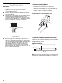
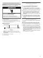
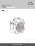
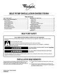
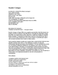
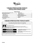
EVAPORATOR COIL INSTALLATION INSTRUCTIONS
Table of Contents
EVAPORATOR COIL SAFETY .......................................................1
INSTALLATION REQUIREMENTS ................................................2
Tools and Parts ............................................................................2
System Requirements..................................................................2
Location Requirements................................................................2
Drain Requirements .....................................................................2
INSTALLATION INSTRUCTIONS ..................................................2
Inspect Shipment .........................................................................2
Prepare Evaporator Coils.............................................................3
Verify Orifice Size .........................................................................3
Assemble Distributor/Orifice ........................................................3
Install Evaporator Coil ..................................................................4
Install Auxiliary Drain Pan.............................................................5
Install Condensate Drains ............................................................5
Connect Refrigerant Lines ...........................................................6
ASSISTANCE OR SERVICE ...........................................................6
Accessories ..................................................................................6
WARRANTY ....................................................................................7
EVAPORATOR COIL SAFETY
Your safety and the safety of others are very important.
We have provided many important safety messages in this manual and on your appliance. Always read and obey all
safety messages.
This is the safety alert symbol.
This symbol alerts you to potential hazards that can kill or hurt you and others.
All safety messages will follow the safety alert symbol and either the word “DANGER” or
“WARNING.” These words mean:
You can be killed or seriously injured if you don't
immediately follow instructions.
You can be killed or seriously injured if you don't
follow instructions.
All safety messages will tell you what the potential hazard is, tell you how to reduce the chance of injury, and tell you
what can happen if the instructions are not followed.
The California Safe Drinking Water and Toxic Enforcement Act requires the Governor of California to publish a list
of substances known to the State of California to cause cancer, birth defects, or other reproductive harm, and
requires businesses to warn of potential exposure to such substances.
WARNING: This product contains a chemical known to the State of California to cause cancer, birth defects, or
other reproductive harm.
This appliance can cause low-level exposure to one of the substances listed: formaldehyde.
065638101
INSTALLATION
REQUIREMENTS
These instructions are intended as a general guide only and do
not supersede any national or local codes in any way.
Compliance with all local, state, or national codes pertaining to
this type of equipment should be determined prior to installation.
Read this entire instruction manual, as well as the instructions
supplied in separate equipment, before starting the installation.
All models are designed for indoor installation only.
Install the conditioned air plenum, ducts and air filters (not
provided) in accordance with NFPA 90B Standard for the
Installation of Warm Air Heating and Air-Conditioning Systems
(latest edition).
Air Filters must be listed as Class 2 furnace air filters.
Tools and Parts
Assemble the required tools and parts before starting installation.
Tools Needed:
■
Torch
■
¹⁄₄ in. Nut driver
■
Tape measure
■
¹³⁄₁₆ in. Open end wrench
■
Flat-blade screwdriver
■
Level
Parts Needed:
Check local codes. Read this entire instruction manual, and
check existing drain configuration before purchasing parts.
■ Field fabricated auxiliary drain pan (in some installations)
Parts Supplied:
Evaporator coil may be provided as a separate coil or
mounted in a duct extension.
Location Requirements
When the evaporator coil is installed in an attic, above a finished
ceiling, or in any location where condensate overflow would
result in property damage, the installer must provide an auxiliary
drain pan in addition to the primary and secondary drains. The
auxiliary drain pan must be connected to a drainage system
separate from the primary condensate drain.
Drain Requirements
■
All vertical mount models come from the factory with right
and left front drain connections.
■
Multiposition models come from the factory with right and left
front drain connections for vertical installations and left front
drain connections when installed in the horizontal position.
■
Minimum ¾ in. copper or PVC drain lines are recommended.
NOTE: Check local codes before connecting drain lines to an
existing drainage system.
■
A field-fabricated auxiliary drain pan, with a drainpipe to the
outside of the building, is required in all installations over a
finished living space or in any area that may be damaged by
overflow from the main drain pan. In some localities, local
codes may require an auxiliary drain pan for any horizontal
installation.
INSTALLATION
INSTRUCTIONS
Inspect Shipment
■
System Requirements
IMPORTANT:
■ The blower and duct system must be properly sized in order
to provide adequate cooling and heating performance. For
proper cooling operation, the airflow through the indoor coil
should be between 350 - 450 CFM per ton of cooling
capacity (or 350 - 450 CFM per 12,000 BTU/H) based on the
rating of the outdoor unit.
■
All air passing over the evaporator coil must be filtered.
■
Evaporator coils are matched to specific outdoor units to
obtain an ARI rating. The orifice installed on each evaporator
coil is chosen for the BTU/H capacity of the coil. The factory
installed orifice size is stamped on the orifice body, and is
identified with a label on the orifice extension stub. The orifice
size must match the size called for on the refrigerant charging
table found on the outdoor unit. A selection of replacement
orifices is available from the distributor.
2
WARNING
Excessive Weight Hazard
Use two or more people to move and install
evaporator coil.
Failure to do so can result in back or other injury.
1. Check the unit rating plate to confirm specifications are as
ordered.
2. Upon receipt of equipment, carefully inspect it for possible
shipping damage. Take special care to examine the unit
inside the carton if the carton is damaged.
If damage is found, it should be noted on the carrier’s freight bill.
Damage claims should be filed with the carrier immediately.
Claims of shortages should be filed with the seller within 5 days.
NOTE: If any damages are discovered and reported to the carrier,
do not install the unit, because your claim might be denied.
Prepare Evaporator Coils
Assemble Distributor/Orifice
IMPORTANT:
■ This evaporator coil was manufactured containing a dry air
precharge of 10 psi. Slowly remove the rubber line seal plugs
to relieve the dry air precharge pressure.
1. Remove brass hex nut from distributor/orifice assembly.
2. Remove line seal plug from the orifice assembly.
3. Unscrew and remove shipping strap from orifice extension
stub. Remove orifice extension stub from panel.
4. Relocate the ring seal to the stub end of the orifice extension
stub as shown.
■
Before installation, carefully wash the coil finned areas with a
mild soap solution to remove shipping and handling
contamination.
Orifice Extension Stub - Before removal of shipping strap
Uncased Evaporator Coil
1
2
1
2
3
1. Orifice extension stub
2. Remove shipping strap
3. Ring seal
3
Orifice Extension Stub - After removal of shipping strap
4
1
2
5
6
1. Orifice extension stub
2. Ring seal
5. Slide the brass hex nut over the orifice extension stub.
6
3
1
8
4
7
1. Suction line header
2. Line seal plug
3. Orifice extension stub
4. Distributor/Orifice
assembly
5. Drain pan
6. Primary drain connections
7. Drain plugs
8. Secondary drain connection
Cased Evaporator Coil
Verify Orifice Size
IMPORTANT: The proper orifice size is dependent on indoor coil/
outdoor unit combination and application. Consult the outdoor
unit information to determine if the indoor unit has the correct
orifice installed.
5
6
2
1. Distributor fitting
2. Mounting flange
3. Piston orifice
4. Ring seal (supplied)
5. Orifice extension stub
6. 0.812 in. Brass hex nut
6. If a change in orifice is required, remove the factory-installed
orifice with an orifice extractor tool.
7. Insert the proper orifice into the fitting, seal end first. Make
sure the orifice is free to move in the fitting.
8. Assemble the brass hex nut and orifice extension stub onto
the distributor/orifice assembly as shown.
NOTE: Overtightening the brass hex nut will crush the gasket
and might result in a system leak or stuck piston
9. Dispose of all packaging and unused parts.
3
Counterflow (Downflow) Models
Install Evaporator Coil
IMPORTANT:
■ The evaporator coil must be installed in the discharge
(supply) air of a gas or oil furnace. Do not install an
evaporator coil in the return air, or excessive condensation
will occur within the furnace.
■
Install the evaporator coil level with the drain connection to
ensure proper drainage.
■
To prevent damage to the plastic drain pan, minimum spacing
is required between the drain pan and a furnace heat
exchanger. A minimum spacing of 2 in. is required for a gas
furnace. A minimum spacing of 4 in. is required for an oil-fired
furnace. See “Evaporator Coil Drain Pan Clearances.”
■
Metal air seals must be placed on the inside of the
evaporator's drain pan to prevent water spray in all
counterflow model installations as shown. Air Seal Kit, Part
No. ACFAIRSEAL-1, is available. The kit contains 4 air seals,
enough to complete 2 counterflow installations.
Air Seal Installation (Counterflow Models Only)
Evaporator Coil Drain Pan Clearances
2
2
Gas 2" Minimum
Oil-fired 4" Minimum
1
1. Air seals before installation
2. Air seals installed
1
1. Furnace heat exchanger
2. Plastic drain pan
■
If the plenum duct work is larger than the drain pan in any
direction, the gaps between the drain pan and the plenum
walls must be closed off to prevent bypass of air around the
sides of the drain pan. Use field fabricated sheet metal angles
wide enough to support the coil where the drain pan is
located and attach them to the inside of the plenum. The
drain pan will rest on the metal angles. If the connection
between the plenum and any duct occurs below the apex of
the coil, seal this seam with sealant.
Installing Air Seals During Evaporator Coil Installation
Install the air seals, hooking the top flange over the internal sides
of the drain opening as shown.
Side View of Drain Pan
1
2
1. Air seal
2. Drain pan
NOTE: Not installing the air seals correctly may result in property
damage due to condensate water being drawn into the furnace.
4
Installing Air Seals After Evaporator Coil Installation
IMPORTANT: Evaporator coil assembly should not be removed
after refrigerant lines have been connected and brazed.
WARNING
Install Auxiliary Drain Pan
(If required)
■
See “Location Requirements” for furnace installation
configurations that require an auxiliary drain pan.
■
Counterflow installations located directly over objects that
can be damaged by condensate, such as in an installation on
a second floor over a finished ceiling, require a auxiliary drain
pan.
■
The auxiliary drain pan should be installed below the supply
plenum. It should be at least 2 in. deep and at least 2 in.
larger in all directions than the supply plenum. A separate
drain line from the auxiliary drain pan to an open drain should
be provided.
■
The open drain should be visible so that any water coming
from the auxiliary drain can be seen as an indicator that the
primary drain is plugged, which should be investigated and
corrected.
Electrical Shock Hazard
Disconnect power before servicing.
Replace all parts and panels before operating.
Failure to do so can result in death or electrical shock.
1. Disconnect power.
2. Remove evaporator coil assembly from the furnace.
3. Install the air seals, hooking the top flange over the internal
sides of the drain opening as shown.
Side View of Drain Pan
1
2
1. Air seal
2. Drain pan
NOTE: Not installing the air seals correctly may result in
property damage due to condensate water being blown into
the supply duct.
Install Condensate Drains
The evaporator coil is provided with ³⁄₄ in. NPT condensate drain
connections.
Make sure unit is level with the drain opening so that the drain
pan will empty completely without water standing in the pan.
1. Connect primary drain line connection to the drain pan (large
hole).
2. Connect secondary drain line connection to the drain pan
(small hole). Route the secondary drain to empty at a location
easily seen, so that any drainage coming from that line would
be noticed. If there is drainage from the secondary drain line,
a problem exists with the primary drain system, which should
be investigated and corrected.
NOTE: Use thread sealant on drain pan fittings. Install drain
lines hand tight. Do not overtighten.
4. Reinstall evaporator coil assembly.
5. Reconnect power.
5
3. Install a 3 in. trap in both the primary and secondary drain
lines as close to the unit as practical. Make sure the top of the
trap is below the connection to the drain pan to allow
complete drainage of the pan.
NOTE: Horizontal runs over 15 ft long must also have an antisiphon air vent (standpipe) installed ahead of the horizontal
run. See “Typical Condensate Drain Connection.” An
extremely long horizontal run may require an oversized drain
line to eliminate air trapping.
Typical Condensate Drain Connection
(secondary drain not shown)
2
1
3
4
1.00" Min.
12.00"
Max.
3.00" Min.
5
1. Evaporator coil
2. Drain connection
3. Drain line
4. Anti-siphon air vent (for horizontal
runs of 15 ft or longer)
5. Drain trap
NOTE: Do not install evaporator coil without a drain trap. The
condensate drain is on the negative pressure side of the blower;
therefore, air being pulled through the condensate line will
prevent positive drainage without a proper trap.
4. Route the drain line to the outside or to an appropriate drain.
Drain lines must be installed so they do not block service
access to the front of the evaporator coil. A 24 in. clearance is
required for filter, coil, or blower removal and service access.
NOTE: Check local codes before connecting the drain line to
an existing drainage system.
5. Insulate the drain lines where sweating could cause water
damage.
Connect Refrigerant Lines
Refrigerant lines must be connected by a licensed, EPA certified
refrigerant technician in accordance with established procedures.
IMPORTANT:
Connecting refrigerant lines must be clean, dehydrated,
refrigerant-grade copper lines. Evaporator coils should be
installed only with specified line sizes for approved system
combinations.
Use care with the refrigerant lines during the installation process.
Sharp bends or possible kinking in the lines will cause a
restriction.
Do not remove the caps from the lines or system connection
points until connections are ready to be completed.
1. Route the suction and liquid lines from the fittings on the
indoor coil to the fittings on the outdoor unit. Run the lines in
as direct a path as possible, avoiding unnecessary turns and
bends.
2. Ensure that the suction line is insulated over the entire
exposed length and that both suction and liquid lines are not
in direct contact with floors, walls, duct work, floor joists, or
other piping.
3. Connect the suction and liquid lines to the evaporator coil.
4. To avoid damaging the rubber grommets in the cabinet while
brazing, slide the rubber grommets over the refrigerant lines
until they are away from the heat source.
5. Braze with an alloy of silver or copper and phosphorus with a
melting point above 1,100°F.
NOTE: Do not use soft solder.
6. Reinstall the rubber grommets after brazing is finished.
7. Make sure outdoor unit has been put in place according to
the Installation Instructions and is connected to the
refrigerant lines.
ASSISTANCE OR SERVICE
Test condensate drain pan and drain line after installation:
1. Pour several quarts of water into drain pan, enough to fill
drain trap and line.
2. Check to make sure the drain pan is draining completely, no
leaks are found in drain line fittings, and water is draining
from the end of the primary drain line.
3. Correct any leaks found.
If you need further assistance, you can write to the below
address with any questions or concerns:
Whirlpool® Home Cooling and Heating
7901 S.W. 6th Court
Plantation, Florida 33324
Please include a daytime phone number in your correspondence.
Accessories
To order accessories, ask for the appropriate part number listed
below or contact your Whirlpool® Home Cooling and Heating
dealer.
ACFAIRSEAL-1
6
Air Seals (4) - for 2 installations
7
Keep this book and your sales slip together for future
reference. You must provide proof of purchase or installation
date for in-warranty service.
Write down the following information about your unit to better
help you obtain assistance or service if you ever need it. You will
need to know the complete model and serial number. You can
find this information on the unit rating plate.
Dealer name____________________________________________________
Address ________________________________________________________
Phone number __________________________________________________
Model number __________________________________________________
Serial number __________________________________________________
Installation date ________________________________________________
065638101
© 2003. All rights reserved.
®/TM Whirlpool and all other trademarks are owned by Whirlpool, U.S.A.,
used under license by Tradewinds Distributing Company, LLC.
4/03
Printed in U.S.A.