1
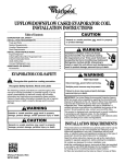
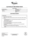
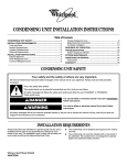
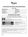
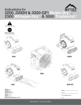
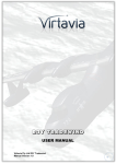
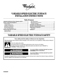
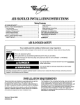
GAS FURNACE USER INSTRUCTIONS
Table of Contents
GAS FURNACE SAFETY................................................................2
GAS FURNACE OPERATION ........................................................3
Lighting the Furnace ....................................................................3
Shutting Down the Furnace .........................................................3
Adjusting the Controls..................................................................3
GAS FURNACE MAINTENANCE...................................................4
Filter Maintenance........................................................................5
TROUBLESHOOTING ....................................................................6
ASSISTANCE OR SERVICE ...........................................................6
Replacement Parts.......................................................................6
WARRANTY ....................................................................................7
WARNING:
FIRE OR EXPLOSION HAZARD
Failure to follow safety warnings exactly could result in serious injury, death or property damage.
— Do not store or use gasoline or other flammable vapors and liquids in the vicinity of this or
any other appliance.
— WHAT TO DO IF YOU SMELL GAS
• Do not try to light any appliance.
• Do not touch any electrical switch; do not use any phone in your building.
• Leave the building immediately.
• Immediately call your gas supplier from a neighbor’s phone. Follow the gas supplier’s instructions.
• If you cannot reach your gas supplier, call the fire department.
— Installation and service must be performed by a qualified installer, service agency or the gas supplier.
To the installer: leave this manual
with the furnace.
To the consumer: read all
instructions in this manual. Keep
all manuals for future reference.
46877J002
Whirlpool® Home Cooling and Heating
7901 S.W. 6th Court
Plantation, Florida 33324
GAS FURNACE SAFETY
Your safety and the safety of others are very important.
We have provided many important safety messages in this manual and on your appliance. Always read and obey all
safety messages.
This is the safety alert symbol.
This symbol alerts you to potential hazards that can kill or hurt you and others.
All safety messages will follow the safety alert symbol and either the word “DANGER” or
“WARNING.” These words mean:
You can be killed or seriously injured if you don't
immediately follow instructions.
You can be killed or seriously injured if you don't
follow instructions.
All safety messages will tell you what the potential hazard is, tell you how to reduce the chance of injury, and tell you
what can happen if the instructions are not followed.
IMPORTANT SAFETY INSTRUCTIONS
■
■
■
■
■
■
The furnace area must be kept clear and free of
combustible materials, gasoline, and other flammable
vapors and liquids.
Insulating materials may be combustible. A furnace
installed in an attic or other insulated space must be
kept free and clear of insulating materials. Examine
the furnace when it is installed and also any time
insulation is added.
For proper and safe operation, the furnace needs air
for combustion and ventilation. Do not block or
obstruct air openings on the furnace, air openings to
the area in which the furnace is installed, and the
spacings around the furnace.
This furnace is equipped with an ignition device which
automatically lights the burners. See the “Gas
Furnace Operation” section for information on lighting
and shutting down the furnace.
Should the gas supply fail to shut off or if overheating
occurs, shut off the gas valve to the furnace before
shutting off the electrical supply.
Do not use the furnace if any part has been under
water. A flood-damaged furnace is extremely
dangerous. Attempts to use the furnace can result in
fire or explosion. A qualified service agency should be
contacted to inspect the furnace and to replace all
gas controls, control system parts, electrical parts that
have been wet, or the furnace if deemed necessary.
■
■
Examine the furnace installation at least once a year
to determine that:
– All flue gas carrying areas external to the furnace,
(i.e. chimney, vent connector) are clear and free of
obstructions.
– The vent connector is in place, slopes upward, and
is physically sound without holes or excessive
corrosion.
– The return air duct connection(s) is physically
sound, is sealed to the furnace casing, and
terminates outside the space containing the
furnace.
– The physical support of the furnace is sound
without sagging, cracks, gaps, etc. around the base
so as to provide a seal between the support and the
base.
– There are no obvious signs of deterioration of the
furnace.
– The pilot and burner flames are in good adjustment.
See the “Gas Furnace Maintenance” section.
It is also recommended that the furnace should be
inspected by a qualified person at least once per
year.
SAVE THESE INSTRUCTIONS
2
Gas Control Valve
GAS FURNACE OPERATION
Thermostat Control
FA N
1
ON
70
50
80
TO
AU
60
OFF
ON
1
C1
3
C2
C3
4
1. Gas control switch
50
60
70
80
2
1. Selector switch
2. Room temperature
3. Fan switch
4. Heating & cooling temperature setting
There are many types and styles of thermostats. Yours may look
different from the one shown, depending on the type of
thermostat and whether cooling was installed with the system.
However, almost all thermostats perform the same basic
functions.
There are two switches located on the thermostat. One switch
controls the heating and cooling (if applicable) functions. The
other switch is for FAN operation, either continuous or automatic.
Also on the thermostat is the temperature range for the desired
heating and cooling temperatures.
Lighting the Furnace
5. Push the gas control switch to ON.
6. Replace the burner compartment access panel (on some
models).
7. Reconnect power.
8. Set the thermostat to the desired setting.
9. If the furnace will not operate, see “Shutting Down the
Furnace” and call a qualified person.
Shutting Down the Furnace
1. To shut down the furnace, set all the household thermostat
control knobs to OFF or to the lowest setting (see Thermostat
Control graphic).
2. Disconnect power.
3. Remove the burner compartment access panel (on some
models).
4. Push the gas control switch to OFF. See “Gas Control Valve.”
5. Replace the burner compartment access panel (on some
models).
Adjusting the Controls
To Turn the System On or Off
■
Move the selector switch to HEAT or COOL to turn the
system on.
■
Move the selector switch to OFF to turn the system off.
Explosion Hazard
Furnace must be installed and serviced by a
qualified person.
Examples of a qualified person include:
To Select the Temperature
Move the thermostat dial or lever to select the temperature you
would like the system to maintain.
licensed heating personnel,
authorized gas company personnel.
Read and follow all instructions provided for
installation, adjustment, service, alteration, or
maintenance.
Failure to follow these instructions can result in death,
explosion, fire, or carbon monoxide poisoning.
To Operate the Fan
You may wish to increase your comfort by setting your system for
continuous circulation of the indoor air. You may do this by
moving the fan switch on the thermostat.
■ Move the fan switch to ON so the fan will operate
continuously.
■
Move the fan switch to AUTO for the fan to operate only when
the unit is either heating or cooling.
1. Set the house thermostat control(s) to the lowest setting.
2. Disconnect power.
3. Remove the burner compartment access panel (on some
models).
4. This appliance is equipped with an automatic ignition device.
Do not try to light the burners by hand.
3
GAS FURNACE
MAINTENANCE
IMPORTANT: It is recommended that the furnace be inspected
and serviced at least once per year by a qualified person.
Servicing should include the items covered in this section.
Your gas furnace is designed to give many years of efficient,
satisfactory service. There are routine maintenance steps you
should take to keep your furnace operating efficiently. This
maintenance will assure longer life, lower operating costs, and
fewer service calls.
In addition to the maintenance procedures listed in this manual,
there are also other service and maintenance procedures that
require the skills of a qualified person.
■ The flue gas passageways should be cleaned.
■
The gas burners should be cleaned.
■
The condensate flow should be checked.
■
The furnace ventilation system should be inspected and
serviced.
■
Lubrication of the bearings in the circulating air blower motor
and the combustion blower motor is not required.
Explosion Hazard
Furnace must be installed and serviced by a
qualified person.
Examples of a qualified person include:
licensed heating personnel,
authorized gas company personnel.
Read and follow all instructions provided for
installation, adjustment, service, alteration, or
maintenance.
Failure to follow these instructions can result in death,
explosion, fire, or carbon monoxide poisoning.
WARNING
Explosion Hazard
Use nonflammable cleaner.
Failure to do so can result in death, explosion,
or fire.
Condensate Collection and Disposal System
Maintenance
If the furnace has a condensate drain, it is incorporated within the
furnace and is self-priming.
Check the condensate flow by shining a flashlight on the
condensate drain. Look for water dripping from the discharge
tube.
If the condensate drain line becomes blocked or plugged, the
furnace will not operate properly. If this occurs, the furnace
should be inspected by a qualified person.
Burner Flame
IMPORTANT: Do not attempt to adjust the burner flame.
While the furnace is in operation, observe the main burner
flames. Compare these observations to “Typical Flame
Appearance” to determine if proper flame adjustment is present.
If your observations indicate improper flame adjustment, call a
qualified person.
Distorted flame or yellow tipping on natural gas flames, or long,
yellow tips on propane flames, may be caused by lint or dirt
accumulation, or obstructions over the main burner orifice. Dirt or
lint can get inside the burner or burner ports, and into the air inlet
between the burner and manifold pipe.
Typical Flame Appearance
3
WARNING:
1
ELECTRICAL SHOCK HAZARD
2
Failure to follow safety warnings exactly
could result in serious injury, death or
property damage.
4
• Before servicing disconnect all electrical
power to furnace.
• When servicing controls label all wires prior
to disconnecting. Reconnect wires
correctly.
• Verify proper operation after servicing.
4
1. Burner
2. Gas manifold
3. Heat exchanger
4. Burner flame (blue only)
■
Vent Maintenance
IMPORTANT:
■ It is recommended that the furnace be inspected and
serviced at least once a year by a qualified person.
■
Should the vent system become blocked at anytime, your
furnace is equipped with a special safety control to prevent
operation of the furnace until the condition has been
corrected. If this occurs, contact a qualified person.
■
Keep the outside area where the vent terminates clear from
any obstructions which might block or impede the venting of
the furnace.
Typical filter sizes are shown; however, any combination of
filters whose area equals or exceeds the minimum area
shown is satisfactory.
Minimum Filter Requirements Chart
Disposable Filters
Cleanable Filters
Airflow
Size
Qty. Min. Area
Size
Qty.
Descriptor Min. Area
(sq. in.)
(in.)
(sq. in.)
(in.)
09
480
20 x 25
1
240
16 x 20
1
10
480
20 x 25
1
240
16 x 20
1
Filter Maintenance
12
576
16 x 20
2
288
16 x 20
1
Your furnace may use either a disposable filter or a cleanable
filter.
IMPORTANT:
■ Do not operate your furnace without a filter. A filter is required
to protect the coil, blower, and internal parts from excessive
dirt and dust.
14
672
20 x 20
2
336
20 x 20
1
16
768
20 x 20
2
384
20 x 20
1
20, 22
960
20 x 25
2
480
20 x 25
1
■
The air filter should be inspected at least every 6 weeks and
cleaned or replaced as required.
NOTE: Dirty filters are the most common cause of inadequate
heating or cooling performance and can sharply increase the
operating costs of your unit.
■
When changing any furnace filter, it is important to measure
the filter being replaced and to replace it with the same size
and type of filter.
■
Install new/clean filters with the arrows on the side pointing in
the direction of airflow.
Filter Location
The filter on your furnace will be located in one of several places
on the unit, depending on which furnace style you own. See the
sections following to determine where your filter is located.
Filter Location - Upflow Models (Side Return)
Replacing/Cleaning Filters
Disposable Filter(s)
If a disposable filter is used, replace with the same filter type
and size.
3
Cleanable Filter(s)
■
■
Cleanable filters may be replaced with disposable filters. See
the Minimum Filter Requirements chart when selecting the
proper size and quantity of disposable filters.
To clean the filter, follow the filter manufacturer’s instructions.
Minimum Filter Requirements
■
The Airflow Descriptor is the 2 digits immediately preceding
the hyphen (-) in the furnace model number. Example 16 is
the Airflow Descriptor for furnace model WFAT075B16-1A.
The model number is located on the rating plate inside the
access panel.
■
Areas and dimensions shown for cleanable filters are based
on filters rated at 600 ft per minute face velocity.
1
2
1. Filter - slides in from front of unit
2. Filter rack
3. Return air duct
If the filter is located in an external filter rack or cabinet on either
side of the furnace cabinet, it may be easily removed, cleaned or
changed, and reinserted in its proper location.
5
Filter Location - Upflow Models (Bottom Return)
1
2
3
4
1. Side
2. Base
3. Filter
4. Front
If the furnace has a bottom return air, remove the lower front
panel by lifting up and pulling out. The filter(s) may be removed
by lifting up and sliding toward the front. Replace in a reverse
procedure.
Filter Location -Counterflow Models and
Horizontal Models
The filters in counterflow furnaces are typically placed by the
installer into the return plenum of the furnace.
TROUBLESHOOTING
First try the solutions suggested here and possibly avoid the
cost of a service call.
Unit fails to operate
ASSISTANCE OR SERVICE
If you need further assistance, you can write to the below
address with any questions or concerns:
Whirlpool® Home Cooling and Heating
7901 Southwest 6th Street
Plantation, FL 33324
Please include a daytime phone number in your correspondence.
Replacement Parts
To order replacement parts contact your Whirlpool® Home
Cooling and Heating dealer.
Gas Control Group
■
Manifold
■
Flame sensor
■
Burner
■
Gas valve/Ignition control
■
Orifice
■
Hot surface igniter
Heat Exchanger Group
■
Primary heat exchanger
■
Secondary heat exchanger (if used)
■
Condensate drain pan (if used)
Blower Group
■
Blower housing assembly
■
Blower motor mount
■
Blower wheel
■
Capacitor
■
Blower motor
■
Inducer blower
Inducer Group
■
Check the following:
Is the main switch that supplies power to the unit in the ON
position?
Has a fuse blown or has the circuit breaker tripped? If
problem continues, call an electrician.
Is the thermostat set properly? See “Adjusting the Controls.”
Unit is operating but not providing complete comfort
■
Check the following:
Is the thermostat set properly? See “Thermostat Control.”
Is the filter clean? Replace or clean filter. See the “Filter
Maintenance" section.
Is the air able to circulate freely throughout your home? Do
not block supply registers or return grilles with furniture
or rugs.
6
■
Pressure switch
Electrical Group
■
Limit control
■
Rollout switch
■
Blower control
■
Auxiliary limit (if used)
■
Transformer
■
Blower door interlock
switch
7
Keep this book and your sales slip together for future
reference. You must provide proof of purchase or installation
date for in-warranty service.
Write down the following information about your furnace to better
help you obtain assistance or service if you ever need it. You will
need to know the complete model and serial number. You can
find this information located on the rating plate on the inside
panel for all models except for model WFCH, which is located on
the outside of the product.
Dealer name ____________________________________________________
Address ________________________________________________________
Phone number __________________________________________________
Model number __________________________________________________
Serial number __________________________________________________
Installation date ________________________________________________
46877J002
© 2003. All rights reserved.
®/TM Whirlpool and all other trademarks are owned by Whirlpool, U.S.A.,
used under license by Tradewinds Distributing Company, LLC.
2/03
Printed in U.S.A.