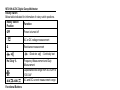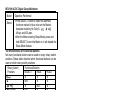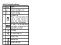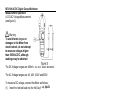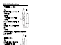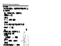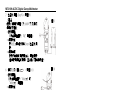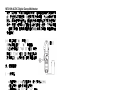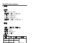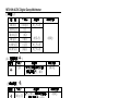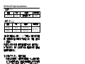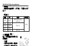
1
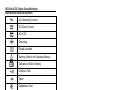
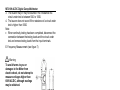
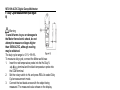
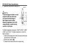
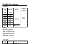
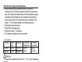
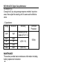
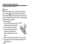
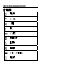
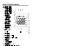
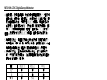
MT-3109 AC/DC Digital Clamp Multimeter User’s Manual st , 1 Edition 2011 ©2011 Copy Right by Prokit’s Industries Co., Ltd. MT-3109 AC/DC Digital Clamp Multimeter Overview This Operating Manual covers information on safety and cautions. Please read the relevant information carefully and observe all the Warnings and Notes strictly. Warning To avoid electric shock or personal injury, read the “Safety Information" and "Rules for Safe Operation" carefully before using the meter. Digital Clamp Multimeter Model (hereafter referred to as "the Meter") is 3 3/4 digits with steady operations, fashionable structure and highly reliable measuring instrument. The Meter uses large scale of integrated circuit with double integrated A/D converter as its core and has full range overload protection The Meter can not only measure AC/DC Voltage, AC/DC Current, Frequency, Duty Cycle, Resistance, Diodes, Continuity but also it has Data Hold, Sleep Mode and Relative Mode features. Unpacking Inspection Open the package case and take out the Meter. Check the following items carefully to see any missing or damaged part: Item Description Qty 1 User’s manual 1 piece 2 Test Lead 1 pair 3 Test Clip 1 pair 4 Carrying Bag 1 piece In the event you find any missing or damage, please contact your dealer immediately. Safety Information This Meter complies with the standards IEC61010: overvoltage category (CAT.II 600V) and double insulation. CAT. II: Local level, appliance, PORTABLE EQUIPMENT etc., with smaller transient over voltages than CAT.III CAT. III: Distribution level, fixed installation, with smaller transient over voltages than CAT. IV 1 MT-3109 AC/DC Digital Clamp Multimeter Use the Meter only as specified in this operating manual, otherwise the protection provided by the Meter may be impaired. In this manual, a Warning identifies conditions and actions that pose hazards to the user, or may damage the Meter or the equipment under test. A Note identifies the information that user should pay attention to International electrical symbols used on the Meter and in this Operating Manual are explained on page Rules for Safe Operation Warning To avoid possible electric shock or personal injury, and to avoid possible damage to the Meter or to the equipment under test, adhere to the following rules: Before using the Meter inspect the case. Do not use the Meter if it is damaged or the case (or part of the case) is removed. Look for cracks or missing plastic. Pay attention to the insulation around the connectors. Inspect the test leads for damaged insulation or exposed metal. Check the test leads for continuity. Replace damaged test leads with identical model number or electrical specifications before using the Meter. Do not apply more than the rated voltage, as marked on the Meter, between the terminals or between any terminal and grounding If the value to be measured is unknown, use the maximum measurement position and reduce the range step by step until a satisfactory reading is obtained When measurement has been completed, disconnect the connection between The test leads and the circuit under test, remove the testing leads away from the input terminals of the Meter and turn the Meter power off. The rotary switch should be placed in the right position and no any changeover of range shall be made during measurement is conducted to prevent damage of the Meter. 2 MT-3109 AC/DC Digital Clamp Multimeter Do not carry out the measurement when the Meter's back case and battery compartment are not closed to avoid electric shock. Do not input higher than 600V between the two Meter's input terminal to avoid electric shock and damages to the Meter. When the Meter working at an effective voltage over 60V in DC or 30V rms in AC, special care should be taken for there is danger of electric shock. Use the proper terminals, function, and range for your measurements. Do not use or store the Meter in an environment of high temperature, humidity, explosive, inflammable and strong magnetic field. The performance of the Meter may deteriorate after dampened. When using the test leads, keep your fingers behind the finger guards. Disconnect circuit power and discharge all high-voltage capacitors before testing resistance, continuity and diode. Replace the battery as soon as the battery indicator appears. With a low battery, the Meter might produce false readings that can lead to electric shock and personal injury. When servicing the Meter, use only the same model number or identical electrical specifications replacement parts. When servicing the Meter, use only the same model number or identical electrical specifications replacement parts. The internal circuit of the Meter shall not be altered at will to avoid damage of the Meter and any accident. Soft cloth and mild detergent should be used to clean the surface of the Meter when servicing. No abrasive and solvent should be used to prevent the surface of the Meter from corrosion, damage and accident. The Meter is suitable for indoor use. Turn the Meter off when it is not in use and take out the battery when not using for a long time. Constantly check the battery as it may leak when it has been using for some time, Replace the battery as soon as leaking appears. A leaking battery will damage the Meter. 3 MT-3109 AC/DC Digital Clamp Multimeter International Electrical Symbols AC (Alternating Current) DC (Direct Current) AC or DC Grounding Double Insulated Warning. Refer to the Operating Manual Deficiency of Built-In Battery Continuity Test Diode Capacitance Test Fuse Conforms to Standards of European Union The Meter Structure (see figure 1) 1. Input Terminals figure.1 2. LCD Display 3. Functional Buttons 4. Rotary Switch 5. Trigger: press the lever to open the transformer jaw 6. Hand Guards: to protect user's hand from touching the dangerous area. 7. Transformer Jaw: designed to pick up the AC and DC current flowing through the conductor. It could transfer current to voltage. The tested conductor must vertically go through the Jaw center. 4 MT-3109 AC/DC Digital Clamp Multimeter Rotary Switch Below table indicated for information of rotary switch positions. Rotary Switch Function Position OFF Power is turned off V AC or DC voltage measurement Ω Resistance measurement : Diode test / Hz / Duty % 40A & 400A : Continuity test Frequency Measurement and Duty Measurement Capacitance test range from 40.OOnF to 1OO.OuF AC and DC current measurement range Functional Buttons Below table for information of functional button operations. Operation Performed Button ● Press HOLD to enter the Hold mode in any mode, HOLD the Meter beeps. ● Press HOLD again to exit the Hold mode, the Meter beeps. and Ω range: At ELA Press select manual ranging measurement mode. The Meter is default to auto ranging measurement mode. When the Meter is at manual ranging measurement mode, press to step down the range. range: At Press enter to the REL mode. It subtracts a stored value from the present measurement value and displays a result. At Hz/Duty% range: Press switch to between Hz measurement mode and Duty % measurement mode. 5 MT-3109 AC/DC Digital Clamp Multimeter Button Select Operation Performed Press SELECT button to select the alternate functions marked in blue color on the Meter's , , faceplate including Hz, Duty%, , and 400 . 40 After the Meter entering Sleep Mode, press and hold SELECT to turn the Meter on, it will disable the Sleep Mode feature. The Effectiveness of Functional Buttons Not every functional buttons can be used on every rotary switch positions. Below table describe which functional buttons can be used on which rotary switch positions Rotary Switch Functional Buttons Positions SELECT RELA HOLD ● ● ● Ω N/A ● ● / ● N/A ● Hz / Duty% N/A ● ● 40 ● ● ● 400 ● ● ● N/A ● ● Display Symbols (see figure 2) 6 MT-3109 AC/DC Digital Clamp Multimeter Symbol Meaning 1 AC Indicator for AC voltage or current 2 DC Indicator for DC voltage The battery is low. Warning: To avoid false readings, which could lead to possible electric shock or personal injury, replace the battery as soon as the battery indicator appears. The Meter is in the auto range mode in which the Meter automatically selects the range with the best resolution. Test of diode No. 3 4 5 The continuity buzzer is on 6 7 % Indicator for Duty. Data hold is active 8 9 Indicator for REL mode 10 Ω: Ohm. The unit3of resistance. kΩ: Kilohm. 1x10 or6 1000 ohms MΩ: Megohm. 1x10 or 1,000,000 ohms The unit of Frequency Ω,KΩ, MΩ 11 Hz 12 A 13 mV, V 14 Amperes (amps). The unit of current. Volts. The unit of -3 voltage. mV: Millivolt. 1xl0 or 0.001 volts Indicates negative reading 15 TRMS Indicator for TRMS mode 16 F,nF,uF, 17 OL Farad. The unit of capacitance. The input value is too large for the selected range 7 MT-3109 AC/DC Digital Clamp Multimeter Measurement Operation A. DC/AC Voltage Measurement (see figure 3) Warning To avoid harms to you or damages to the Meter from electric shock, do not attempt to measure voltages higher than 600V AC/DC, although readings may be obtained The DC Voltage ranges are: 400mV, 4V, 40V, 400V and 600V. The AC Voltage ranges are: 4V, 40V, 400V and 600V. To measure DC voltage, connect the Meter as follows: VΩ (1) Insert the red test lead into the Hz Duty% terminal and the black test lead into the COM terminal. . DC measurement mode and (2) Set the rotary switch to auto ranging is a default. (3) Press SELECT to switch to AC measurement mode or press REL to switch to manual ranging measurement mode. (4) Connect the test leads across with the object being measured. The measured value shows on the display. Note A. When DC/AC voltage measurement has been completed, disconnect the connection between the testing leads and the circuit under test and remove testing leads from the input terminals. B. Measuring Resistance (see figure 4) 8 MT-3109 AC/DC Digital Clamp Multimeter Warning To avoid damages to the Meter or to the devices under test, disconnect circuit power and discharge all the high-voltage capacitors before measuring resistance. The resistance ranges are: 400Ω, 4kΩ, 40kΩ,400kΩ,4 MΩ and 40MΩ. To measure resistance, connect the Meter as follows: terminal 1. Insert the red test lead into the Hz Duty% and the black test lead into the COM terminal. 2. Set the rotary switch to Ω. Resistance measurement is default to auto range mode, press RELA to switch to manual ranging measurement mode. 3. Connect the test leads across with the object being measured. The measured value shows on the display. Note To obtain a more precise reading, you could remove the objects being tested from the circuit when measuring, When resistance measurement has been completed, disconnect the connection between the testing leads and the circuit under test and remove testing leads from the input terminals. C. Testing Diodes (see figure 5) Warning To avoid damages to the Meter or to the devices under test, disconnect circuit power and discharge all the high-voltage capacitors before testing diodes. Use the diode test to check diodes, transistors, and other semiconductor devices. The diode test sends a current through the semiconductor junction, then measure the 9 MT-3109 AC/DC Digital Clamp Multimeter voltage drop across the junction. A good silicon junction drops between 0.5V and 0.8V. To test the diode out of a circuit, connect the Meter as follows: 1. Insert the red test lead into the Hz Duty% -i))-H VQ terminal and the black test lead into the COM terminal. . Diode measurement mode is 2. Set the rotary switch to measurement a default or presses SELECT to select mode. 3. For forward voltage drop readings on any semiconductor component, place the red test lead on the component's anode and place the black test lead on the component's cathode. Note To obtain a more precise reading, you could remove the objects being tested from the circuit when measuring. When diode testing has been completed, disconnect the connection between the testing leads and the circuit under test and remove testing leads from the input terminals. D. Testing for Continuity (see figure 6) Warning To avoid damages to the Meter or to the devices under test, disconnect circuit power and discharge all the high-voltage capacitors before measuring continuity. To test for continuity, connect the Meter as follows: 1. Insert the red test lead into the Hz Duty% terminal and the black test lead into the COM terminal. and press SELECT button 2. Set the rotary switch to measurement mode. The buzzer sounds if to select the resistance of a circuit under test is less than 50Ω 10 MT-3109 AC/DC Digital Clamp Multimeter 3. The buzzer may or may not sounds if the resistance of a circuit under test is between 50Ω to 100Ω 4. The buzzer does not sound if the resistance of a circuit under test is higher than 100Ω Note When continuity testing has been completed, disconnect the connection between the testing leads and the circuit under test and remove testing leads from the input terminals. E. Frequency Measurement (see figure 7) Warning To avoid harms to you or damages to the Meter from electric shock, do not attempt to measure voltages higher than 600V AC/DC, although readings may be obtained. The resistance ranges are: 10Hz, 100Hz, 1kHz, 10kHz, 100kHz, 1MHz and 10MHz. To measure frequency, connect the Meter as follows: 1. Insert the red temperature probe into the Hz Duty% terminal and the black temperature probe into the COM terminal. 2. Set the rotary switch to Hz. 3. Connect the test leads across with the object being test. The measured value shows on the display. Note When frequency measurement has been completed, disconnect the connection between testing leads and the circuit under test, and remove testing leads away from the input terminals. 11 MT-3109 AC/DC Digital Clamp Multimeter F. Duty Cycle Measurement (see figure 8) Warning To avoid harms to you or damages to the Meter from electric shock, do not attempt to measure voltages higher than 600V AC/DC, although reading may be obtained. The duty cycle range is: 0.1% ~99.9%. To measure duty cycle, connect the Meter as follows: 1. Insert the red temperature probe into the Hz Duty% terminal and the black temperature probe into the COM terminal. 2. Set the rotary switch to Hz and press RELA to select Duty Cycle measurement mode. 3. Connect the test leads across with the object being measured. The measured value shows on the display. Note When duty cycle measurement has been completed, disconnect the connection between the testing leads and the circuit under test, and remove the testing leads away from the input terminals of the Meter. G DC/AC Current Measurement (see figure 9) The measurement ranges of current are: and 400.0 40.00 To measure current, do the following: or 1. Set the rotary switch to 40 . DC measurement mode is a 400 default. Presses SELECT to switch between DC and AC measurement mode. 2. Hold the Meter tight, don't release. The Hall components are very sensitive not only to the magnet but also to heat and machines reaction force. Any shock will cause the changing in reading in the short time. 12 2 MT-3109 AC/DC Digital Clamp Multimeter 3. Press the lever to open the transformer jaw. 4. Center the conductor within the transformer jaw, then release the Meter slowly until the transformer jaw is completely closed, Make sure the conductor to be tested is placed at the center of the transformer jaw, otherwise it will cause deviation. The Meter can only measure one conductor at a time, to measure more than one conductor at a time will cause deviation. Note Press RELA to subtracts a stored value from the present measurement value and displays a result. When current measurement has been completed, disconnect the connection between the conductor under test and the jaw, and remove the conductor away from the transformer jaw of the Meter. Sleep Mode To preserve battery life, the Meter automatically turns off if you do not turn the rotary switch or press any button for around 15 minutes. The Meter can be activated by turning the rotary switch or pressing the button based on 'The Effectiveness of Functional Buttons" on page 14. Press SELECT to activate the Meter will disable the Sleep Mode feature. The Meter beeps 5 times in about 1 minute before entering Sleep Mode and it will have a 1 long beep just before entering Sleep Mode. To disable the Sleep Mode function, press and hold SELECT button while turning on the Meter. 13 MT-3109 AC/DC Digital Clamp Multimeter H. Capacitance measurement (see figure 10) figure 10 Warming To avoid damage to the Meter or to the equipment under test, disconnect circuit power and discharge all high-voltage capacitors before measuring capacitance. Use the DC voltage function to confirm that the capacitor is discharged. The Meter's capacitance ranges arc: 40.00nF. 400.0nF, 4.000uF, 40.00uF, and 100.0μF. To measure capacitance, connect the Meter as follows: 1. Insert the red test lead into the HzV Ω terminal and the black test lead into the COM terminal. . 2. Set the rotary switch to 3. Connect the test leads across with the object being measured. The measured value shows on the display. Note For testing the capacitor with polarity, connect the red clip to anode & black clip to cathode instead of using test leads as mentioned above. To minimize the effect of capacitance stored in the test leads, the test lead should be as short as possible. To measure a small value of capacitance, use REL mode to remove the leads capacitance. Remaining voltage, insulated impedance & dielectric absorption from the capacitor may cause the measurement error. It takes a longer time when testing a high capacitor value, the testing time is around 15 seconds in 100uF range. The LCD displays OL indicating the tested capacitor is shorted or it exceeds the maximum range. When capacitance measurement has been completed, disconnect the connection between the testing leads and the circuit under test and remove the testing leads away from the input terminals of the Meter. 14 MT-3109 AC/DC Digital Clamp Multimeter Specifications A. General Specifications: Maximum Voltage between any Terminals and grounding: Refer to different range input protection voltage. Display: 3 3/4 digits LCD display, Maximum display 3999 Polarity: Automatically display. Overloading: Display OL or -OL Battery Deficiency: Display Measurement Speed: Updates 3 times/second. Measurement Deviation: The conductor being measured is not placed in the center of the jaw during AC/DC current measurement, it will cause extra +1 % deviation based on the stated accuracy. Max. Jaw Size: 30mm diameter. Projected Max. Current conductor size: 30mm diameter. Electro-Magnetic: When carrying out measurement near the electro-magnetic, it may cause unstable or wrong reading. Power: 3x1.5V battery ( AAA) (not included) Battery Life: typically 150hours (alkaline battery) Sleep Mode (can be disabled) Dimensions (H x W x 1): 203mm x 68mm x 33mm Weight: Approximate 235g (battery included) B. Environmental Requirements The Meter is suitable for indoor use. Altitude: Operating: 2000m Storage: 1OOOOm Safety/ Compliances: IEC 61010 CAT.II 600V over voltage and double insulation standard. Temperature and humidity: Operating: O℃~30℃(~ 85%R.H); 30℃~40℃ (~ 75%R.H); 40℃~50℃ (~ 45%R.H); Storage: -20℃~+60℃ (~ 85%R.H) 15 MT-3109 AC/DC Digital Clamp Multimeter Accurate Specifications Accuracy: +(a% reading + b digits). Operating temperature: 23℃±5℃ Relative humidity: ( 85%R.H) Temperature coefficient: 0.1x (specified accuracy)1℃ A. DC Voltage Range Resolution Accuracy 400.0mV 0.1mV +(1 %+3) 4.000V 1mV 40.00V 10mV 400.0V 100mV 600V 1V +(1 %+1) Overload protection 600V DC/AC + (1 %+5) Remarks: Input impedance: 10MΩ B_ AC Voltage Range Resolution Accuracy Overload protection 4.000V 1mV + (1.2%+5) 40.00V 10mV 600V DC/AC 400.0V 100mV 600V 1V +( 1 .5 %+5) Remarks: ●Input impedance: 10MΩ// less than 100pF ● Frequency response: 40Hz-400Hz. ● Change to AC: Change to AC by using average response method. Input sine wave, then adjust the reading until it is same as the effective value. 16 MT-3109 AC/DC Digital Clamp Multimeter C. Resistance Range Resolution Accuracy 400.0Ω 4.000kΩ 40.00kΩ 400.0kΩ 4.000MΩ 40.00MΩ 100mΩ 1Ω 10Ω 10Ω 1kΩ 10kΩ +(1.2%+5) D. Diode Test Range Resolution +(1 %+5) Overload protection 600Vp +(1.2%+5) +(1.5%+5) Accuracy 1mV Overload protection 600Vp Display forward voltage drop nearest value Remark: Open circuit voltage approximate 1.48V. E. Continuity Test Range resolution 100mΩ accuracy Around≤50Ω The buzzer beeps Overload protection 600Vp Remark: Open circuit voltage approximate 0.45V. The buzzer may or may not beeps when the resistance of a circuit under test is between 50Ω~1OOΩ The buzzer will not beep when the resistance of a circuit under test is > 1OOQ. 17 MT-3109 AC/DC Digital Clamp Multimeter F. Frequency Range Resolution Overload protection Accuracy 10Hz 0.00Hz 100Hz 0.01Hz 1kHz 0.1Hz +(0.1 %+5) 10kHz 1Hz 100kHz 10Hz 1MHz 100Hz 10MHz 1kHz reference only Remark: Input Sensitivity as follows: When ≤ 100kHz: ≥ 300mV rms; When > 100kHz: ≥ 600mV rms When > 1MHz: ≥ 800mV rms G. Duty Cycle Range Resolution 0.1 % 0.1 % ~99.9% H. DC Current Range Resolution 40.00A 0.01A 400.0A 0.1A Accuracy reference only Accuracy +(2.5%+5) +(2.5%+3) 600Vp Overload protection 600Vp Overload protection 400A DC/AC Warning The operating temperature must be 0℃~40℃ when measuring current. Remark: If the reading is positive, the current direction is from bottom to up. See figure 10, the front case face up while the bottom case face down. Hold the Meter tight, do now release. The hall components are very sensitive not only to the magnet but also to heat and machines reaction force. Any shock will cause the changing in reading in the short time. Follow the below procedure to measure current will be more precise: 18 MT-3109 AC/DC Digital Clamp Multimeter Hold the Meter tight and press the lever to open the transformer jaw. Center the conductor within the transformer jaws, then release the Meter slowly until the transformer jaw is completely closed. Make sure the conductor to be tested is placed at the center of the transformer jaw, otherwise it will cause +1 .0% deviation based on the stated accuracy. Remove the transformer jaw. Press RELA to display zero. Repeat the above 1. procedure. The obtained reading will be more precise. l. AC Current Range Resolu -tion 40.00A 0.01A 400.0A 0.1A Accuracy +(3%+8) +(3%+5) Frequency Response 50Hz ~ 60Hz Overload protection 400A DC/AC Warning The operating temperature must be O℃ ~40℃ when measuring current. Remark: It may have 10 digits or less unstable or wrong digits, it will not affect measurement result. Hold the Meter tight, do now release. The Hall components are very sensitive not only to the magnet but also to heat and machines reaction force. Any shock will cause the changing in reading in the short time. Follow the below procedure to measure current will be more precise: 1. Hold the Meter tight and press the lever to open the transformer jaw. Center the conductor within the transformer jaws, then release the Meter slowly until the transformer jaw is completely closed. Make sure the conductor to be tested is placed at the center of the transformer jaw, otherwise it will cause +1.0% deviation based on the stated accuracy. 2. Remove the transformer jaw. 3. Press RELA to display zero. 4. Repeat the above 1. procedure. 5. The obtained reading will be more precise. 19 MT-3109 AC/DC Digital Clamp Multimeter ●Change to AC: Change to AC by using average response method. Input sine wave, then adjust the reading until it is same as the effective value. J. Capacitance Resolution Range 40nF 10pF 400nF 4uF 40uF 100uF 100pF 1nF 10nF 100nF Accuracy Overload Protection Measure at REL mode ±(5 %+1 0) ±(5%+1 0) 600Vp ±(6%+10) MAINTENANCE This section provides basic maintenance information including battery replacement instruction. Warning Do not attempt to repair or service your Meter unless you are qualified to do so and have the relevant calibration, performance test, and service information To avoid electrical shock or damage to the Meter, do not get water inside the case. A. General Service Periodically wipe the case with a damp cloth and mild detergent. Do not use abrasives or solvents. To clean the terminals with cotton bar with detergent, as dirt or moisture in the terminals can affect readings. Turn the Meter power off when it is not in use. Take out the battery when it is not using for a long time. Do not use or store the Meter in a place of humidity, high temperature, explosive, inflammable and strong magnetic field. 20 MT-3109 AC/DC Digital Clamp Multimeter B. Replacing the Battery (see figure 11) Warning To avoid false readings, which could lead to possible electric shock or personal injury, replace the battery as soon as the " appears. Make sure the transformer jaw battery indicator " and the test leads are disconnected from the circuit being tested before opening the case bottom. To replace the battery: 1. Turn the Meter off and remove all the figure 11 connections from the input terminals 2. Turn the Meter's front case down. 3. Remove the screw from the battery compartment, and separate the battery compartment from the case bottom 4. Take out the old battery and replace with a new 9V battery 5. Rejoin the case bottom and the battery compartment, and reinstall the screw. ** END ** This operating manual is subject to change without notice. 21 MT-3109 AC/DC Digital Clamp Multimeter MT-3109 數位交直流鉗表 中文說明書 一、概述 MT-3109 是一種性能穩定、安全、可靠的 3 3/4 位交直流數字鉗形 表(以下簡稱鉗表)系列。整機電路設計以大規模積體電路雙積 分 A/D 轉換器為核心,全量程的過載保護電路,獨特的外觀設計 使之成為性能優越的專用電工儀表。鉗表可用於測量交直流電 壓、交直流電流、電阻、二極體、電路通斷及頻率等。本使用說 明書包括有關的安全訊息和警告提示等,請仔細閱讀有關內容並 嚴格遵守所有的警告和注意事項。 △警告! 在使用鉗表之前,請仔細閱讀有關“安全操作準則" 二、開箱檢查 打開包裝盒,取出儀表,請仔細檢查下列項目是否缺少或損壞︰ 項次 1 2 3 4 名稱 使用說明書 表棒 帶夾短測試線 布包 數量 1本 1 組 1 組 1 個 如果發現任何一個項目缺少或損壞,請立即與您的供應商進行聯 繫。 22 MT-3109 AC/DC Digital Clamp Multimeter 三、安全操作準則 請注意“警告標識△及警告字句"。警告表示對使用者構成危 險、對儀表或被測設備可能造成損壞的情況或行動。 本儀表嚴格遵循 GB4793 電子測量儀器安全要求以及 IEC61010-1 和 IECI010-2-032 安全標準進行設計和生產,符合雙重絕緣、過電 壓 CAT II 600V、CAT III 300V 和污染等 級 2 的安全標準。如果未能按照有關的操作說明使用鉗表,則可 能會削弱或失去鉗表為您提供的保護能力。 1. 使用前應檢查鉗表和表筆,謹防任何損壞或不止常的現象。如 發現本鉗表表筆、殼體絕緣已明顯損壞以及液晶顯示器等或者 您認為本鉗表己無法正常工作,請勿再使用本鉗表。 2. 後蓋及電池蓋沒有蓋好前嚴禁使用鉗表,否則有電擊危險。 3. 在進行測量時切記手指不要超過表筆擋手部位,不要接觸裸露 的電線、連接器及沒有使用的輸入端或正在測量的電路防止觸 電。 4. 測量前功能開關必須置於正確位置,嚴禁在測量進行中轉換檔 位,以防損壞鉗表。 5. 不要在鉗表終端及接地之間施加 600V 以上電壓,以防電擊和 損壞鉗表。 6. 當儀表在 60V 直流電壓或是 30V 交流有效值電壓下工作時應小 心操作,此時會有電擊的危險存在。 7. 不要測量高於允許輸入值的電壓或電流,在不能確定被測量值 的範圍時須將功能量程開關置於最大量程位置。進行線上電 阻、二極體或電路通斷測量之前,必須先將電路中所有電源切 斷,並將所有電容器放電。測量完畢要斷開表筆與被測電路的 連接,並從鉗表輸入端拿掉表筆以及關斷鉗表電源。 "標誌時,應及時-更換電池,以確 8. 當液晶顯示器顯示“ 保測量精度。鉗表長期不用時,應取出電池。 9. 請勿隨意改變鉗表內部接線,以免損壞儀表和危及安全。 10. 不要在高溫、高濕、易燃、易爆和強電磁場環境下存放或 使用鉗表。 11. 維護保養請使用軟布及中性清潔劑清潔儀表外殼,切勿使 用研磨劑及溶劑,以防外殼被腐蝕而損壞儀表危及安全。 23 MT-3109 AC/DC Digital Clamp Multimeter 四、電氣符號︰ 雙重絕緣 AC(交流) 二極體 接地 DC(直流) 表內電池不足 警告提示 蜂鳴通斷 AC 或 DC(交流或直流) 高壓符號 中國技術監督局 製造計量器具許可證 符合歐洲共同體(European Uion)標準 電容測試 五、外表結構(見圖 1) 1. 輸入端。 2. 液晶數字顯示。 3. 功能按鍵,選擇基本功能。 4. 測量功能轉盤。 5. 鉗頭板機:按壓板機, 使鉗頭張開, 若鬆開板機,則鉗頭局部再度密合。 6. 手部防護:為保護使用者手部碰碰觸到 危險區的一種安全設計。 7. 鉗頭:為測量交流電流的一種裝置,使 電流轉換為電壓,待測電流單一導體必 須穿越鉗頭中心。 24 圖1 MT-3109 AC/DC Digital Clamp Multimeter 六、顯示符號(見圖 2) 1. 交流信號測量指示 2. 直流信號測量指示 3. 電池電量不足指示 4. 自動量程指示 5. 二極體測試指示 6. 連續檢測指示 7. 占空比測量指示 8. 數據保持指示 9. 相對值測量指示 10. 電阻測量單位(Ω 歐姆、kQ 千歐、 MQ 兆歐) 11. 頻率測量單位 12. 電流測量單位(A 安培) 13. 電壓測量單位(mV 毫伏、V 伏特) 14. 負極性指示 15. 真有效值測量指示 16. 電容測量單位(F, nF, uF) 17. 對所選量程輸入信號太高,表示溢出 圖2 七、按鍵功能及自動關機 1. HOLD:為讀數保持鍵,以觸發模式工作,功能為保持顯示讀數。 按一次此鍵顯示值被鎖定,一直保持不變。再按一次此鍵,鎖 定狀態被解除,返回通常測量狀態。 2. REL△︰為多功能組合鍵,以觸發模式工作。在 V 及Ω測量檔 位時,作為 RANGE 鍵使用,鉗表開機預設為自動量程。按一下 此鍵即切換為手動量程。在手動量程狀態下,按一下此鍵即往 上跳一檔,如果在最高檔位則跳至最低檔位。按住此鍵超過 2 秒鐘,即切換為白動量程,在 A-測量檔位時,作為 REL△鍵使 用,按此鍵後使鉗表將當前顯示值作為參考值,並將顯示 “O",在此之後的測量結果中將自動減去參考值,直到再按此 鍵退出相對值測量功能,在 Hz 測量檔位時,作為 Hz/Duty%鍵使 用,按此鍵後,可以使鉗表再 H z 測量和 Duty%測量模式之間的 切換。 3. SELECT:為功能選擇鍵,以觸發方式工作,用此鍵可作為 V、A、 測量檔時測量方式的切換。 及 注意︰在自動關機後,若按著 SELECT 鍵開機,自動關機功能將 被取消。 25 MT-3109 AC/DC Digital Clamp Multimeter 4. 自動關機︰在測量過程中,功能按鍵和轉盤開關在 1 5 分鐘內均 無動作時,鉗表會“自動關機"(休眠狀態),以節約電能; 要 取消自動關機功能,只要按著 SELECT 鍵開機,則自動關機功 能被取消。自動關機狀態下,按功能鍵(有效的按鍵操作,詳 見 6.)或是轉動轉盤開關,鉗表會“自動開機"(工作狀態)。 注意︰在休眠狀態下按 SELECT 鍵喚醒,自動關機功能被取消。 5. 蜂鳴器︰在任一測量檔位按動任意功能按鍵,如果該鍵有效, 蜂鳴器會發“嗶"的一聲,無效則不發聲; 自動關機前約 1 分鐘 蜂嗚器會連續發出 5 聲警示; 關機前蜂嗚器會以 1 長聲警示。 6. 按鍵的有效性︰並非所有的按鍵操作在任一檔位上都是有效 的,只有有效的按鍵操作,才能選擇相應的操作功能或喚醒休 眠狀態下的儀表,見下表︰ 檔位 Hz SELECT ● N/A ● N/A ● ● N/A REL△ ● ● N/A ● ● ● ● HOLD ● ● ● ● ● ● ● 八、測量操作說明 警告:鉗表不得用於電壓大於 600V 交流/直流導電的物體上 )(見圖 3) 1.直流電壓測量( 圖3 ﹡設定轉盤 將功能轉盤置於“ "測量檔。 ﹡選擇按鍵功能 直流電壓測量為最初設定值,最初 設 定為自動量程,按 REL△鍵設定為手 動量程。 ﹡連接負載 在完成所有的測量操作後,要斷開表 棒與被測電路的連接,並從輸入端拿 掉表棒。 26 MT-3109 AC/DC Digital Clamp Multimeter 2.交流電壓測量(V )(見圖 4) △警告 圖4 鉗表不得用於電壓大於 600V 交流/直 流導電的物體上 ﹡設置轉盤 "測量檔。 將功能轉盤置於“ ﹡選擇功能 按 SELECT 鍵選擇為交流電壓測量,最 初設置 為自動量程,按 REL△鍵可設置為手動 量程。 ﹡連接負載 在完成所有的測量操作後,要斷開表棒與被測電路的連接, 並從輸入端拿掉表棒。 圖5 3.電阻測量(Ω) (見圖 5) △警告 在連接負載以前務必將電路電源切斷, 並將所有電容器放盡殘餘電荷 ﹡設定轉盤 將功能轉盤置於“Ω"測量檔。 ﹡選擇功能 最初設定為自動量程,按 REL△鍵可設 定為手動量程。 ﹡連接負載 若將元件從電路中分離出來測量可得到較好的結果。在完成所有 的測量操作後,要斷開表棒與被測電路的連接, 並從輸入端拿掉表棒。 4.二極體測量( ) (見圖 6) △警告 圖6 在連接負載以前務必將電路電源切斷,並 將所有電容器放盡殘餘電荷。 ﹡設置轉盤 "測量檔。 将功能轉盤置於“ ﹡選擇功能 測量為最初設定值。 ﹡連接負載 若將元件從電路中分離出來測量可得到 27 MT-3109 AC/DC Digital Clamp Multimeter 較好的結果。 在完成所有的測量操作後,要斷開表棒與被測電路的連接,並從 輸入端拿掉表棒。 △警告:在連接負載以前務必將電路電源切斷 位置 ﹡設置轉盤到 ﹡選擇功能 按 SLLECT 鍵選擇二極體測 ﹡連接負載 若將元件從電路中分離出來測量可得到較好的結果。 )(見圖 7) 5.導通檢測( 圖7 △警告 在連接負載以前務必將電路電源切斷,並 將所有電容器放盡殘餘電荷 ﹡設定轉盤 "測量檔。 將功能轉盤置於“ ﹡選擇功能 按 SELECT 鍵選擇. 導通檢測 ﹡連接負載 在導通測試中測量電阻小於 50Ω時蜂嗚 器會響,在 50Ω到 100Ω時蜂鳴器可能響 或不響,大於 100Ω 時蜂鳴器不響。 在完成所有的測量操作後,要斷開表棒與被測電路的連接,並從 輸入端拿掉表棒。 6.頻率測量(Hz)(見圖 8) △警告 鉗表不得用於電壓大於 600V 交流直流 導電的物體上 ﹡設定轉盤 將功能轉盤置丁“Hz"測量檔。 ﹡選擇功能 Hz 頻率測量為最初設定值。 ﹡連接負載 在完成所有的測量操作後,要斷開表棒 與被測電路的連接,並從輸入端拿掉表 棒。 28 圖8 MT-3109 AC/DC Digital Clamp Multimeter 7.占空比測量( Duty%)(見圖 9) △警告 鉗表不得用於電壓大於 600V 交流/直流 導電的物體上 ﹡設定轉盤 將功能轉盤置於`Hz"測量檔。 ﹡選擇功能 按 REI△鍵可設定為 Duty%占空比測 最。 ﹡連接負載 在完成所有的測最操作後,要斷開表 筆與被測電路的連接,並從輸入端拿掉表筆。 8.直流电流测量( ) (見圖 10) 圖9 圖 10 ﹡設定轉盤 將功能轉盤置於“40A "或 “400A "測量檔。 ﹡選擇功能 直流電流測量為最初設定值。 ﹡連接負載 按住板機不要突然鬆開,鉗頭內置的霍爾 元件是一種敏感器件,除了對磁敏感外, 對熱、機械應力均有不同程度的敏感,撞 擊會短時間引起讀數變化。按住板機打開鉗頭,將鉗頭夾取待測 導體,然後緩慢地放開板機,直到鉗頭完全閉合,請確定待測導 體是否被夾取在鉗頭的中央,未置於鉗頭中心位置會產生附加誤 差,鉗表一次只能測量一個電流導體,若同時測量兩個或以上的 電流導體,測量讀數會是錯誤的。 ) (見圖 11) 9.交流電流測量(A ﹡設定轉盤 "或 將 功 能 轉 盤 置 於 “ 40A “400A "測量檔。 ﹡選擇功能 按 SELECT 鍵選擇為交流電流測量。 ﹡連接負載 按住板機不要突然鬆開,鉗頭內置的霍爾 元件是一種敏感器件,除了對磁敏感外, 29 圖 11 MT-3109 AC/DC Digital Clamp Multimeter 對熱、機械應力均有不同程度的敏感,撞擊會短時間引起讀數變 化。按住板機打開鉗頭,將鉗頭夾取待測導體,然後緩慢地放開 板機,直到鉗頭完全閉合,請確定待測導體是否被夾取在鉗頭的 中央,未置於鉗頭中心位置會產生附加誤差,鉗表一次只能測量 一個電流導體,若同時測量兩個或以上的電流導體,測量讀數會 是錯誤的。 1 0.電容測試( )(見圖 1 2) "測量檔 將功能轉盤置於" 將紅色表棒插入“HzV Ω"插孔,黑表 棒插入“COM"插孔,並將表筆並聯到 被測電容上.從顯示器上讀取測量結果 圖 12 九、技術指標 1.一般規格 液晶顯示︰3 3/4 位液晶顯示,最大顯示至 3999. 極性顯示︰自動正負極性顯示 過載顯示︰以“OL"或“-OL"顯示 "符號顯示電池電壓低於工作電 低電壓顯示︰ “ 壓,做為更換電池的參考 取樣率︰3 次/秒 傳感器種類︰DC/AC 測量的霍爾效應傳感器 測試位置誤差︰測量電流時因為未將待測源置於鉗頭中心位 置會產生±1.0%讀數附加誤差 鉗頭開啟最大尺寸︰直徑 30mm 預測電流導線最大尺寸︰直徑 30 mm 電磁場影響︰使用於靠近電磁場產生的裝置,可能顯示不穩 定或顯示不正確的讀數 電源需求︰三個 AAAl.5V 電池(不含) 電池壽命︰典型為 150 小時(鹼性電池) 自動關機功能(可以在使用時取消該功能) 尺寸︰68mm(寬)×203(長)×33 mm(高) 重量︰約 220(不包括電池) 30 MT-3109 AC/DC Digital Clamp Multimeter 2.環境限制 室內使用 安規︰ICE 1010-1 CAT. II600V 操作溫濕度︰0℃到 30℃(不大於 80%R.H) 30℃到 40℃(不大於 75%R.II.) 40℃到 50℃(不大於 45%R.H.) 儲存溫濕度︰-20℃到+60℃(不大於 80%R.H.) 3.電氣規格 準確度︰±(%讀數+位數),校準期為一年 環境溫度︰23℃±5℃ 環境濕度︰小大於 80%R.H. 溫度系數︰0.1×精度/l℃ ) (1)直流電壓( 量程 分辨力 準確度 過載保護 400. 0 mV 0. 1 mV ±(1%+3) 4.000 V 1 mV 600V DC/AC ±(1%+1) 40.00 V 10 mV 400.0 V 100 mV 600 V 1V ±(1%+5) 輸入阻抗︰10 M Ω (2)交流電壓(V) 量程 分辨力 4.000 V 1 mV 40.00 V 10 mV 400.0 V 100 mV 600 V 1V 輸入阻抗︰10M Ω//100pF 頻率附應︰40Hz~400Hz 準確度 ±(2%+5) 過載保護 600V DC/AC ±(1.5%+5) AC 轉換類型︰ AC 轉換是用平均值附應模式,以正弦波輸入、校正讀數至與有效 值一致。 31 MT-3109 AC/DC Digital Clamp Multimeter (3)電阻(Ω) 量 程 400.0 Ω 4.000 KΩ 40.00 KΩ 400 KΩ 4.000 MΩ 40.00 MΩ 分辨率 100 mΩ 1Ω 10Ω 100Ω 1KΩ 10KΩ (4)二極體測試( ) 分辨力 量程 1mV 準確度 ±(1.2%+5) 過載保護 ±(1%+5) 600Vp ±(1.2%+5) ±(1.5%+5) 準確度 顯示正向壓降近似值 (開路電壓約 1. 48V) 過載保護 600Vp ) (5)導通測試( 量程 分辨力 準確度 過載保護 約≦500Ω 時蜂鳴器會響 600Vp 100 m Ω (開路電壓約 0. 45V) 注意︰在導通測試中量測電阻在 50Ω ~100Ω 時蜂鳴器可能響或 不響,>100Ω 時蜂鳴器不響。 (6)頻率(Hz) 量程 分辨力 準確度 10 Hz 0. 001Hz 100 Hz 0.01Hz 1k Hz 0. 1Hz ±(0.1%+5) 10k Hz 1Hz 100k Hz 10Hz 1M Hz 100Hz 10M Hz 1kHz (讀數僅供參考) 靈敏度:≦l00kHz 時:≧300mV rms; >l00kHz 時:≧600mV rms >1MHz 時:≧800mV rms 32 過載保護 600Vp MT-3109 AC/DC Digital Clamp Multimeter (7)占空比(Duty%) 量程 0. 1%-99. 9% (8)直流电流( 量程 40. 00A 400.0A 分辨力 0. 1% 準確度 (讀數僅供參考) 過載保護 600Vp ) 分辨力 0.01A 0.1A 準確度 ±(2.5%+5) ±(2.5%+3) 過載保護 400A DC/AC 注意: 電流測量功能必須在 0℃~40℃之間操作。在直流電流測量 時,如果讀數為正值,則電流的方向為由下到下(見圖 10:面板為 上,底蓋為下)。 按住板機不要突然鬆開,鉗頭內置的霍爾元件是一種敏感器件, 除了對磁敏感外,對熱、機械應力均有不同程度的敏感,撞擊會 短時問引起讀數變化。 測量更加準確: 如下的操作方法將使 按住板機打開鉗頭,將鉗頭夾取待測導體,然後緩慢地放開板 機,直到鉗頭完全閉合,請確定待測導體是否被夾取在鉗頭 的中央,未置於鉗頭中心位置會產生±1. 0%讀數附加誤差; 將電流導體上的鉗頭移開; 按 REL△鍵使顯示歸零; 重複如上步驟 ; 讀數。 如此測量的結果將可得到更準確的 (9)交流電流(A ) 量程 分辨力 40. 00A 0.01A 400. 0A 0. 1A 準確度 ±(2.5%+8) ±(2.5%+5) 頻率 50Hz~ 60Hz 過載保護 400 DC/AC 注意: 電流測量功能必須在 O℃- 40℃之問操作。 在交流電流檔位時,可能會顯示 1 0 個字以下不穩定的或不正確的 感應讀數,不會影響測量結果。 按住板機不要突然鬆開,鉗頭內置的霍爾元件是一種敏感器件, 除了對磁敏感外,對熱、機械應力均有不同程度的敏感,撞擊會 短時間引起讀數變化。 33 MT-3109 AC/DC Digital Clamp Multimeter AC 轉換類型︰ AC 轉換是用平均值附應模式,以正弦波輸入、校正讀數至與有效 值一致。 (10)電容值( 量程 ) 分辨力 40nF 10pF 400nF 4μF 40μ F 100μF 100pF 1nF 10nF 100nF 準確度 Measure at REL mode ±(5%+1 0) ±(5%+1 0) 過載保護 600Vp ±(60%+10) 十、保養和維護(見圖 13) 警告:在打開底蓋前為避免電擊,請 圖 13 移開測試棒。 1.一般維護 a.本鉗表的維修與服務必須由有資 格的專業維修人員或指定的維修 部門完成。 b.定期性使用乾布去清潔外殼,但不 得使用含有研磨妝或溶劑成份的 清潔劑。 2.電池安裝或更換 本產品的電力為三顆 1.5V AAA 電池,按下列順序安裝或更換 電池。 a.本產品關機,請移開位於輸入端之測試棒。 b.將本產品面板朝下,並旋開電池盒螺絲,拔下電池蓋。 c.從電池倉上取下舊電池,按照極性指示安裝新電池。 d.請使用同一型號的從 A 電池,不要安裝不適當的電池,新舊以 及不同型號的電池不能混裝使用。 e.安裝新的電池後,裝上包池蓋,並鎖上螺絲即可。 34 MT-3109 AC/DC Digital Clamp Multimeter ©2011 Prokit’s Industries Co., LTD. All rights reserved 2011001(T) 35