1
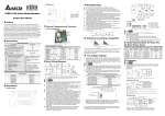
MT-2017 Protective Function Analog Multimeter User’s Manual st , 1 Edition 2013 ©2013 Copyright by Prokit’s Industries Co., Ltd. INTRODUCTION This Multi-meter is an accurate, safe, battery operated, rear tilt-stand, easy to operate handheld instrument with robust protective holster alongside and the adjustable back tilt device with hook-up design. It can offer accurate, reliable measurement of DC/AC Voltage, +/-DCV, DC Current, Resistance and Diode, LED, Transistor, Decibels, Continuity test and Capacitance with very high sensitive quality movement, double-sided glass-epoxy PCB & good-designed circuit, as well as mirrored Aluminum dial plate etc. It has the perfect full overload & mis-used protection via two Fuses, Oxide Varactor & Diodes. It is an ideal instrument for indoor use in the laboratory, school, workshop, hobby and home applications. SPECIFICATION Safety Category: IEC61010-1, CAT II 1000V, CAT III 500V and Pollution Degree 2. Common Environment: 23C5C, less than 75% RH. Temperature Ranges: 0C to 40C, 32 F to 104 F for operating condition. -10 C to 50C, 14 F to 122F for storage condition. Humidity Scope: Operating condition less than 90% RH. Storage condition: less than 80% RH. Size: 160(W) x 105(D) x 40(H) MM Weight: 390g approx. (including batteries 3pcs) Accessories: One set of Test Leads; Two Spare Fuses: 0.5A/250V & 10A/250V, Additional Option Accessory: MT-2007-C special for capacitance measurements 1 set 1 Test Functions DC V Range Accuracy 0-0.1-2.5-10-50250 V-1000V 3% FSD. 4% FSD. For 1000V Input Impendence: 20KΩ/V Overload Protection: Max. 1000V AC/DC BUT 0.1V/2.5V/10V 250V Max. Null DCV ±-5V, ±25V 5% FSD. Input Impedance: 40KΩ/V Overload 1000V Max. AC V 0-10-50-250V -1000V 4% FSD. 5% FSD. For 1000V DC mA 0-0.05-2.5-25-25 0 mA, 10A 3% FSD. 4% FSD. For 10A Ω X 1: 0.2 ~ 2KΩ Midscale at 20Ω X 10: 2 ~ 20KΩ Midscale at 200Ω X 100: 20~ 200KΩ Midscale at 2000Ω X1K: 200~ 2MΩ Midscale at 0KΩ X10K: 2K ~20MΩ Midscale at 200KΩ 4% of ARC of Scale Length Input Impendence: 9KΩ/V Overload Protection: Max. 1000V AC/DC But 10V/50V only 250V Max. Band width: 40 ~10K Hz Drop Voltage: 250 mV Overload protected by Fuses 0.5A/250V & 10A / 250V at 10A range, and Oxide Varactor.<250V AC/ DC(5s). Max. test time 1min. for 10A. Overload protected by the Oxide Varactor & Fuse <250V AC/DC (5s). 2 Remarks 0.025-0.25-25uF (C2) 3% FSD. 2000uF(C1) Approx. Value BATT Check 0 ~ 1.5V: GOOD - ? – BAD 0 ~ 9V: GOOD - ? – BAD 5% of ARC of Scale Length Transistor Check hFE: 0-1000 via special hFE socket via special hFE socket Approx. Value Approx. Value At Ω X 10 Range -22 dB ~ + 62 dB (0dB=1mW at 600Ω) Beeper sounding under 200 Ohm Approx. Value At ACV ranges Capacitan ce (uF) LED, Diode Check Decibel Continuity Check POWER Source Use the optional Accessory Kit (MT-2007-C) Use the R x 1K range Load Current: 270mA for 1.5V 25mA for 9V Overload protected by Fuse & Oxide Varactor .<250V AC/DC(5s). At Ω X 10 Range Overload protected by Fuse & Oxide Varactor .<250V AC/DC(5s). Internal Battery: R6P, AA, 1.5V 2pcs, 6F22, NEDA1604, 9V 1pc CALIBRATION Ohms Zero Adjustor located at the right side of the panel, adjusting the meter pointer to the Zero mark on the right side of Ohm scale of the meter dial when the test leads are touched together. Mechanical Adjustor Screw: located right below the center of the meter dial to set pointer to Zero mark at the left side of the 3 scale. (-) Jack: Plug-in connector at the lower left on the panel for Black, negative test lead. (+) Jack: Plug-in connector at the lower right on the panel for Red, positive test lead. OPERATING INSTRUCTIONS CAUTION When making voltage or current measurements, develop the habit of turning off all power to the circuit under test. Connect the test leads at the desired points in the circuit, and then turn on the power while taking readings. Turn off the power before disconnecting the test leads from the circuit. INTERNAL BATTERY CHECK To check the battery condition, insert the black test lead into the (-) jack. Set the range switch to the R X1 range position and short the ends of the two sides of the test leads. If the pointer can not be brought to the zero mark, replace the 1.5V cells or 9V cell. (See battery replacement.) BEFORE OPERATING 1. Set the range switch to the proper position before making any measurement. 2. Never apply more voltage or current than the rated value in every position. 3. When the voltage or current to be measured it not known, always start with the highest range. 4. If meter indication is in the lower half of the scale and falls within the range of a lower scale, reset selector switch to the lower range for greatest accuracy. 5. If the meter won’t work at all, check the fuse located on the 4 PCB. If it’s blown, replace it. (See fuse replacement.) 6. Avoid placing the meter where extreme shock or continuous vibration is encountered and do not store in excessively hot or damp places. Although very rugged, the meter is a sensitive measuring device and should be handled carefully & properly. 7. Do not check resistance, transistor, diode, LED, or capacitance when live voltage or current input across the circuit. 8. When the meter is not in use, keep the selector switch to the “OFF” range position, this provides direct short across meter movement for minimum needle bounce when transporting meter. 9. If you should accidentally apply excessive voltage or current on a certain range, disconnect the leads from the circuit as quickly as possible, check instrument operation on that range by applying peoper input. If the meter does not operate peoperly, check fuse. If it is blown replace it. (See fuse replacement.) 5 OPERATION PROCEDURES DC Voltage Measurement WARNING: WITH EXTREME CARE WHEN MAKING MEASUREMENTS FOR HUGE VOLTAGE. DO NOT TOUCH TERMINAL OR PROBE ENDS. 1. Set the selector switch to the appropriate DCV range to be used. 2. Connect the BLACK test lead to the “-COM” jack and the RED test lead to the “+” jack. 3. If you know the polarity of the circuit to be tested, connect the black probe to the negative side. 4. If you don’t know the polarity, connect the probes to opposite sides of the circuit and watch the pointer. If it goes to the left, reverse the probes. The RED probe will be connected to the positive. 5. Check the needle position and the get the reading on V.A scale. Null DCV (Central Zero) Measurement At these two ranges, it can automatically judge the polarity of circuit as the pointer can move to the center line and become a Null meter. 1. Set the selector switch to the DCV ±5V or 25V range. 2. Connect the BLACK test lead to the “-COM” jack and the RED test lead to the Red “+” jack. 3. Set the Zero Ω adjustor to place the pointer exactly to the Central Zero position if need. 4. Connect the test leads across the circuit or load under measurement. 5. Take the readings on the Red dial Null DCV scale. NOTE: If the needle failed to be set at Central Zero position, the power of 9V battery may be weak and should be replaced by new one for normal working. 6 AC Voltage Measurement WARNING: WITH EXTREME CARE WHEN MAKING MEASUREMENTS FOR HUGE VOLTAGE. DO NOT TOUCH TERMINAL OR PROBE ENDS. 1. Set the selector switch to the appropriate ACV range to be used and connect the test leads across the circuit or load under measurement. (Polarity of the test probes is unimportant on ACV test.) 2. Connect the BLACK test lead to the “-COM” jack and the RED test lead to the“+” jack. 3. Check the needle position and the get the reading on V.A scale. DC Current Measurement WARNING: DO NOT APPLY VOLTAGE TO MEASURING TERMINAL WHILE RANGE SWITCH IS IN CURRENT POSITION. DO NOT ATTEMPT TO MEASURE AC CURRENT. 1. Set the selector switch to the appropriate DC mA range to be used and connect the test leads in series with the circuit or the load under measurement. If the pointer deflects to the left, reverse the probes. 2. Connect the BLACK test lead to the “-COM” jack and the RED test lead to the Red “+” jack for Current at/less than 0.25A. For large current max. 10A, move the red test lead to the Red “10A” jack. 3. Check the needle position and the get the reading on V.A scale. Note: Excessive current input across mA range will blow the fuse that must be replaced by a same fuse rating 0.5A/250V or 10A/250V. The max. testing time shall be not more than 1min. for big current load. 7 The Maximum terminal voltage drop is 250mV except for the 10A range. Note: If connected incorrectly with the voltage at these ranges, quickly remove the test leads from the circuit as to avoid damage to this tester. (This tester can afford the voltage <250V DC/AC rms. for the period of 5 seconds max.) Resistance Measurement WARNING: DO NOT APPLY VOLTAGE TO MEASURING TERMINAL WHILE RANGE SWITCH IS IN OHM POSITION. 1. Set the selector switch to the appropriate Ω range to be used. 2. Connect the BLACK test lead to the “-COM” jack and the RED test lead to the Red “+” jack. 3. Short the leads by touching the probes together. Pointer should read zero at the right hand end of the upper most scale, if it doesn’t, use the Ohm adjust knob on the right hand of the panel to line up the pointer with zero. (If pointer can’t be brought to zero, replace battery.) 4. Connect the test leads across the resistance to be measured. 5. Take reading on the top “Ω” scale and multiply it by the multiplication factor indicated by the selector switch. 6. If there is little or no pointer movement from the left side of the scale, reset the selector switch to higher range. The effective reading scope on an Ohm meter scale is within the area of between 25 degree of Arc left side to the Midscale and 25 degree right side to the Midscale. Note: If connected incorrectly with the voltage, quickly remove the test leads from the circuit as to avoid damage to this tester. (This tester can afford the voltage <250V DC/AC rms. for the period of 5 seconds max.) 8 Diode Measurement 1. Set the selector switch to the appropriate Ω range to be used. NOTE: To test the diode while current below 0.060 mA at X 10K range; current below 0.15 mA at X 1K range; current below 1.5 mA at X 100 range; current below 15 mA at X 10 range; current below 150 mA at X 1 range. 2. For IF (forward current) test, put the BLACK test lead to the “-COM” jack and the RED test lead to the Red “+” jack. And then connect the Black probe to the Positive terminal of the Diode, the Red probe to the Negative terminal of the Diode. For IR (reverse current) test, reverse the connection. 3. Read the value IF or IR of the diode on the LI scale. 4. Read the linear (forward voltage) VF of the diode on the LV scale. Continuity Test WARNING: DO NOT APPLY VOLTAGE TO MEASURING TERMINAL WHILE RANGE SWITCH IS IN OHM POSITION. Set the selector switch to the BUZZ range. Connect the test leads to two points of circuit. If the resistance is lower than 200 Ohm approx., the Beeper sounds. Note: Battery voltage is sufficient for Buzzer operation as long as the Zero Ohm pointer can be adjusted to the Zero scale place. Note: If connected incorrectly with the voltage, quickly remove the test leads from the circuit as to avoid damage to this tester.. (This tester can afford the voltage <250V DC/AC rms. for the period of 5 seconds max.) 9 Transistor hFE and LED Test 1. Set the selector switch to the R X 10 range. FOR Measuring Transistor hFE 2. Take note the type of transistor “PNP” or “NPN” and then insert the transistor terminals of the Emitter, Base and Collector separately into the proper holes of the socket on the front panel. 3. Read the approximate hFE Value directly at the hFE scale. Note: Current 10μA. VCE 2.8V. 4. When the Base terminal cut, the value of Leak is Iceo for Transistor. FOR Measuring LED: Insert the transistor terminals directly into the “+” and “-” holes of the socket on the front panel. And then check if the LED under testing is lighting. Battery Check 1. This meter can come with two separate battery check ranges to test either DC 1.5V or 9V batteries. 2. Set the selector switch to the appropriate BATT range to be used. 3. Connect the BLACK test lead to the “-COM” jack and the RED test lead to the Red “+” jack. 4. Connect the Red test lead to the positive end of battery and the Black one to the negative end of the battery to be measured. 5. Take reading on the “BATT” scale and check it good or bad as per which portion indicated. (Note: the mark section of “?” shows that the battery may be starting to decay.) Note: If connected incorrectly with the voltage, quickly remove the test leads from the circuit and can avoid the damage to this tester. (This tester can afford the voltage <250V DC/AC rms. for the period of 5 seconds max.) 10 Decibels Measurement 1. Set the selector switch to AC 10V range. 2. Connect the BLACK test lead to the “-COM” jack and the RED test lead to the Red “+” jack. 3. Connect the test leads to the measuring circuit specially in series with a 0.047μF/400V Metalized Polyester Capacitor. And then read the bottom Red dB scale. 4. For more dB scope, change the selector switch to the others of ACV ranges and make the same actions. Add the appropriate number of dB scale reading as noted on the chart below. NOTE: For absolute dB measurements, circuit impedance must be 600 Ohm. 0 dB = 1mw dissipated in a 600 Ohm impedance (equivalent to 0.755V across 600 Ohm) ACV RANGE 50 250 1000 ADD dB Number 14 28 40 Capacitance Measurement with the optional accessory kit of Item no. MT- 2007-C WARNING: DO NOT APPLY VOLTAGE TO MEASURING TERMINAL WHILE MAKING ANY CAPACITANCE MEASUREMENTS. BEFORE TESTING ANY CAPACITORS, DISCHARGE THE CAPACITOR COMPLETELY. BEFORE MEASUREMENTS, PLEASE READ THE INSTRUCTIONS OF MT- 2007-C CAREFULLY. 11 1. For Measuring the Capacitor over 25uF: 1) 2) 3) 4) 2. Set the selector switch to the R X 1K range. Connect the BLACK test lead to the “-COM” jack and the RED test lead to the Red “+” jack. Connect the test leads to the capacitor to be measured (Note the polarity of capacitor). Watch the needle deflection to the right topside, and read the Red C1 scale on the Dial. For Measuring the little Capacitor less than 25uF: 1) 2) 3) 4) 5) 6) 7) Set the selector switch to the DC 50uA(C2) range. Set the capacitance selector switch on the MT-2007-C to the proper range. Plug the BLACK wire terminal of the MT-2007-C to the “-COM” jack and the RED wire terminal of the MT-2007-C to the Red “+” jack. Insert the capacitor to be measured directly into the Cx Jacks on the MT-2007-C (Note the polarity of capacitor). Set-On the Power switch on the MT-2007-C, and then the LED lighting. Read the A.V. C2(250uF) scale on the Dial and multiply it as per the multiplication table shown below: Capacitance RANGE Multiplication Factor 0.025uF X 0.0001 0.25uF X 0.001 25uF X 0.1 After measurement, turn-off the power switches either of the MT-2007-C, or of the tester. 12 Troubleshooting Nevertheless, problems or malfunctions may occur. For this reason, the following is a description of how you can eliminate possible malfunctions yourself: Error Possible cause The multimeter does not work. Are the batteries exhausted? Is the power indicator lit? Check the state of the batteries and the fuse 0.5A. No measurements possible via V/mA socket. No measurements possible via 10A socket. No change in measured values. Faulty measuring results are displayed. Is the fuse defective? Check the fuse 0.5A (fuse replacement) Is the fuse defective? Check the fuse 10A (fuse replacement) Have you selected the right measuring sockets? Is the measuring range/mode correct (AC/DC)? Has null balancing of the display or a 0 Ohm calibration for the resistance measurement been carried out? Is the batteries not properly assembled in? 13 MAINTENANCE Replacement for Battery and/or Fuse should only be done after the test leads have been disconnected and POWER OFF. 1. Battery Replacement 1). Note the condition of the batteries using the procedure described above, if the battery needs to be replaced, remove the screw and open the upper cover of the battery cabinet on the rear case. 2). Take off the spent batteries and replace them with a battery of the same type. Observing polarity as indicated battery polarity marking on the bottom of the battery compartments. 3). Replace the battery cabinet cover and tighten the screw. 2. Fuse Replacement 1). When the fuse needs replacement, use only UL-Listed 0.5A/250V fuse or 10A/250V fuse identical in physical size to the original type Φ5 x 20 mm. 2). Disassemble the side Holsters, and take off the screw, then open the whole rear case. Remove the old fuse from its holder; install the new fuse into it. 3). Replace the rear cover & Holsters, and tighten the screw. 14 MT-2017 26 檔指針型防誤測三用電錶 操作使用說明書 特點: 本機是指針式,防誤測全保護,斜立型三用電錶(附晶體 LED 座,短 路蜂鳴及 10A 檔)。具有以下基本特點和參數如下: - 斜立型,可調後蓋支撐架(拉出後,向上轉動 90 度, 壓下可固定); 附帶掛鈎設計(支撐架向上轉動 180 度伸出後蓋,以便懸掛)。 - 配置玻璃釺維環氧樹脂鍍金盤雙面電路板,日系電池,並通過 CE 認證。 - 檔位切換簧片採用彈簧寶石軸承及二極體雙向限幅電路 - 具有全面的防誤測超載保護電路及速斷型保險絲多重保護 - 具有緊湊的兩側軟性防滑減振保護套 - 可測直流電壓和中間零位正負直流電壓,直流電流(最大 10A) , 交流電壓,電阻,電晶體,二極體,LED,電池,短路蜂鳴, 和電 容(2000uF Max.) 等. - 輸入阻抗:DC20Kohm /V,AC 9Kohm/V - 直流電壓:0.1/2.5/10/50/250/1000V 六檔 - 中間零位正負直流電壓:±5V/25V 兩檔 - 直流電流:50μA/2.5m/25m/250mA/10A 五檔 - 交流電壓:10/50/250/1000V 四檔 - 電 阻:1/10/100/1K/10K 五檔 - 電 池:1.5/9V 二檔 (2000 uF); C2:0.025-0.25-25uF(3 檔) - 電 容:C1(RX1K) - 標準環境條件:23C5C, 濕度< 75% RH。 - 工作環境範圍:0C ~ 40C, 濕度< 90% RH。 - 儲存條件:-10C ~ 50C, 濕度< 80% RH。 - 電錶外形尺寸:160(長)x 105(寬)x 40(高)mm - 電錶重量:390 克(包括電池) - 電容測試選配附件 MT-2007-C(0.025/0.25/25uF 三檔) 15 規格表: 測試功能 檔位 準確度 說明 直流電壓 DCV 0-0.1-2.5-10-50-250-1 ±3%FSD(滿刻度) 000V ±4%FSD(1000V 檔) 輸入阻抗:20KΩ/V 超載:Max 1000V 但在 0.1V/2.5V/10V 各 檔,250V Max. 正負直流 電壓 Null DCV DC ±5V/±25V 輸入阻抗:40KΩ/V; 超載:Max.250V ±5% FSD.(滿刻度) 輸入阻抗:9KΩ/V ±4%FSD(滿刻度) 超載:Max.1000V 0-10-50-250V-1000V ±5%FSD(1000V 檔) 但 10V/50V 檔,250V 頻率範圍:40~10KHz Max. 壓降:250mV 超載保護:0.5A/250V 直流電流 0-0.05-2.5-25-250mA, ±3%FSD(滿刻度) 保險絲管;在 10A DCA 10A ±4%FSD(10A 檔 ) 檔,超載保護: F10A/250V, 大電流測 試時間最多 1 分鐘。 X1:0.2~2KΩ (中值:20Ω) X10:2~20KΩ 超載:最高 (中值:200Ω) AC/DC250V, X100: 20~200KΩ 電阻 Ω ±4%ofARC(弧長) 最低 DC/AC50V (中值:2KΩ) 超載最大測試時間 5 X1K:200~2MΩ 秒。 (中值:20KΩ) X10K:2K~20MΩ (中值:200KΩ) 0.025-0.25-25uF ±3%FSD(滿刻度) 須使用選配附件 電 容 MT-2007-C Capacitance C2:2000Uf(C1) 參考值 使用 Rx1K 檔 (μF) 交流電壓 ACV 電池測量 BATT Check 0~1.5V:GOOD -?-BAD 參考值 0~9V:GOOD-?-BAD 16 負載電流: 270mA(1.5V 電池), 25mA(9V 電池) 超載:最高 AC/DV250V, 最低 DC/AC 50V, 超載最大測試時間 5 秒。 三極管檢 測 LED, Diode Check hFE: 0-1000 Continuity Check 200 歐姆左右以內, 蜂鳴器會響。 內部電源 1.5V5 號電池:2 節, 6F22.9V 矩形電池:1 節 參考值 使用 Ω×10 檔 參考值 使用 Ω×10 檔 超載:最高 AC/DC 250V,最低 DC/AC 50V 超載最大測試時 間 5 秒。 指針防誤測斜立型三用電錶指針閱讀參考表 測試 Test 量程檔位 Range Position ×1 ×10 電阻(歐姆) ×100 Resistance(Ω) ×1K ×10K DC 0.1V 2.5V 直流電壓 10V (伏特) 50V DC Volt(V) 250V 1000V 正負直流電壓 DC ±5V (伏特) ±25V 指標刻度讀數 Scale to read Ω 10 250 10 50 250 10 -5-0-+5 -25-0-+25 17 倍數 Multiplied ×1 ×10 ×100 ×1000 ×10000 ×0.01 ×0.01 ×1 ×1 ×1 ×100 ×1 ×1 Null DC Volt(V) 直流電流 (安培) DC Current(A) 交流電壓 (伏特) AC Volt(V) hFE 二極體 Diode DC 50μA 2.5mA 25mA 250mA 10A AC 10V 50V 250V 1000V Ω×10 Ω×10K ×1K ×100 ×10 ×1 50 250 250 250 10 10V 50 250 10 IC/IB ×1 ×0.01 ×0.1 ×1 ×1 ×1 ×1 ×1 ×100 ×1 μA×1 μA×10 μA×100 mA×1 mA×10 測量注意事項: 1. 指針調零 調整零位調整器,使指針和左側的零位對齊,不必每次測量前 都調,但是在開始測量之前,指標都必須確認指標在零位上。 2. 測試棒的連接 紅色棒插“+”插孔,黑色棒插入“-COM”插孔。 3. 電錶內部電池檢查 將表棒按以上規定方式接入好,再將檔位旋鈕轉到 Rx10 檔 位。然後,將表棒的兩端短路連接。這時,檢查指針是否正常 回歸零位。若不能,則電池電力不足,應要更換新電池。 4. 量程的選擇 選擇測量檔位時,旋鈕上的“三角形”記號對準規定的適當量程。 測量工作程式: 1. 直流電壓: 18 用於測量電池、放大器電路、通訊設備電源、電子管和電晶體 電路偏 壓的直流電壓。6 個檔位元中的每一個檔位元標記,分 別表示該檔的最大電壓示值。 (※不確定之直流電壓,應從最大值依序向下調整量測) 2. 中值零位正負直流電壓: (不可測量任何交流電壓!) 本功能專用檢測電子電路的正負電平。通過表棒接入電路,可 直接查看刻度讀數。 注意:在此檔位時,可用歐姆電調零將指針設置在中間位置。 若無法調到中值零位,則有可能是 9V 電池電量不足。請 檢查電池。 3. 交流電壓: 用於測量商業交流電壓、交流電源電路、交流放大信號級等。4 個檔位元中的每一個檔位元標記,分別表示該檔的最大電壓示 值.(※不確定之交流電壓,應從最大值依序向下調整量測) 4. 直流電流:(不可測量任何交流電流或電壓!) 用於測量直流電源控制裝置的電流消耗、電晶體電路的工作電流 等。5 個檔位元中的每一個檔位元標記,分別表示該檔的最大電 流示值。 (※不確定之直流電流,應從最大值依序向下調整量測) 注意:本機具有防誤測保護電路。可短時(5 秒內)承受低於 AC/DC 250V 的電壓衝擊,僅爆保險絲。 5. 電阻:(※此功能不能測試帶電壓電路) 測量電阻值和測試線路和線路間的連通性。5 個檔中的每一個 檔位元標記,分別表示該檔乘數。(K 即 X1000) 注意:本機在電阻檔具有防誤測保護電路。可短時(5 秒內) 承受低於 AC/DC 250V 的電壓衝擊,僅爆保險絲。 6. 連通性測試(Buzz) (※此功能不能測試帶電壓電路) 19 將量程選擇旋鈕置於 Buzz 檔,當被測電路<200ohm, 蜂鳴器鳴 叫。 注意:本機在檔位元具有防誤測保護電路。可短時(5 秒內) 承受低於 AC/DC 250V 的電壓衝擊,僅爆保險絲。 7. 電池測試: (※電池能用於小的晶體管收音機,但不能用作裝的 電源。) 好電池:指針停留在綠色(GOOD)範圍內。電量不足:指針停在 “?”尚可使用範圍內。 壞電池:指標停在紅色(BAD)區域。 注意:本機在檔位元具有防誤測保護電路。可短時(5 秒內) 承受低於 AC/DC 250V 的電壓衝擊,僅爆保險絲。 8. dB 測試: 本機測量 dB 值時,要接入表棒並串接一個 0.047μF/400V 電解 電容,然後檢視電錶讀數。 測量在 10V 檔上進行,可直接讀取 dB 刻度(-10dB~+22dB)。 測量在 50V 檔上進行時,刻度讀值要加 14dB,才是實際 dB 值。 測量在 250V 檔上進行時,刻度讀值要加 28dB。 測量在 1000V 檔上進行時,刻度讀值要加 40dB。 例如,在 1000V 檔上最大可測 dB 值是 22+40=62dB。 9. hFE(直流放大倍數)和發光二極體(LED)測試: 將量程選擇旋鈕置於“OHM”檔上之 X10 檔 hFE 測試: (1) 調節 0 Ω 調整器使指針和零位對齊-將電晶體的三個管腳直 接插入面板上的 hFE 端座。 (※注意區分電晶體的類別“PNP”和“NPN”) (2) 在 hFE 刻度讀出顯示值,所讀之值是 IC/IB,即被測體的直 流放大倍數。 LED 測試: (1) 將 LED 的兩個腳按正負極性直接插入面板上的 LED 的 “+”,“-”兩個端座。 (2) 檢查 LED 是否正常發光。 20 10. 二極體測試: (1) 將量程選擇旋鈕置於“Ω”檔上有選擇的量程位置,X10K 用 於 0~60μ A 測試,X1K 用於 0~150μ A,X100 用於 0~1.5m A,X10 於 0~15mA,X1 用於 0~150mA 測試。 (2) 將電錶與二極體連接測 IF(正向電流),將電錶的“COM”端 與二極體陽極相連,“+”端與二極體陰極相連,對於 IR(反 向電流)測試連接方法和 IF 相反。 (3) 在 LI 刻度線讀出 IF 或 IR (4) 在測試 IF 或 IR 同時在 LV 刻度上,讀出二極體正向(反向) 電壓。 11. 電容測試: 注意:檢測前,須將電容放電並將電錶調零。(※此功能不能 測試帶電壓電路) (1) 大電容(25uF 以上)檢測: a.將電錶量程選擇旋鈕置於“Ωx1k”檔 b.用表棒連接電容,並注意“+”,“-”極性。 c.觀察指標偏轉最大時,電錶刻度板上紅色 C1 刻度。 (2) 小電容(25uF 以下)檢測:須搭配選購 MT-2007-C 電容 測試器使用。(請在測試前,閱讀 MT-2007-C 使用說明) a. 將電錶量程選擇旋鈕置於“DC50uA(C2)”檔 b. 將附件 MT-2007-C 的連接線,按顏色對應分別插入電 錶的“+”(紅) ,“-”(黑)輸入插孔中。 c. 將附件 MT-2007-C 上的電容量程選擇開關放置在適 當的量程位置。 d. 將附件 MT-2007-C 上的電源開關置於 ON 位置。 e. 直接將電容插入附件 MT-2007-C 上的 Cx 電容插座 中,並注意“+”,“-”極性。 f. 觀察指標偏轉最大時,電錶刻度板上 A.V.C.刻度數。 並按照以下對照表,換算實際值。 21 電容量程 0.025uF 0.25uF 25uF 換算倍數 X 0.0001 X 0.001 X 0.1 g. 測試完後,須將電源開關關掉。 日常保養 維修更換電錶內部電池和保險絲管時,必須將表棒從電錶上移調, 並切斷電源。 1). 電池更換: 打開電錶的上部電池倉後蓋,從電池座中拿出不好的電池。再 將新的同規格電池放入原位,並注意電池的正負極性,然後, 蓋上後蓋並擰緊螺釘。 2). 保險絲管更換: 首先移去電錶兩側的軟性保護套,然後打開電錶的後蓋,從保 險絲座中拿出不好的保險絲管。 再將新保險絲管(0.5A/250V或 10A/250V,Φ5*20mm)換上。必 須用同規格UL認證的保險絲管。 然後,蓋上後蓋並套上保護套, 最後擰緊後蓋螺釘。 (本電錶的電池倉後蓋下一般設有備用保險絲管) 。 22 ©2013 Prokit’s Industries Co., Ltd. All rights reserved. 2013001(T) 23