1
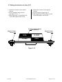
ICoT 5000
Smart Valve Positioner
Operating Manual
Westlock Controls Limited
22 Chapman Way
Royal Tunbridge Wells, Kent TN2 3EF England
Phone:+44 (0) 1892-516277 Fax: +44 (0) 1892-516279
10/31/02
Westlock Controls Corporation
280 Midland Avenue
Saddle Brook, NJ 07663
Phone: 201-794-7650 Fax: 201-794-0913
Tech-304/DWO 14195
Westlock Equipamentos de Controle Ltda.
Rua Sao Paulo, 291 - Alphaville
06465-130 Barueri, SP Brazil
Tel: 55-11-4191-0930 Fax: 55-11-4191-0931
Page 1 of 39
Table of Contents
Section 1 - Introduction
Page
1.1 Description of ICoT..........................................................................................
1.2 Principal of Operation.......................................................................................
1.3 Special Features................................................................................................
3
4
5-7
Section 2 - Ordering
2.1 ICoT 5000 Positioner Ordering Guide...................................................................... 7
Section 3 - Initial Setup
3.1 Mounting Positioner on a Rotary Actuator......................................................
3.2 Mounting Remote Positioner on a Rotary Actuator.........................................
3.3 Mounting Positioner on a Linear Actuator......................................................
3.4 Mounting Remote Positioner on a Linear Actuator.........................................
3.5 Pneumatic Connection.....................................................................................
3.6 Electrical Connection ......................................................................................
3.7 Setting Switches on Rotary ICoT.....................................................................
8-9
10-11
12-14
14-15
16
17
18
Section 4 - Calibration
4.1 Enter Calibration (Menu Level)......................................................................
4.2 Configure the Positioners Parameters.............................................................
4.3 Automatic Calibration.....................................................................................
4.4 Proceed to Exiting Calibration or Perform Advanced Calibration.................
4.5 Exiting Calibration.........................................................
4.6 Manual Override of Input Signal (Via On-Board Keypad)............................
4.7 Description of Menu’s....................................................................................
4.8 Description of Functions..................................................................................
19
19
20
20
21
21
22-23
23-25
Section 5 -Trouble Shooting
5.1 Preliminary Checks..........................................................................................
5.2 Common Problems...........................................................................................
26
27
Section 6 - Specifications .............................................................
28
Section 7 - Error Codes ............................................................................
29
Appendices
A. Procedure to Adjust Err 3 Setting ....................................................................
B. Procedure to Remove Display Board & Electronic Cannister..........................
C. Procedure to Check Transducer Operation ......................................................
D. Grounding Schematic ......................................................................................
E. Control Schematic for Wiring of Intrinsically Safe ICoT (WD-10836) ..........
F. Procedure to Reset the EEprom to factory Settings.........................................
G. Hart® Communicator Menu Flow Chart..........................................................
10/31/02
Tech-304/DWO 14195
30
31
32
33
34-37
38
39
Page 2 of 39
Section 1- Introduction
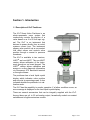
1.1 Description of ICoT Positioner
The ICoT Smart Valve Positioner is an
electro-pneumatic servo system that
continuously controls the position of a
valve based on a 4 to 20 mA input signal. The ICoT is an instrument that
derives its power directly from a control
systems current loop. The instrument
senses valve position via a non-contact
Hall effect sensor and controls valve
position through a current to pressure
transducer.
The ICoT is available in two versions,
HART® and non-HART. The non-HART
version allows calibration of the instrument through an on board keypad. The
HART® version allows calibration and
access to on-line diagnostic information
via Rosemount 275 hand-held terminal
or through software.
The positioner has a local liquid crystal
display which indicates valve position
and set-point in percentage open. It also
indicates whether the positioner is in calibration mode.
The ICoT has the capability to monitor operation. If a failure condition occurs, an
error message is displayed on the local liquid crystal display.
There are several accessories that can be integrally supplied with the ICoT.
Among these are a 4 to 20 mA analog output, hermetically sealed non-contact
switches and a fugitive emissions monitor.
10/31/02
Tech-304/DWO 14195
Page 3 of 39
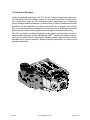
1.2 Principal of Operation
Unlike conventional positioners, the ICoT Smart Positioner feeds back valve position without the need for linkages, levers, or rotary and linear seals. Position sensing is performed totally by non-contacting means, permitting use of advanced
control strategies where knowledge of valve position is used in predictive and other
algorithms. By the integration of multiple components into a singular, cost efficient
unit, microprocessor-based intelligence can now be used to implement advanced
functions such as early warning diagnostics and fugitive emissions monitoring.
The ICoT positioner provides intelligence for the control valve through a microprocessor-based diagnostic system utilizing the HART® protocol. Accurate measurement of valve stem position, input signal, actuator pressure and travel time can be
recorded during normal operation, thereby providing information for control valve
signature generation.
10/31/02
Tech-304/DWO 14195
Page 4 of 39
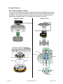
1.3 Special Features
NON-CONTACT POSITION FEEDBACK
Non-Contact Position Feedback
To provide consistently accurate performance information, all linkages, levers and
connecting rods, from the positioner to the control valve have been eliminated from
the design. Valve position sensing is performed totally by non-contacting means
based upon characterization of flux strength as a function of position.
Linear Valves
Rotary Valves
Sensor
Magnet
Magnet
Magnet
Actuator
Shaft
Magnet
Sensor
Valve
Stem
Magnet
Magnet
Sensor
10/31/02
Tech-304/DWO 14195
Page 5 of 39
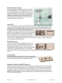
Remote Position Control
Since valve position feedback to the ICoT positioner
is accomplished by non-contacting means, the ICoT
has the unique ability to be mounted remotely (up to a
distance of 50 feet) from the device it is controlling. In
the event the control valve is located in either a high
vibration or extremely corrosive environment, the
non-contact position feedback feature allows for isolated placement of the positioner.
Local LCD
The ICoT positioner is supplied with HART® interface or a 3-button keypad interface. Both
versions are furnished with a 4-digit,.5”tall LCD, and allow for automated calibration of the
positioner. The local LCD provides a multitude of onsite diagnostic information. While the
valve is being controlled by the positioner, and the error signal is not zero, the displayed information will alternate between setpoint and position as a percentage.
Each value is displayed for a period of two seconds.
Once the setpoint and valve position agree to within
less than 0.5%, the display will only show position. The range of values displayed are from
0.0% to 100.0%. Displayed resolution is in 0.1% increments, however, internal calculations
are maintained at higher precision.
On-Board Sensors
The ICoT positioner has the capability to monitor its
operation. If an error or failure condition occurs, it will
be displayed on the local LCD, or if the positioner is
supplied with a HART® interface, the error codes will be
displayed on a hand held terminal or a PC maintenance station. Note: Error codes are denoted on a label affixed to the LCD flip-up protective
cover.
Local Keypad
All positioners are provided with a 3-button membrane keypad.The keypad is provided for zero and span adjustments, as
well as valve characterization and gain adjustments.
Intelligent Calibration (HART® Protocol)
The ICoT positioner responds to HART® commands for seeking the “valve closed”position
and assigns an instrument signal of 4 mA to this position. The counterpart of the operation
for a full open state is implemented next by setting the span value. Action reversal is also
configured. Additionally, provisions are made for altering internal servo loop tuning via the
HART® link. In this manner, positioner performance may be optimized with a wide combination of valves and actuators.
10/31/02
Tech-304/DWO 14195
Page 6 of 39
Negligible Bleed
Designed to consume the least possible amount of control air at steady state, the ICoT 5000
Series positioner can greatly reduce the air consumption of your process and reduce the
demand on instrument air compressors. To increase reliability, the ICoT employs a patented
lapped spool and floating sleeve design. This balanced construction relies on an air bearing
which eliminates any metal to metal contact.
Section 2 - Ordering
The ICoT positioner is designed to handle a wide range of control valve applications.
Please use the following ordering guide to help choose the ICoT positioner that best
suits the application.
2.1 ICoT 5000 Positioner Ordering Guide
CALIBRATION/COMMUNICATION
HOUSING MATERIAL
E
ENGINEERED RESIN
P POTENTIOMETER
K VIA ON BOARD KEYPAD
B BOTH HART & KEYPAD
MOUNTING
* SELECT OPTION P FOR THE 4100 SERIES
SELECT OPTION K FOR THE 4200 SERIES
SELECT OPTION H OR B FOR THE 4300
SERIES
0 NORMAL MTG
5 REMOTELY MTD
SWITCHES
0 NONE
1 ONE SPST (ROTARY POSITIONER ONLY)
2 TWO SPST (ROTARY POSITIONER ONLY)
ACTUATOR TYPE
1 LINEAR
3 ROTARY
OUTPUT OPTION
A NO TRANSMITTER
B 4-20mA ANALOG
SERIES
51 5100 SERIES-ICOT JUNIOR
(ANALOG POSITIONER)
52
5200 SERIES-KEYPAD ICOT
(SMART POSITIONER)
53
5300 SERIES-HART ICOT
(SMART POSITIONER)
5130 NI E HK A 0 B N
OUTPUT (STANDARD
ON SERIES 4100)
AIR PORTS
N 1/4” NPT
B 1/4” BSP
HAZARDOUS RATING
NI NON-INCENDIVE
IS INTRINSICALLY SAFE
CONDUIT ENTRY
PRESSURE
(ACTUATOR SUPPLY)
H 40-120 PSI
A ONE 1/2" NPT
B ONE M20
L 15-45 PSI
Note: When ordering a liner ICoT positioner, (option “1” for the third digit in the part
number) be prepared to supply the exact stroke length and fail direction of the application.
10/31/02
Tech-304/DWO 14195
Page 7 of 39
Section 3 Initial Setup
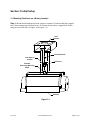
3.1 Mounting Positioner on a Rotary Actuator
Step 1. Mount bracket and inner beacon coupler to actuator. If actuator shaft has a tapped
hole, fasten using proper flat head screw. If actuator does not have a tapped hole, fasten
using set screws on side of coupler. (See Figure 3-1)
ICoT
Bracket
Flat Head Screw
Inner Beacon
Coupler
Set Screw
Actuator
Accessory Mounting
Shaft
Actuator
Figure 3-1
10/31/02
Tech-304/DWO 14195
Page 8 of 39
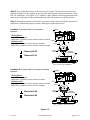
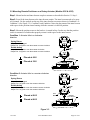
Step 2. Press fit the inner beacon to the inner beacon coupler. The inner beacon needs to be
properly oriented. Use the symbols on the top of the inner beacon to mount as shown in Condition 1 or Condition 2. (See Figure 3-2). Condition 1 and Condition 2 show the placement of the
inner beacon with respect to the positioner housing while the actuator is in the fail position.
Step 3. Mount the positioner to the bracket. As stated in Step 2 make sure that the positioner is
mounted in a fashion that properly orients it with respect to the inner beacon.
Condition 1: Actuator fails in a clockwise
direction.
Supply
Spring Return
Output Port 2 is plugged
Output Port 1 is piped to turn the actuator counter clockwise
Port 1
Double Acting
Output Port 2 is piped to turn the actuator clockwise
Output Port 1 is piped to turn the actuator counter clockwise
Port 2
Inner
Beacon
Placed at 6:00
Actuator
(In Fail Position)
Placed at 3:00
Condition 2: Actuator fails in a counter clockwise
direction.
Supply
Spring Return
Output Port 2 is plugged
Output Port 1 is piped to turn the actuator clockwise
Double Acting
Port 1
Output Port 2 is piped to turn the actuator counter clockwise
Output Port 1 is piped to turn the actuator clockwise
Port 2
Inner
Beacon
Placed at 9:00
Actuator
(In Fail Position)
Placed at 6:00
Figure 3-2
10/31/02
Tech-304/DWO 14195
Page 9 of 39
3.2 Mounting Remote Positioner on a Rotary Actuator (Models 4235 & 4335)
Step 1. Mount bracket and inner beacon coupler to actuator as described in Section 3.1 Step 1.
Step 2. Press fit the inner beacon to the inner beacon coupler. The inner beacon needs to be properly oriented. Use the symbols on the top of the inner beacon to mount as shown in Condition 1 or
Condition 2. (See Figure 3-3). Condition 1 and Condition 2 show the placement of the inner beacon
with respect to the position sensor housing while the actuator is in the fail position.
Step 3. Mount the position sensor to the bracket. As stated in Step 2 make sure that the position
sensor is mounted in a fashion that properly orients it with respect to the inner beacon.
Condition 1: Actuator fails in a clockwise
direction.
Position
Sensor
Spring Return
Output Port 2 is plugged
Output Port 1 is piped to turn the actuator counter clockwise
Double Acting
Conduit
Entry
Output Port 2 is piped to turn the actuator clockwise
Output Port 1 is piped to turn the actuator counter clockwise
Inner
Beacon
Placed at 6:00
Actuator
(In Fail Position)
Placed at 3:00
Condition 2: Actuator fails in a counter clockwise
direction.
Position
Sensor
Spring Return
Output Port 2 is plugged
Output Port 1 is piped to turn the actuator clockwise
Double Acting
Conduit
Entry
Output Port 2 is piped to turn the actuator counter clockwise
Output Port 1 is piped to turn the actuator clockwise
Inner
Beacon
Placed at 9:00
Actuator
(In Fail Position)
Placed at 6:00
Figure 3-3
10/31/02
Tech-304/DWO 14195
Page 10 of 39
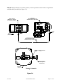
Step 4. Mount positioner at a remote location, wire the positioner sensor back to the positioner
using the cable provided (See Figure 3-4).
Positioner
(Mounted Remote from
Actuator at Users Discretion)
Position Sensor
(Mounted on Actuator
as Described in Step 3)
J3
J4B
J4A
TRANSDUCER
J1
J1
J6
LCD
TP1
TP2
J5
3/4 NPT
(F)
1/2 NPT
(F)
Actuator
(Top View)
(4) Conductor Cable
(Cut to Required Length
and Run Through Conduit)
(4) Conductor Shielded
Cable
8
7
6
5
HALL
EFFECT
SENSOR
4
3
2
1
SHIELD
BLACK
GREEN
RED
WHITE
Pin Connector
(To Display Board
of Positioner)
Positioner
Sensor
Wiring Schematic
Figure 3-4
10/31/02
Tech-304/DWO 14195
Page 11 of 39
3.3 Mounting Positioner on a Linear Actuator
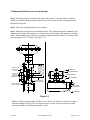
Step 1. Mount the magnet assembly to the stem of the actuator. A coupler block normally is
needed to extend the magnet assembly outside the yoke area and into the sensing range of the
magnetic pick-up unit.
Step 2. Fasten the mounting bracket to the actuator.
Full
Stroke
ICoT Assembly
Housing
Centerline of
Magnetic
Pick-Up Unit
(Position Sensor)
Stroke/2
Lower Limit of Travel
Upper Limit of Travel
1/16”
Magnet Assembly
Location of Centerline
Step 3. Mount the positioner to the mounting bracket. The positioner should be mounted so the
magnetic pick-up unit of the positioner is centered between the limits of the magnetic assembly’s
stroke. After mounting the positioner, the magnet assembly should be within 1/8” from the back
of the positioner (1/16” is ideal), (See Figure 3-5).
Stroke/2
Actuator Yoke
Actuators Split Block
Magnet Assembly
Mounting Bracket
Actuator Split Block
(At Upper Limit of Travel)
.062
Actuator
Centerline
Actuator Split Block
(At Lower Limit of Travel)
Magnetic Pick-Up
Unit (Position Sensor)
ICoT Assembly
Figure 3-5
Note: For Fisher actuators model 657 & 667 sizes 34 thru 70, Westlock Controls can supply a
slotted mounting kit design. This will allow the user to easily center the positioner sensor
between the limits of the magnet assembly’s stroke.
10/31/02
Tech-304/DWO 14195
Page 12 of 39
Magnet Assembly
at Upper Limit
of Travel
Actuator
Yoke
Upper Limit
of Travel Mark
Midpoint
of Travel Mark
ICoT
Lower Limit
of Travel Mark
Magnet Assembly
at Lower Limit
of Travel
Figure 3-6
To Center the Positioner
1. Stroke the actuator to its upper limit and place a mark on the actuator’s yoke that lines up
with the red arrow on the magnet assembly.
2. Stroke the actuator to its lower limit and place a mark on the actuator’s yoke that lines up
with the red arrow on the magnet assembly.
3. Place a third mark on the yoke centered between the upper and lower limit marks.
4. Lastly, mount the positioner to the bracket so that the positioner sensor (nose) of the ICoT
lines up with the midpoint mark. (See Figure 3-6).
10/31/02
Tech-304/DWO 14195
Page 13 of 39
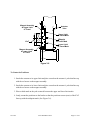
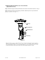
3.4 Mounting Remote Positioner on a Linear Actuator
(Models 4215 & 4315)
Step 1. Mount the magnet assembly and bracket to the actuator as described in Section 3.3 Step 1.
Step 2. Mount the position sensor housing so that the conduit entry faces away from the diaphragm or cylinder. (See Figure 3-7)
Actuator
Mounting Bracket
Position Sensor
Conduit Entry
Figure 3-7
Note: For Fisher actuators model 657 & 667 sizes 34 thru 70, Westlock Controls supplies a
slotted mounting kit design, to ease the mounting process. This will allow the user to easily
center the positioner sensor between the limits of the magnet assembly’s stroke.
10/31/02
Tech-304/DWO 14195
Page 14 of 39
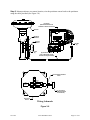
Step 2. Mount positioner at a remote location, wire the positioner sensor back to the positioner
using the cable provided (See Figure 3-8).
Positioner
(Mounted Remote from
Actuator at Users Discretion)
Actuator
J3
J4B
J4A
TRANSDUCER
J1
J1
J6
LCD
TP1
Mounting
Bracket
TP2
J5
Position
Sensor
1/2 NPT
(F)
3/4 NPT
(F)
(4) Conductor Cable
(Cut to Required Length
and Run Through Conduit)
(4) Conductor Shielded
Cable
8
7
6
5
HALL
EFFECT
SENSOR
4
3
2
1
SHIELD
BLACK
GREEN
RED
WHITE
Pin Connector
(To Display Board
of Positioner)
Positioner
Sensor
Wiring Schematic
Figure 3-8
10/31/02
Tech-304/DWO 14195
Page 15 of 39
3.5 Pneumatic Connection
MOUNTING INSTRUCTIONS
Single Acting Actuator (Spring Return):
For single acting actuators Outlet Port 2 is to
be plugged. Outlet Port 1 is to be piped to the
actuator inlet port that acts against the
spring. (Increasing signal causes pressure to
increase in Outlet Port 1 of the positioner).
Double Acting Actuator (Double Return):
For double acting actuators Outlet Port 2 is
piped to drive the actuator towards the fail
position. Outlet Port 1 is piped to drive the
actuator away from the fail position. (Increasing signal causes pressure to increase in Outlet
Port 1 of the positioner and pressure to
decrease in Outlet Port 2 of the positioner).
Note: Air supply to the positioner must be
clean, dry, oil free instrument air per ISA-S7.3.
Maximum supply pressure is 120 psi. All
pneumatic connections are 1/4” NPT.
Inlet Port
Outlet Port 1
Outlet Port 2
Inlet Port
Gage
Outlet Port 1
Gage
1. Single Acting/Spring Return (Plug Outlet Port 2) increasing signal causes pressure to increase in Outlet Port 1.
2. Double Acting/Double Return (Pipe Outlet Port 2 to drive
actuator towards the desired failure direction) increasing
signal causes pressure to decrease in Outlet Port 2 and
pressure to increase in Outlet Port 1.
Notes:
1. On loss of power pressure fails to Outlet Port 2.
Figure 3-9
10/31/02
Tech-304/DWO 14195
Page 16 of 39
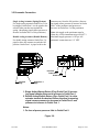
3.6 Electrical Connection
Slide Off Terminal Strip
from Keypad assembly
1. Remove positioner cover.
2. Locate terminal strip and carefully disconnect
(slide off).
3. Connect the 4 to 20 mA loop signal to terminal points marked (+) and (-). See figure 3-10
for a wiring schematic.
4. If the positioner was ordered with an analog
output, connect output wiring to terminal
points 5 & 6, (Polarities Shown Below). The
4 to 20mA analog output requires an external
24 volt DC power supply.
5. If the positioner was ordered with switches,
connect to the switches at terminal points 1
thru 4, as shown in Figure 3-10.
6. After all connections have been made reconnect the terminal strip and replace positioner
cover.
BLK
WHT
BLK
WHT
J4A
SWITCH 1
(OPTIONAL)
J4B
2
1
2
+
+
-
2
3
4
5
6
-
+
1
1
DISPLAY BOARD
COM
N/O
COM
N/O
}
}
}
}
ANALOG
INPUT
ANALOG
OUTPUT
SWITCH 2
(OPTIONAL)
PRESSURE SWITCH (HART)
SWITCH 2
OR Fugitive Emissions EM-300
(OPTIONAL)
(OPTIONAL)
SWITCH 1
(OPTIONAL)
Non-Incendive
ICoT
Figure 3-10
10/31/02
Tech-304/DWO 14195
Page 17 of 39
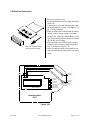
3.7 Setting of switches on a rotary ICoT
1. Operate the actuator to the desired
extreme.
2. Loosen magnetic trigger bolt #1.
(See Figure 3-12)
3. Slide trigger bolt #1 beneath the first
switch and tighten with wrench.
4. Operate the actuator to the opposite
extreme.
5. Loosen magnetic trigger bolt #2.
6. Slide trigger bolt #2 beneath the second
switch and tighten with wrench.
Position Feedback Monitor
(Inner Beacon)
Magnetic Trigger
Bolt #1
Magnetic Trigger
Bolt #2
OPEN
CLOSED
CLOSED
OPEN
Figure 3-12
10/31/02
Tech-304/DWO 14195
Page 18 of 39
Section 4 - Calibration
The ICoT positioner has an on-board help menu that can be accessed by pressing the Cal button and
either arrow button simultaneously, anytime during calibration.
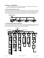
4.1 Enter Calibration (Menu Level)
Enter the calibration routine by pressing and holding the CAL button. Continue to hold the CAL button until
ACAL appears on the LCD. ACAL (Auto Cal Menu) is the first of four menus. By pressing the down arrow
button you can cycle through the four menus. The remaining three menus are MCAL (Manual Cal Menu),
Cofg (Configuration Menu), Stro (Manual Position Override Menu). The menu level is shown below.
Normal Operation
(“OK” Displayed on LCD)
Press & Hold CAL
key until “ACAL”
appears on display
Up
Arrow
Up
Arrow
Down
Arrow
ACAL
Down
Arrow
MCAL
(See Section 4.3)
Up
Arrow
Up
Arrow
Down
Arrow
(See Section 4.4)
Down
Arrow
Cofg
Stro
(See Section 4.6)
(See Section 4.2)
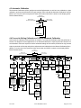
4.2 Configure the Positioners Parameters
From the menu level press the down arrow button until the Cofg (Configuration Menu) is shown on the display (Configuration Routine Shown Below). Enter this menu and change any of the parameters, if other
than the factory settings are needed. The factory settings are highlighted.
Up Arrow
(Exit Calibration)
Down Arrow
(From Previous Menu)
Down Arrow
(To Next Menu)
Cofg
CAL
Up Arrow
Up Arrow
Flow
CAL
Down
Arrow
Type
Down
Arrow
FLOP
CAL
CAL
Up Arrow
Up Arrow
Down
Arrow
OPSP
CAL
Up Arrow
Down
Arrow
CLSP
CAL
Up Arrow
Down
Arrow
Down
Arrow
EDb
CAL
CAL
Lin
Lin
OFF
Linear
Flow
Linear
Valve
Fail
Closed
CAL
CAL
Down
Down
OPn
Quick
Opening
Down
CAL
CAL
Down
rot
Rotary
Valve
Down
On
Fail
Open
Use UP
& Down
Arrows
to Select
Open
Speed
01=Slow
05=Fast
OFF
Deadband
at ? ?.5%
Down
Down
ON
CAL
CAL
Down
CAL
Use UP
& Down
Arrows
to Select
Close
Speed
01=Slow
05=Fast
CAL
Use UP
& Down
Arrows
to Adjust
Deadband
CAL
EP
CAL
Equal
Percentage
Down
10/31/02
CAL
Tech-304/DWO 14195
Page 19 of 39
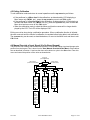
4.3 Automatic Calibration
The Automatic Calibration (ACAL) performs several self-adjustments, as well as a zero calibration, a span
calibration, and tunes the positioners PID gain settings. Enter and start the Automatic Calibration from the
Menu level. From the menu level press the down arrow button until ACAL is shown on the display (ACAL
Routine Shown Below).
Up Arrow
(Exit Calibration)
Down Arrow
(From Previous Menu)
Down Arrow
(To Next Menu)
ACAL
Set 12mA
Press CAL Key
Auto Calibrate
1. Sensor Cal
2. Trnd
3. Lo
4. Hi
5. Auto PID
4.4 Proceed to Exiting Calibration or Perform Advanced Calibration
At this point the calibration of the positioner is complete. The Automatic Calibration that was performed in
Section 3 is adequate for most applications. If no advanced calibration is required proceed to Section 5 to
exit calibration. If the user requires to use the advanced settings to fine tune the positioner he may proceed
with the remainder of this step and perform adjustments and calibrations in the Manual Calibration Menu
(MCAL). From the menu level press the down arrow button until MCAL is shown on the display (MCAL
Routine shown below).
Up Arrow
(Exit Calibration)
Down Arrow
(From Previous Menu)
-LoPress CAL Key
Up Arrow
Down
Arrow
Up Arrow
CAL
Down
Arrow
-HiPress CAL Key
Down Arrow
(To Next Menu)
MCAL
Down
Arrow
Up Arrow
Up Arrow
PID
Down
Arrow
Snsr
Down
Arrow
Set 12 mA
Press CAL Key
Press CAL Key
Trnd
Set 12 mA
Press CAL Key
Up Arrow
Down
Arrow
-mA-
Press CAL Key
Up Arrow
Down
Arrow
Xmr
Down
Arrow
Press CAL Key
Down
Arrow
Set mA
Set mA
for Fail Position
for Fail Position
Press CAL Key
Press CAL Key
AUT
MAN
Press CAL Key
Press CAL Key
Sensor
Calibration
Transducer
Calibration
Set 4.0 mA
Press CAL Key
Zero
Calibration
Automatic
Optional:
Value & Use
Up & Down
Arrows to Enter The
Present Zero Value
PCAL
PID Routine
Adjust using
Up & Down
Arrow Keys
(1-20)
Span
Calibration
Press CAL Key
ICAL
OFF
Read Transmitter
Down
Arrow
Down
Arrow
ICAL
ON
Press CAL Key
Set 20.0 mA
Press CAL Key
Use Up & Down
Arrows to Enter
the Desired Zero
Current, Typically
4.0 mA
Press CAL Key
Optional:
Select Arbitrary
Zero Using Up
& Down Arrow
Keys
Select Arbitrary
Span Using Up
& Down Arrow
Keys
Press CAL Key
When Complete
Press CAL Key
When Complete
Press CAL Key
Read Transmitter
Press CAL Key
ICAL
Adjust using
Up & Down
Arrow Keys
(1-5)
Press CAL Key
DCAL
Adjust using
Up & Down
Arrow Keys
(1-20)
Value & Use
Up & Down
Arrows to Enter The
Present Span Value
Press CAL Key
Use Up & Down
Arrows to Enter
the Desired Span
Current, Typically
20.0 mA
Press CAL Key
When Complete
Press CAL Key
When Complete
10/31/02
Tech-304/DWO 14195
Page 20 of 39
4.5 Exiting Calibration
To exit calibration mode and return to normal operation use the up arrow key as follows:
• If the positioner is at Menu level in the calibration, as determined by LCD displaying a
Menu name only (MCAL, etc.), press the up arrow key once to exit CAL mode.
• If the positioner is at function level in the calibration, as determined by LCD displaying a
function and Menu name only (MCAL Lo, etc.), press the up arrow key once to enter the
Menu level and once more to exit CAL mode.
• When the calibration mode is exited the Menu and function names will no longer be displayed by the LCD. The LCD will be displayed “OK”.
Exiting can not be done during a calibration procedure. When a calibration function is initiated,
the user must wait until the function’s calibration is complete before being able to exit calibration.
The up arrow key can be used, as described above, to move to the Menu level and then to exit
CAL mode.
4.6 Manual Override of Input Signal (Via On-Board Keypad)
The positioner has a feature which allows the operator to override the analog signal and change valve
position from the keypad. This is done from the Stro (Manual Override-Stroke Menu). Enter calibration as described in section 4.1 and use the down arrow button to cycle to the Stro menu. Enter this
menu and control the position of the valve as shown below.
Up Arrow
(Exit Calibration)
Down Arrow
(From Previous Menu)
Down Arrow
(To Next Menu)
Stro
CAL
Up
Up
Up
Adjs
CAL
Fast
Move
Press Up
or Down
Arrow
one time
valve
moves
5%
CAL
Down
Arrow
OP
Down
Arrow
CLs
CAL
Valve
CAL
Use Up
& Down
can
move
valve
Slowly
Valve
Closed
Use Up
& Down
can
move
valve
Slowly
CAL
CAL
Full Open
Down
Arrow
Slow
Move
Press &
Hold Up
or Down
Arrow
valve will
move
slowly
CAL
10/31/02
Tech-304/DWO 14195
Page 21 of 39
4.7 Description of Menu’s
The calibration functions of the positioner is organized into the following four menus:
Menus
• Menu 1: ACAL (Automatic Calibration)
• Menu 2: MCAL (Manual Calibration)
• Menu 3: Cofg (Configuration)
• Menu 4: Stro (Manual Override of Input Signal)
Menu desciptions are as follows:
Menu 1: ACAL (Automatic Calibration)
Entering this menu allows you to initiate an approximately seven minute self-calibration function.
The positioner will automatically enter digital control mode and perform a shallow (input current
independent) calibration in the following sequence:
Function
1. -Snsr- Sensor Calibration
2. -Trnd- Transducer Calibration
3. -Lo- Low (Zero) Calibration
4. -Hi- High (Span) Calibration
5. -Auto- Automatic PID Tuning
Menu 2: MCAL (Manual Calibration)
Entering this menu allows you access to the following four calibration functions via the keypad:
1. -Lo- Low (Zero) Calibration
2. -Hi- High (Span) Calibration
3. -PID- Proportional, Integral and Derivative Gain Adjustment
4. -Snsr- Sensor Calibration
5. -Trnd- Transducer Calibration
6. -mA- Milliampere Calibration
7. -Xmr- Transmitter Calibration
10/31/02
Tech-304/DWO 14195
Page 22 of 39
Menu 3: Cofg (Configuration)
Entering this menu allows you access to the following five configuration functions via the keypad:
1. -Flow- Positioner Output Flow Characteristics
2. -Type- Positioner Recognition of Magnetic Feedback, Rotary or Linear
3. -Flop- Positioner Fail Position, Open or Closed
4. -OPSP- Positioner Opening Speed Adjustment
5. -CLSP- Positioner Opening Speed Adjustment
These functions allow display, speed and valve characteristic changes from standard factory settings.
Menu 4: Stro (Manual Override of Input Signal)
Entering this menu allows you access to the following three stroking functions via the keypad:
1. -Adjs- Adjustment of Positioner to Any Position Using Keypad Arrows
2. -OP- Open, Sets the Valve to the Full Open Position
3. -CLs- Close, Sets the Valve to the Full Closed Position
These functions set the positioner to digital control mode (input current independent) and
therefore allow override of the control signal.
4.8 Description of Functions
LO
This function serves to set the fail position of the actuator/valve. Initially during this calibration the valve is driven to the fail position (hard stop). The user will notice full pressure to
Outlet Port 2 and zero pressure to Outlet Port 1. After a short period of time pressure will
increase in Outlet Port 1 and the valve will be driven to the fully energized position and then
back to the fail position. After approximately 30 seconds pressure will again increase in Outlet Port 1 and the valve will be driven off of the hard stop (approx. 10% of full travel), and
then driven back to the hard stop. The calibration is making note of the torques required to
fully seat and un-seat the valve from the hard stop. At this point the user has the option to
select the hard stop as low (zero) position or to select an arbitrary position as low (zero)
position.
HI
This function serves to set the fully energized (full travel) position of the actuator/valve. initially during this calibration the valve is driven to the fully energized (full travel) position
(hard stop). The user will notice full pressure to Outlet Port 1 and zero pressure to Outlet
Port 2. After a short period of time pressure will increase in Outlet Port 2 and will be driven
off of the hard stop (approx. 10% of full travel), and then driven back to the hard stop. The
calibration is making note of the torques required to fully seat and un-seat the valve from a
hard stop. At this point the user has the option to select the hard stop as the high (span)
position. or to select an arbitrary position as the high (span) position.
10/31/02
Tech-304/DWO 14195
Page 23 of 39
PID
The PID function allows the user to enter or change the PID settings of the positioner. This
function is most often used to fine tune the PID values obtained from the automatic calibration function (ACAL). This function will allow the user to optimize the dynamic response of
the positioner with respect to speed of response, overshoot and percent error by varying the
appropriate gain settings.The Proportional (PCAL) and Derivative (DCAL) gain settings
can be varied incrementally on a scale from 1-20. The Integral (ICAL) gain setting can be
varied incrementally on a scale from 1-5. The larger the number the higher the gain setting.
Snsr
The sensor calibration is a self adjustment that sets the positoners Hall-Effect circuitry. This
is automatically done during the ACAL (Automatic Calibration) routine. The sensor calibration also shows up under the MCAL menu. This calibration only needs to be performed
under the MCAL routine when the positioner is set-up on a new application and only if the
ACAL routine is not performed.
trnd
The purpose of this function is to calibrate the positioner’s transducer. The transducer is
calibrated on all new positioners at the factory, therefor this procedure does not need to be
performed for a new positioner. Perform this calibration function only if a replacement transducer or electronic canister was installed in the positioner.
-mA-
This routine calibrates the positioner’s electronics to recognizing input current. This is done
using 4.0 mA and 20.0 mA as reference points. If exactly 4.0 mA or 20.0 mA can not be
given as inputs, the user can adjust the positioners values to the input using the arrow buttons.
Xmr
This routine calibrates the positioner’s transmitter. The transmitter calibration does not
require the user to change the input current, although it does require the user to be able to
read the transmitter’s value in mA. For each, the zero and span, the user is first prompted to
enter the value that the transmitter is presently at. This is done by using the up and down
arrow buttons. The user is then prompted to enter the desired transmitter output (typically
4.0 mA for zero and 20.0 mA for span). The positioner then calculates the difference
between the present and the desired output currents (for zero and span) and uses the differential to adjust the transmitter accordingly.
Flow
This function allows for the setting of the flow characteristic of the positioner (not to be confused with the flow characteristic of the valve). The options are Lin (Linear), EP (Equal
Percentage) and Opn (Quick Opening). A Lin (Linear) positioner characteristic duplicates
the inherent characteristic of the valve and is the most often used setting.
Type
This function configures the positioner for the type of valve. The options are rot
(Rotary) and lin (Linear). This setting needs to be done in order to configure the positioner to recognize the type of magnetic feedback being given to the positioner.
FLOP
This function allows the user to configure the positioner to match the failure method of the
valve/actuator. The options are “off” or “on”. The “off” option is for fail closed applications
and the “on”option is for fail open application. When “off” is chosen the LCD will read 0%
at the zero (Lo Calibration) and 100% at the span (Hi Calibration). When “on” is chosen
the LCD will read 100% at the zero (Lo Calibration) and 0% at the span (Hi Calibration).
10/31/02
Tech-304/DWO 14195
Page 24 of 39
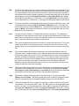
OPSP
This function allows for the setting of the opening speed of the actuator/valve. The range is
1 thru 5. Setting 5 is the fastest opening speed and setting 1 is the slowest opening speed.
Setting
CLSP
Approx.% Dynamic Speed
5
4
100%
80%
3
60%
2
40%
1
20%
This function allows for the setting of the closing speed of the actuator/valve. The range is 1
thru 5. Setting 5 is the fastest closing speed and setting 1 is the slowest closing speed.
Setting
Approx.% Dynamic Speed
5
4
100%
80%
3
60%
2
40%
1
20%
EDb
This feature configures the positioner’s operating deadband. The configuration options are “off”
and “on”. The positioner is factory set as “off”. When the deadband feature is “off” it operates with nominal value of ± 0.3% of full scale for deadband. When the feature is turned
“on”, the deadband can be set using the up and down arrow buttons to a value from 1 to
20. The value 1 (lowest deadband when turned “on”) has a deadband range of 1%,
which is equivalent to a deadband of ± 0.5%. The value 20 (highest deadband value) has
a range of 20%, which is equivalent to a deadband of ± 10%.
Adjs
This function allows for the adjustment of the positioner to any position via the keypad. This
function places the positioner in digital control mode (input current independent) and
therefor allows override of the control signal. Within this function there are Fast and Slow
move modes. In Fast move mode the valve is opened or closed in 5% increments via the
keypad. In Slow move mode the valve is opened or closed slowly via the keypad.
OP
This function sets the valve to the fully energized position via the keypad (Outlet Port 1 =
Supply psi & Outlet Port 2 = 0 psi). This function places the positioner in digital control
mode (input current independent) and therefor allows override of the control signal.
CLs
This function sets the valve to the fully denergized position via the keypad (Outlet Port 1 =
0 psi & Outlet Port 2 = Supply psi). This function places the positioner in digital control
mode (input current independent) and therefor allows override of the control signal.
10/31/02
Tech-304/DWO 14195
Page 25 of 39
Section 5 - Trouble Shooting
5.1 Preliminary Checks
Before operating the positioner check the following:
1. Voltage
The positioner requires a 24 volt DC (nominal), 4-20 mA current loop.
2. Electrical Connection
Check the polarity of the 4-20 mA current
loop. The ICoT terminal strip visually designates the positive and negative terminal
points for connection with a “+” and “-”,
respectively.
3. Pneumatic Connection
Single Acting: Output port 1 should be piped
to drive the actuator away from the valves
fail position. Output port 2 should be
plugged. (See Section 3.3)
Double Acting: Outport port 1 should be
piped to drive the actuator away from the
valves fail position. Output port 2 should be
piped to drive the actuator towards the
valves fail position. (See Section 3.3)
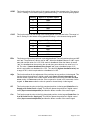
Polarities of Magnetic Feedback Assemblies
(For Linear ICoT Positioners)
S
N
N
S
N
S
S
N
FAIL-DOWN
FAIL-UP
(Actuator Fails in Direction A)
(Actuator Fails in Direction B)
Direction B
Direction A
4. Magnetic feedback to the Positioner
Rotary Positioner: The magnetic beacon
should be set in the proper orientation, based
on the direction of failure. (See Section 3.1)
Linear Positioner: The magnetic assembly
supplied with the positioner should correspond to the stroke length and failure direction of the actuator. To make sure you have
the appropriate magnet assembly, check the
part. The stroke length and failure direction
should be printed on the part. On older
ICoTs the magnet assembly is not printed
with this information, although there should
be a serial number. Contact the factory with
the serial number to verify that it is correctly
matched to the actuator. (See Figure 5-1 &
Figure 5-2).
Figure 5-1
"A"
STROKE LENGTH OF
ACTUATOR/VALVE
DIM
"A"
MAGNET ASSY'
PART#
GREATER THAN 0.5" UP TO 1.0"
2.5
SW-30057
GREATER THAN 1.0" UP TO 1.5"
3.0
SW-30056
GREATER THAN 1.5" UP TO 2.0"
3.5
SW-30055
GREATER THAN 2.0" UP TO 2.5"
4.0
SW-30054
GREATER THAN 2.5" UP TO 3.0"
4.5
SW-30053
Figure 5-2
10/31/02
Tech-304/DWO 14195
Page 26 of 39
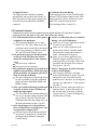
5. Supply Pressure
The supply pressure should be regulated
appropriately with regard to the actuator. If
there is question as to the proper supply pressure, the actuator manufacturer should be
contacted.
6. Positioner Pressure Rating
If the supply pressure is above 40 PSI a high
pressure ICoT positioner must be used. If the
supply pressure is below 40 PSI a low pressure ICoT positioner must be used.
(See Ordering Guide - Section 2.1)
5.2 Common Problems
Listed here are some common problems encountered with the ICoT positioner. Possible
causes are given and steps to help rectify the problem are offered.
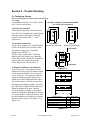
1. The LCD remains blank even after power 6. An Err 6 (Calibration Error) is returned
is applied to the positioner.
during a Lo or Hi Calibration.
In the case of a rotary application, the beaThe positioner should be given a minicon may be mis-oriented.
mum of 14 VDC. The voltage across the
In the case of a rotary application, the
positioner can be checked by removing the
actuator may not have enough rotation.
cover and connecting a voltmeter across
The positioner requires the actuator to
TP1 and TP2 on the display board.
stroke a minimum of 45 degrees.
2. The positioner has power but the position
In the case of a linear application, the
as shown on the LCD does not seem to
feedback magnet assembly needs to be
match the actual position of the actuator/
ordered specific to the stroke of the actuavalve.
tor and the fail direction of the actuator.
May need to be calibrated.
(See figure 5-1 & 5-2).
Beacon may be mis-oriented.
3. The positioner is properly set-up, and air is 7. An Err 5 (Integrator Overflow) message
is shown on the display.
applied to the positioner. When powering
up the positioner, the actuator goes into a
This messages indicates a deviation
state of constant oscillation.
between position and set-point. This error
The gain settings are to high for the actuamessage does not clear itself after the
tor/valve assembly. Enter the calibration
problem ceases, therefore, try clearing the
mode and reduce the PCAL, ICAL and
message. See Appendix A.1 “Procedure to
DCAL settings.
Clear Err 5”
4. After a successful calibration, position and
If the Err 5 returns, make sure all the preset point as shown on the LCD does not
liminary checks, as described earlier in
match the input signal.
this section, have been made. If still the
The flow characteristic during calibration
cause for the Err 5 can not be diagnosed,
was set to equal percentage or quick opencall the factory for help.
ing, not linear. If linear is desired enter
calibration and make this change (See Calibration Instructions section 4.1 & 4.2).
5. After removing power to the positioner
there is full pressure to output port 1 and
zero pressure to output port 2.
On loss of power the positioner fails full
air pressure to output port 2. If this does
not happen the positioner is damaged.
Contact factory.
10/31/02
Tech-304/DWO 14195
Page 27 of 39
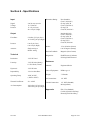
Section 6 - Specifications
Hazardous Rating:
Input
Signal:
Voltage:
Pressure:
4 to 20 mA, two wire
12.3 Volts DC
15 - 45 psi (Low)
40 - 120 psi: (High)
Intrinsically Safe
Class I, Division 1,
Groups A,B,C,D
Class II, Division 1,
Groups E,F,G
Class III, Division 1
Output
Flow Rate:
8.0 scfm @ 25 psi (Low)
16.2 scfm @ 90 psi (High)
Pressure:
0 to 45 psi (Low)
0 to 120 psi (High)
Actuator:
Single Acting or
Double Acting
Technical
Resolution:
.2% Full Travel
Linearity:
.5% Full Scale (Rotary)
1% Full Scale (Linear)
Hysteresis:
.2% Full Scale
Repeatability:
.2% Over One Hour
Operating Temp:
-40°C to 85°C
(-40°F to 185°F)
Thermal Coefficient:
2% / 100°C
Air Consumption:
.003 scfm @ 25 psi (Low)
.008 scfm @ 90 psi (High)
10/31/02
Non-Incendive,
Class I, Division 2,
Groups A,B,C,D
Class II, Division 2,
Groups F,G
Class III, Division 2
Stroke:
.25 to 24 inches (Linear)
0 to 95 Degrees (Rotary)
Position Feedback:
Magnetic (Non-Contact)
Diagnostics:
HART Protocol, Software
Utilizing HART Protocol
Enclosure
Material:
Engineered Resin
Class of Equipment:
NEMA type 4
Weight:
7.2 Pounds
Air Connections:
1/4” NPT
Conduit Connection:
1/2” NPT (Standard)
M20 (Optional)
Approvals
FM, CSA (Standard)
Cenelec (Special Label Req.)
Kema (Special Label Req.)
Tech-304/DWO 14195
Page 28 of 39
Section 7 - Error Codes
Err 3 (Error 3)
Low Input Pressure or Clogged Filter
Err 5 (Error 5)
Intergrator Overflow - Position of actuator does not
match setpoint of positioner
Err 6 (Error 6)
Calibration Error - Positioner could not successfully
perform calibration
ALR (Alert 3)
Valve position is not being maintained within the
deadband range. The deadband range (EDb) is set
from the configuration menu during calibration (Section 4). The EDb must be set to other then zero (0) to
enable the Alert 3 message.
10/31/02
Tech-304/DWO 14195
Page 29 of 39
Appendix A
Procedure to Adjust the Error 3 Setting
Note: The error 3 message is pre-set from the factory. For a low pressure positioner it
is set to 15 psi and for a high pressure positioner it is set at 55 psi. If these settings
come out of calibration or if it is necessary to change these settings, the following
instructions can be followed.
1. Before adjusting the Error 3 setting the positioner must be mounted and set-up. See section 3 of this manual.
2. To adjust the setting of the Error 3 message to indicate low input pressure, there is an
adjustment screw located on the top of the transducer. (See Figure Below)
3. To set the Error 3 for an explicit pressure value, loosen the lock nut on the adjustment
screw and gently turn the screw clockwise as far as it will go. Do not force the screw past
its limit or the Error 3 diaphragm assembly may be damaged.
4. Regulate the supply pressure to the pressure you would like to set as a low input pressure
flag.
5. Turn the adjustment screw slowly counter-clockwise to the point where the Err 3 message
appears on from the display.
6. Set this point by tightening the lock nut. Be careful not to effect the adjustment screw setting.
7. Re-regulate the supply air to the normal operating pressure.
Error 3
Adjustment Screw
(With Locknut)
Transducer
10/31/02
Tech-304/DWO 14195
Page 30 of 39
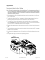
Appendix B
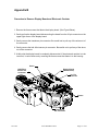
Procedure to Remove Display Board and Electronic Canister
1. Remove the three screws that fasten the display board. (See Figure Below).
2. Gently pull up the display board disconnecting the board from the 30-pin connector on the
upper right corner of the display board.
3. Gently remove the transducer pin connector. Be careful not to pull any of the wires out of
the connector.
4. Gently remove the hall effect sensor pin connector. Be careful not to pull any of the wires
out of the connector.
5. At this point the display board is completely disconnected. If the electronic canister is to be
removed, it can be done so by removing the three screws that fasten it to the housing.
Screw
Display Board
(Shaded Area)
Hall Effect
Sensor Pin
Connector
30 - Pin
Connector
Screws
Transducer
Pin Connector
10/31/02
Tech-304/DWO 14195
Page 31 of 39
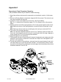
Appendix C
Procedure to Check Transducer Operation
(This procedure should only be used for trouble shooting)
1. Mount the positioner and connect the pneumatics as described in section 3 of this man-
ual.
2. Remove the Display Board as described in Appendix B of this manual. The electronic canister does not need to be removed.
3. Locate Pin 2 & Pin 4 on transducer pin connector. (See Figure Below)
Ref.: Pin 1 is furthest from the pressure gages, Pin 10 is nearest to the to the pressure
gages.
4. Connect positive lead of the signal generator to Pin 2 and connect negative lead to Pin 4.
Note: Make sure power on the signal generator is turned off before connecting it to the
pins.
Note: Make sure the two leads are not shorting by both coming in contact with Pin 3.
5. Turn on the 4-20 mA signal generator.
Note: The transducer operates between 0 and 3.3 mA. Therefore, make sure when turning on the current supply’s power the current is turned down within this range. Applying a
current greater then 3.3 mA can damage the transducer.
6. Apply the supply air to the positioner.
7. The transducer consists of a spool that will channel air between the two output ports of the
positioner. As the current is raised air is removed from Output Port 2 and applied to Output Port 1 of the positioner.
8. To check the operation of the positioner, raise and lower the current between 0 and 4 mA.
This should allow you to open and close the actuator. You should also be able to control
the position of the actuator by adjusting the current supply at an intermediary (idle) current
somewhere between 0 and 3.3 mA.
To Pin 2
(Red +)
To Pin 4
(Black -)
4-20 mA
Signal
Generator
* (Do Not Exceed
3.3 mA)
10/31/02
Tech-304/DWO 14195
Page 32 of 39
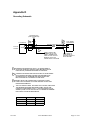
Appendix D
Grounding Schematic
{
TO HPORT MUX
(HART INTERFACE)
PLC OR DCS
4-20 mA
OUTPUT
1
2
2
TWISTED SHIELDED PAIR
+
-
ICOT SMART
POSITIONER
+
-
SHLD
3
SHIELD SHOULD BE
CONNECTED TO THE
SHIELD TERMINATION
POINT OF THE OUTPUT
MODULE OR TO THE
POWER SUPPLY GROUND
1
CONNECTION FROM DCS OR PLC TO POSITIONER IS
20 GAUGE SHIELDED TWISTED PAIR (BELDEN 8762 OR
EQUIVALENT). MAXIMUM DISTANCE IS 5000 FEET.
2
CONNECTION FROM HART MULTIPLEXER TO POSITIONER
IS 20 GAUGE SHIELDED TWISTED PAIR (BELDEN 8762
OR EQUIVALENT). MAXIMUM DISTANCE FROM HART
MULTIPLEXER TO POSITIONER IS 6000 FEET.
3
SHIELD SHALL BE CONNECTED TO GROUND AT ONE
POINT ONLY IN ORDER TO AVOID GROUND LOOPS AND
NOISE INTERFERENCE.
TAPE SHIELD &
DRAIN WIRE TO
PREVENT CONTACT
WITH GROUND
4. THE FOLLOWING TABLE, PER IEEE STD 518-1982, INDICATES
THE MINIMUM DISTANCE BETWEEN CABLE TRAYS AND
CONDUITS CONTAINING LEVEL 1 (THIS INCLUDES 4-20 mA
SIGNALS) AND 120 VAC OR 480 VAC, IN ORDER TO MINIMIZE
ELECTRICAL NOISE INTERFERENCE.
RACEWAY
480 VAC
TRAY
26”
TRAY-CONDUIT
18”
CONDUIT
12”
10/31/02
120 VAC
6”
4”
3”
Tech-304/DWO 14195
Page 33 of 39
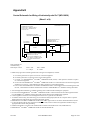
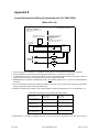
Appendix E
Control Schematic for Wiring of Intrinsically safe ICoT (WD-10836)
(Sheet 1 of 4)
NONHAZARDOUS LOCATION
HAZARDOUS LOCATION
CLASS I, DIV 1, GROUPS A,B,C,D
CLASS II, DIV 1, GROUPS E,F,G
CLASS III, DIV 1
ROSEMOUNT® 275 HART®
COMMUNICATOR-NOTES 3,6 & 9
ASSOCIATED APPARATUS
(INTRINSIC SAFETY
BARRIERS) NOTES 1 & 2
ICoT SERIES
POSITIONER
4-20mA
CONTROL
EQUIPMENT
NOTE 4
NOTE 5
JP5
ANALOG
OUTPUT
REMOTE HALL EFFECT SENSOR
(OPTIONAL) No. 5 IN 4TH
DIGIT OF PART NUMBER. 50 FT
MAX. LENGTH, 5 CONDUCTOR 22
AWG CABLE PROVIDED WITH
OPTION
Entity parameters for
each field wiring
terminal pair of ICoT:
Vmax = 30V
Ci = 120 pF
Imax = 100mA
Li = OmH
1. FMRC Entity approved associated apparatus used in an approved configuration, such that:
A. ICoT Vmax greater than or equal to Voc and Vt of associated apparatus.
B. ICoT Imax greater than or equal to Isc and It of associated apparatus.
C. Ci of ICoT + Ci of ROSEMOUNT® 275 HART® COMMUNICATOR (if used) + cable capacitance less than or equal to
Ca of associated apparatus.
D. In cases where the ROSEMOUNT® 275 HART® COMMUNICATOR is not connected between the associated apparatus
and the ICoT, Li of ICoT + cable inductance less than or equal to La of associated apparatus.
E. In cases where the ROSEMOUNT® 275 HART® COMMUNICATOR is connected between the associated apparatus and
the ICoT, cable inductance should be determined in accordance with ROSEMOUNT® installation drawing 00275-0081.
2. Associated apparatus manufacturer’s installation drawing must be followed when installing this equipment.
3. In cases where the ROSEMOUNT® 275 HART® COMMUNICATOR is connected between the associated apparatus and the
ICoT. ROSEMOUNT® installation drawing 00275-0081 must be followed when installing this equipment.
4. Control equipment connected to associated apparatus must not use or generate more than 250V.
5. To maintain intrinsic safety, each field wiring pair (4-20 mA and Analog Output) must be run in separate cables or separate
shields connected to intrinsically safe (Associated Apparatus) ground.
6. ROSEMOUNT® 275 HART® COMMUNICATOR is NOT FMRC approved for use in Class II and III Hazardous Locations.
7. For Class II and III locations where rigid metal conduit is not used, seal ICoT cable entries against dust and fibers using an
appropriate NRTL listed cable gland fitting.
8. Installation should be in accordance with ANSI/ISA RP12.6 and the National Electrical Code (ANSI/NFPA 70).
9. ROSEMOUNT® 275 HART® COMMUNICATOR not used with Model 4100.
10/31/02
Tech-304/DWO 14195
Page 34 of 39
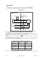
Appendix E
Control Schematic for Wiring of Intrinsically safe ICoT (WD-10836)
(Sheet of 2 of 4)
NONHAZARDOUS LOCATION
HAZARDOUS LOCATION
CLASS I, DIV 1, GROUPS A,B,C,D
CLASS II, DIV 1, GROUPS E,F,G
CLASS III, DIV 1
ROSEMOUNT 275 HART
COMMUNICATOR-NOTE 4
ICoT SERIES
POSITIONER
ASSOCIATED APPARATUS
(INTRINSIC SAFETY
BARRIERS) MTL MODEL
707 OR 787S
NOTE 1
MTL MODEL 7087 USED FOR
DIGITAL ON/OFF IN RTS
3
1
4
2
3
1
4
2
4
1
5
2
4
1
5
2
4-20mA
CONTROL
EQUIPMENT
NOTE 2
NOTE 3
ANALOG
OUTPUT
{
MAGNUM
SWITCH
OPTION
1. Associated apparatus manufacturer’s installation drawing must be followed when installing this equipment.
2. Control equipment connected to associated apparatus must not use or generate more than 250V.
3. To maintain intrinsic safety, each field wiring pair (4-20 mA and Analog Output) must be run in separate cables or
separate shields connected to intrinsically safe (Associated Apparatus) ground.
4. ROSEMOUNT® 275 HART® COMMUNICATOR is NOT FMRC approved for use in Class II and III Hazardous
Locations.
5. For Class II and III locations where rigid metal conduit is not used, seal ICoT cable entries against dust and fibers
using an appropriate NRTL listed cable gland fitting.
6. Installation should be in accordance with ANSI/ISA RP12.6 and the National Electrical Code (ANSI/NFPA 70).
MAXIMUM FIELD WIRING CAPACITANCE AND INDUCTANCE
HAZARDOUS LOCATION &
CONFIGURATION
MAXIMUM ALLOWABLE
FIELD WIRING
CAPACITANCE
MAXIMUM ALLOWABLE
FIELD WIRING
INDUCTANCE
GP A OR B LOCATION W/
COMMUNICATOR
30nF
4.0mH
GP C,D,E,F,G LOCATION
W/ COMMUNICATOR
230nF
16mH
GP A OR B LOCATION
W/OUT COMMUNICATOR*
100nF
4.0mH
GP C,D,E,F,G LOCATION
W/OUT COMMUNICATOR*
300nF
16mH
* ROSEMOUNT® 275 HART® COMMUNICATOR not used or used only on the INPUT side of associated apparatus.
10/31/02
Tech-304/DWO 14195
Page 35 of 39
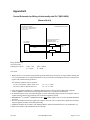
Appendix E
Control Schematic for Wiring of Intrinsically safe ICoT (WD-10836)
(Sheet of 3 of 4)
NONHAZARDOUS LOCATION
HAZARDOUS LOCATION
CLASS I, DIV 1, GROUPS A,B,C,D
CLASS II, DIV 1, GROUPS E,F,G
CLASS III, DIV 1
ROSEMOUNT 275 HART
COMMUNICATOR-NOTE 4
ICoT SERIES
POSITIONER
ASSOCIATED APPARATUS
(INTRINSIC SAFETY
BARRIERS) MTL MODEL 3045
NOTE 1
MTL MODEL 7087 FOR DIGITAL
ON/OFF INPUTS
3
1
4
2
3
1
4
2
4
1
5
2
4
1
5
2
4-20mA
CONTROL
EQUIPMENT
NOTE 2
NOTE 3
ANALOG
OUTPUT
{
MAGNUM
SWITCH
OPTION
1. Associated apparatus manufacturer’s installation drawing must be followed when installing this equipment.
2. Control equipment connected to associated apparatus must not use or generate more than 250V.
3. To maintain intrinsic safety, each field wiring pair (4-20 mA and Analog Output) must be run in separate cables or
separate shields connected to intrinsically safe (Associated Apparatus) ground.
4. ROSEMOUNT® 275 HART® COMMUNICATOR is NOT FMRC approved for use in Class II and III Hazardous
Locations.
5. For Class II and III locations where rigid metal conduit is not used, seal ICoT cable entries against dust and fibers
using an appropriate NRTL listed cable gland fitting.
6. Installation should be in accordance with ANSI/ISA RP12.6 and the National Electrical Code (ANSI/NFPA 70).
MAXIMUM FIELD WIRING CAPACITANCE AND INDUCTANCE
HAZARDOUS LOCATION &
CONFIGURATION
MAXIMUM ALLOWABLE
FIELD WIRING
CAPACITANCE
MAXIMUM ALLOWABLE
FIELD WIRING
INDUCTANCE
GP A OR B LOCATION W/
COMMUNICATOR
30nF
4.0mH
GP C,D,E,F,G LOCATION
W/ COMMUNICATOR
230nF
16mH
GP A OR B LOCATION
W/OUT COMMUNICATOR*
100nF
4.0mH
GP C,D,E,F,G LOCATION
W/OUT COMMUNICATOR*
300nF
16mH
* ROSEMOUNT® 275 HART® COMMUNICATOR not used or used only on the INPUT side of associated appara-
10/31/02
Tech-304/DWO 14195
Page 36 of 39
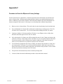
Appendix E
Control Schematic for Wiring of Intrinsically safe ICoT (WD-10836)
(Sheet of 4 of 4)
NONHAZARDOUS LOCATION
HAZARDOUS LOCATION
CLASS I, DIV 1, GROUPS A,B,C,D
CLASS II, DIV 1, GROUPS E,F,G
CLASS III, DIV 1
ASSOCIATED APPARATUS
(INTRINSIC SAFETY
BARRIERS) NOTES 1 & 2
ICoT SERIES
POSITIONER
4-20mA
CONTROL
EQUIPMENT
NOTE 4
NOTE 5
ANALOG
OUTPUT
Entity parameters for
each field wiring
terminal pair of ICoT:
Vmax = 30V
Ci = 120 pF
Imax = 100mA
Li = OmH
CSA Notes:
1. Barrier must be a CSA certified, single channel grounded shunt-diode zener barrier or single channel isolating barrier or one dual channel or two single channel barriers may be used where both channels have been certified for use
together with combined entity parameters.
The following conditions must be satisfied:
Voc or Vo less than or equal to Vmax or Ui
Isc or Io less than or equal to Imax or Ii
Ca > Ci + C Cable
La > Li + L Cable
2. Associated apparatus manufacturer’s installation drawing must be followed when installing this equipment.
3. Control equipment connected to associated apparatus must not use or generate more than 250V.
4. To maintain intrinsic safety, each field wiring pair (4-20 mA and Analog Output) must be run in separate cables or
separate shields connected to intrinsically safe (Associated Apparatus) ground.
5. ROSEMOUNT® 275 HART® COMMUNICATOR is NOT FMRC approved for use in Class II and III Hazardous
Locations.
6. For Class II and III locations where rigid metal conduit is not used, seal ICoT cable entries against dust and fibers
using an appropriate NRTL listed cable gland fitting.
7. Installation should be in accordance with ANSI/ISA RP12.6 and the National Electrical Code (ANSI/NFPA 70).
8. Install in accordance with Canadian Electrical Code Part 1.
10/31/02
Tech-304/DWO 14195
Page 37 of 39
Appendix F
Procedure to Reset the EEprom to Factory Settings
The ICoT Positioner is a digital device. Positioner operation relies on data that is stored in the positioner’s EEprom chip. Calibration and configuration data that has been established during the positioner’s calibration is stored in the EEprom. Under abnormal conditions this stored information can
become corrupted. If this occurs it is necessary to reset the chip and re-calibrate the positioner.
1.)
Remove power to the positioner. This can be done by removing the plug-in style terminal strip.
2.)
Press and hold the CAL button while replacing the terminal strip (returning power). The LCD
will show ICoT Positioner-Rev ” for several seconds while holding down the CAL button.
3.)
Continue to hold the CAL button until the LCD shows “reset EEprom values to Mfg values.
When this statement appears release the CAL button.
4.)
After releasing the CAL button you will be prompted to enter 4.0 mA. Change your input to the
positioner to exactly 4.0 mA and press the CAL button. If your zero position signal is other than
exactly 4.0 mA then use the Up/Down arrow buttons to adjust the value shown on the positioner’s LCD to match the zero position mA and press the CAL button.
5.)
You will then be prompted to enter 20 mA. Change your input to the positioner to exactly 20.0
mA and press the CAL button. If your full-scale position signal is other then exactly 20.0 mA
then use the Up/Down arrow buttons to adjust the value shown on the positioner’s LCD to match
the full-scale position mA and press the CAL button.
6.)
The positioner will automatically return to normal operating mode.
7.)
If desired, follow the normal calibration procedure as described in the manual.
10/31/02
Tech-304/DWO 14195
Page 38 of 39
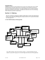
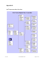
Appendix G
Hart® Communicator Menu Flow Chart
10/31/02
Tech-304/DWO 14195
Page 39 of 39