1
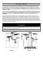
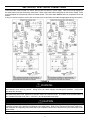
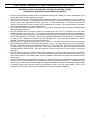
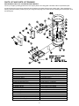
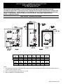
INDUCED DRAFT COMMERCIAL WATER HEATERS
SUPPLEMENT INSTRUCTIONS
TO PART #238-47675-00
THIS INSTRUCTION SUPPLEMENT IS ONLY INTENDED TO GIVE INSTALLATION INSTRUCTIONS AND
INFORMATION RELATED TO THE INDUCED DRAFT WATER HEATERS WHERE THESE MODELS DIFFER FROM
THE ATMOSPHERICALLY VENTED MODELS IN THE GENERAL INSTALLATION INSTRUCTIONS (238-47675-00).
REFER TO THE GENERAL INSTRUCTIONS (238-47675-00) FOR ALL APPLICABLE WARNINGS AND
INSTALLATION PROCEDURES.
SECTION II: SPECIFICATIONS
Capacity
(gal.)
65
80
Input
(BTU/Hr)
625,000
725,000
AMP
Draw
3.00
3.00
A
(in.)
69 3/8
79 5/8
B
(in.)
54 1/8
64 1/4
C
(in.)
41 7/8
55 1/8
D
(in.)
68 7/8
79 1/8
Vent
Dia (in.)
8
8
Capacity
(Liters)
246
303
Input
(kW/Hr)
183.0
212.5
AMP
Draw
3.00
3.00
A
(cm)
176
202
B
(cm)
137.5
163
C
(cm)
106
135
D
(cm)
175
201
Vent
Dia (cm)
20.3
20.3
Notes:
1. All models use an induced draft blower with integral damper and intermittent pilot ignition requiring a power source of
(120volt, 60Hz or 220 volt, 50 Hz).
2. Suffix “N” denotes natural gas, Suffix “X” L.P. gas.
3. May be installed on combustible flooring.
238-47703-00A Rev 1/09
SECTION V: VENTING
The water heater models described above in this supplement are of the induced draft type which rely on an
induced draft blower to pull the combustion products through the flue tubes of the water heater. An integral
gravity damper on the induced draft blower outlet is forced open by the air pressure from the blower and closes
at the end of each burner cycle. NO ADDITIONAL VENT DAMPERS ARE TO BE ATTACHED TO THE OUTLET OF
THESE APPLIANCES.
These water heaters have been approved for vertical venting through a lined masonry chimney or double wall
vent pipe. DO NOT VENT THESE WATER HEATERS HORIZONTALLY WITH THE VENT TERMINATING THROUGH
THE WALL TO THE OUTSIDE. ALL VENTING MUST TERMINATE THROUGH THE ROOF WITH A VERTICAL
DISCHARGE.
The vent connector attached to the vent collar on the blower must be 8" (20 cm) in diameter. The venting size was
designed to produce a negative pressure inside the venting system when properly installed. Horizontal piping must be
sloped upward at least 1/4" inch per linear foot (2.1 cm/m) of length. All vent piping must be well supported to avoid
sagging or adding excessive weight onto the blower assembly. This water heater may be commonly vented with another
gas appliance, providing the commonly shared vent is the proper size to handle exhaust gases from both appliances. For
proper venting, limit the number of elbows in the venting system. All connections in the venting system must be securely
fastened with sheet metal screws or other approved methods. Consult local codes and ordinances. See Figures 2 & 3 on
the below for common venting connections.
WARNING
This water heater must not have another gas appliance vented into the vent connector. Consult the venting
tables in the latest edition of the National Fuel Gas Code ANSI Z223.1 or in Canada CAN1-B149.1 or B149.2 and/or
local code officials for proper application for your area.
Failure to install a proper venting system can result in fire, injury, or death.
Figure 2
Figure 3
2
SECTION VIII: ELECTRICAL CONNECTIONS
This water heater must be wired to a 120volt, 60Hz or 240 volt, 50/60 Hz. power supply. Refer to the wiring diagram on
the water heater for proper field wiring connections. Refer to the water heater rating plate for the correct voltage. Refer
to the nameplate for the total amp draw for this water heater. The water heater must be wired on a separate circuit and
breaker.
If wiring in conduit is required, cut the line cord close to the control board and make the appropriate wiring connections.
FIGURE 4
WARNING
Turn off or disconnect the electrical power supply to the water heater before servicing. Label all wires prior to
disconnection when servicing controls. Wiring errors can cause improper and dangerous operation. Verify proper
operation after servicing.
All electrical wiring must be installed and grounded in accordance with local codes, or in the absence of local codes,
the National Electrical Code, ANSI/NFPA 70 and/or CSA C22.2 Electrical Code. In Canada, follow the latest edition of
the Canadian Electrical Code (Part 1, CSA-C22.1) and all applicable local codes.
CAUTION
This water heater must be wired on a separate circuit. Failure to wire on a separate circuit may cause improper
operation or failure of the electrical components of the water heater. Refer to the “Electrical Connections” section of
the Installation and Operating Instructions Manual for complete instructions on electrical wiring and connections to the
water heater.
Do not energize the electric circuit before the water heater tank is filled with water.
3
SECTION X: MAINTENANCE
The following maintenance should be performed by a qualified service technician at the minimum periodic interval listed
below.
1. Bi-annually, oil the induced draft motor in the ports of the front and rear motor bearings with 4 drops each of SAE 20
motor oil.
2. Annually, inspect the blower wheel for debris and clean as necessary.
3. Inspect the venting system for corrosion and leaks. Replace any defective sections of vent pipe.
4. Inspect the blower vent damper for proper movement, making sure the damper extends to the full open position after
the blower reaches full speed (see Figure 5). If the damper blade does not fully open, remove the vent connector and
make sure the blower wheel is clean and debris has not fallen on the damper blade or blower wheel. If the damper
binds, replace the blower assembly. DO NOT ATTEMPT TO REPAIR THE DAMPER!
Figure 5
4
SECTION XI: DIAGNOSTIC AND TROUBLESHOOTING GUIDE
DIAGNOSTIC GUIDE FOR HONEYWELL INTEGRATED CONTROL SYSTEM
SEQUENCE OF OPERATION FOR INDUCED DRAFT MODELS
1. When the tank temperature drops below the temperature setpoint on the display, the control sends power to the
induced draft blower to start the ignition sequence.
2. When the blower reaches the full operating speed, the pressure switch closes, completing the 24 volt circuit to the
safety circuit of the control. If the exhaust vent becomes blocked or the blower fails, the pressure switch will
open, the gas valves close, and the blower stops after a 5 second post-purge. The blower will restart and
continue to operate in the lockout condition until the blockage is removed or the venting problem is corrected.
Error code 29 will appear on the water heater display.
3. The control will continue to operate the blower for 15 seconds to “prepurge” any flue products remaining before
starting the ignition sequence.
4. After the prepurge period, the control sends 24 volt power to the pilot valve “PV” terminals on the gas valve
allowing pilot gas to flow to the pilot. The control also sends high voltage through the pilot electrode to spark to
the pilot hood and ignite the pilot gas. If the pilot does not ignite within 90 seconds, the pilot valve is denergized
and the sparking stops for 75 seconds. The control will attempt to ignite the pilot two more times. If the pilot does
not light on the 3rd attempt, the control will go into “soft lockout” for 1 hour and then will repeat the 3 ignition
attempts. The blower is off during the “soft lockout” period.
5. When the pilot is lit, the flame is sensed by the flame sense rod. The flame sense signal received by the control
board causes the sparking to stop and the main gas valve to open. The main burners ignite from the pilot flame.
The pilot is continually monitored by the flame sensing circuit. If for any reason, the pilot flame is not sensed by
the flame sensing circuit, the gas valves close. After a 75 second delay, the pilot valve opens and the pilot
electrode sparks to relight the pilot. The same sequence will occur in the event of a power supply or gas supply
interruption.
6. The main burners continue to operate until the water temperature in the tank increases past the control setpoint,
which will cause the gas valve to close. The blower stops operating 5 seconds after the gas valve closes. The
water heater remains in the standby mode until the temperature drops below the setpoint and initiates another
heating cycle.
7. If for some reason, the tank temperature should reach or exceed 200˚F, then the control closes the gas valve and
goes into a “hard lockout” state and will not operate until reset by a qualified service person. The display will read
“error code 65”, which indicates the tank high limit temperature has been exceeded. No attempt should be made
to reset the control until a service person has corrected the cause of the high limit condition. Refer to the
diagnostic service section at the end of this Installation and Operating Instructions Manual.
5
DIAGNOSTIC ERROR CODES AND TROUBLESHOOTING PROCEDURES FOR HONEYWELL INTEGRATED
CONTROLS (INDUCED DRAFT MODEL SERIES)
Error
Code
Definition of Code
4
Low Flame Sense
Current
2
Pressure Switch Failed to
Open (Stuck Closed)
29
Pressure Switch Failed to
Close
6
Flame Sensed Out of
Normal Sequence
(Before Opening Gas
Valve or After Closing
Gas Valve)
23
Flame Detected Before
Ignition
24
Flame Detected After
Heating Cycle Completes
31
32
Upper Sensor Readings
Faulty
Lower Sensor Readings
Faulty
Cause of Problem and Actions Taken to Correct
Determine flame sense current in the Service Mode with the water heater
operating. If less than 1.0 microamps, check pilot flame sense rod and wire.
Clean flame sense rod with emery cloth. If problem is not solved, replace pilot.
The pressure switch contacts did not return back to the normally open position at
the end of the last heating cycle. The control checks to make sure the pressure
switch is in the normally open position before allowing the blower to start the
ignition sequence. Check to make sure the pressure switch tubing is not blocked.
If the pressure switch tubing is clear, replace the pressure switch.
The pressure switch contacts did not close after the blower was energized.
Check to make sure the blower is energized at the beginning of the heating cycle.
If the blower did not start, check to make sure there is power to the motor.
Replace blower or control board if defective. Check to make sure the venting
system is not blocked. Make sure the vent length does not exceed the specified
limits. Make sure the vent terminal is not blocked. Check to make sure the
pressure switch tubing is clear. Replace the pressure switch if the venting system
has checked out O.K. Control will reset once problem is corrected.
Check to make sure gas valve has closed. No voltage should be present at the
gas valve before or after ignition cycle. Make sure wire positions on the wire
harness are correct. If gas valve is stuck open, replace.
Check to make sure gas valve has closed. No voltage should be present at the
gas valve before the ignition cycle. Make sure wire positions on the wire harness
are correct. If gas valve is stuck open, replace.
Check to make sure gas valve has closed. No voltage should be present at the
gas valve before the ignition cycle. Make sure wire positions on the wire harness
are correct. If gas valve is stuck open, replace.
Resistance of upper sensor out of operating range. Check continuity of wire
harness to upper sensor, and if O.K., replace upper sensor.
Resistance of lower sensor out of operating range. Check continuity of wire
harness to lower sensor, and if O.K., replace lower sensor.
Pilot flame sensor rod is shorted to ground. Check to see if flame sensor wire
has bare spots touching metal parts of if flame sensor rod is touching the pilot
shield or other metal parts. Replace pilot if flame sense wire is damaged or flame
rod is bent. Make sure pilot shield is not touching the pilot flame sensor.
57
Flame Rod Shorted to
Ground
58
AC Line Frequency Error
– Signal Too Noisy or
Frequency Incorrect
Check line voltage frequency to the water heater. Determine if there are wide
fluctuations. Call an electrician if the problem persists. The water heater should
be on a separate line.
59
Line Voltage Too Low or
High
61
DC Output Voltage
Unstable
62
Maximum Number of
Retries Detected
Check line voltage to the water heater. Determine cause of low or high voltage.
Call an electrician or your utility. The water heater should be on a separate line.
Check line voltage to the water heater for erratic readings. Also check wiring to
make sure there are no shorts. If power supply and wiring are O.K., replace
control board.
Pilot is either not lighting or not staying lit during ignition cycle. Check inlet gas
pressure for minimum pressure on rating label. Is pilot electrode sparking?
Check gas valve wire harness for broken wires or shorts. If 24 volts is present
between PV and PV/MV terminals at the gas valve, replace gas valve. Check for
voltage output to the yellow and red gas valve wires on the control board pins. If
during the ignition trial period, there is no voltage present at the control board pin
terminal for the red and yellow wires leading to the gas valve, then replace the
control board. Replace pilot if wires are damaged or electrode is damaged.
6
Error
Code
Definition of Code
63
Maximum Number of
Ignition Recycles
Detected
64
Electronics Failure
65
High Water Temperature
(Over 200˚F)
Cause of Problem and Actions Taken to Correct
Pilot flame is lost during run cycle, then restablished on ignition cycle. Check inlet
gas pressure. Is gas pressure dropping below the minimum operating pressure
on the rating label after the main gas valve opens? Is the gas pipe size to the
water heater adequate? Check the pilot shield position and condition of the
burners. Clean or replace as needed. Check the pilot flame and observe the
microamp output on the run cycle. Check the pilot tubing to the pilot and replace
if crimped or damaged. Replace pilot if wires, flame sensor, or electrode is
damaged.
Replace control board.
Water temperature in tank has exceeded 200˚F. Check lower sensor. Make sure
sensor is fully inserted into the well (clip on sensor wire secures sensor in place).
Check lower and upper (where used) sensor readings. If not within
specifications, replace sensor. If sensor and wire harnesses check O.K., replace
control board.
7
PARTS LIST AND PARTS LIST DRAWING
REPLACEMENT PARTS LIST FOR INDUCED DRAFT MODELS
Contact your supplier, plumbing professional or the company listed on the rating plate of the water heater for replacement parts.
Provide the part name as well as the model and serial number(s) of the water heater(s) when ordering parts. When applicable, the
following information shall be provided: type of gas, voltage and amperage, item number (from the following list) and description (from
the following list)
PART NAME AND DESCRIPTION
1. Induced Draft Blower/Motor Assembly
19. Control Box
2. Blower Mounting Flange
20. Control Box Cover
3. Blower Mounting Flange Gasket
21. Transformer
4. Collector to Blower Transition Duct
22. Temperature display (Emergency shut-off)
5. Blower-Vent Pipe Adapter
23. On/Off Switch
6. Air Pressure Switch
24. Integrated Control
7. Pressure Switch Tubing
25. Sensor Well
8. Flue Baffle
26. Wire Harness - Thermostat to Blower
9. Clean-out Hole Tank Cover
27. Wire Harness - Control Box
9a. Clean-out Hole Cover O-Ring (not shown)
28. Outer Cleanout Cover
9b. Clean-out Hole Cover Gasket (not shown)
29. Flue Collector Cover
10. Radiation Shield
30. Flue Collector Cover Gasket
11. Main Burner(s)
31. Anode Rod (Not Shown)
12. Burner Tray
32. Tank Leg Thermal Break
13. Pilot Burner Assembly
33. Manual shut-off (optional)
14. Pilot Supply Tube
34. T&P Relief Valve
15. Pilot Draft Shield
35. Drain Valve
16. Main Burner Manifold
36. Lower Sensor
17. Gas Valve (Emergency Shut-off Device)
37. Upper Sensor
18. Main Burner Orifice(s)
8