1
Manual
Version 2.00
April 3, 2012
PowerFLARM Device Manual for FW v2.00
1
Contents
Introduction ................................................................. 3
Installation ................................................................... 5
General Advice on Installation........................................................... 5
Housing ....................................................................................................... 6
Connections ............................................................................................... 8
GPS-System ............................................................................................. 11
FLARM-Device Communication ..................................................... 12
Transponder and ADS-B 1090ES Reception ............................. 13
Audio ......................................................................................................... 13
Micro SD-Card........................................................................................ 14
Power Supply ......................................................................................... 14
Technical Data ....................................................................................... 17
Operation ................................................................... 18
General Advice on Operation .......................................................... 18
Start-Up .................................................................................................... 21
Fault Reporting and other Information ...................................... 21
Operation ................................................................................................. 22
Normal Operation ................................................................................ 22
Operation with Mode S/C transponder ...................................... 24
Collision Warnings............................................................................... 25
Settings Menu ........................................................................................ 27
Essential Settings Prior to First Flight ......................................... 29
Legal Notes ................................................................. 30
Product Warranty ................................................................................ 30
Limitations .............................................................................................. 30
Legal Liability ........................................................................................ 31
Conformity Declaration ..................................................................... 32
RF Radiation Hazard Warning ........................................................ 33
Maximum Antenna Gain .................................................................... 33
Industry Canada Notice and Marking .......................................... 33
April 3, 2012
2
Introduction
A PowerFLARM™ device draws its position and movement
information from an internal GPS-receiver. The position measured
is rendered more accurate by an integral pressure sensor. The
device calculates the predicted flight path and transmits this
information as a short, low-power digital signal burst at onesecond intervals together with a unique identification code. At the
same time, the device receives similar signals from PowerFLARM
devices installed in other aircraft and within radio range, or from
aircraft equipped with ADS-B-OUT (1090ES), Mode-C and Mode-S
transponders (if interrogated by ground radar or TCAS). The
device compares the signals received with its own projected flight
path. An optional, additional feature will be for the device to
compare its own projected flight path with the positions of known
fixed obstacles (e.g. cables, aerials, cable railways, avalanche
detonation sites) held in the device's data base.
If the device determines one or more threats of a dangerous
conflict with another aircraft or obstacle, it warns the user of the
most dangerous threat as per the internal calculation. Acoustic
warnings are issued via a warning bleeper and headset audio
output, also an optical warning via an LCD display. These signals
indicate the height of the threat, the direction from which it has
been detected, and the altitude difference. For gliders, during
thermalling, a different calculation algorithm is applied from that
used in straight flight. The GPS- and collision threat data received
are also fed to a serial data port output for use by other devices
such as an external display and PDA. Compatible equipment is
available from a number of suppliers.
Warnings are issued in accordance with the time remaining to a
possible collision, not the geometric distance between the aircraft.
The first warning is typically issued between 19 and 25 seconds
prior to the calculated possible collision with aircraft or obstacle;
the second is issued 14 to 18 seconds beforehand, and the third 6
to 8 seconds in advance. Warnings are sustained as long as the
threat remains relevant. Depending upon updated data and
prediction, the threat may be downgraded or deleted. Warnings
are selective, i.e. they are only issued if the algorithms detect a
PowerFLARM Device Manual for FW v2.00
3
high probability of a dangerous convergence in the immediate
future.
Communications between PowerFLARM / FLARM devices employ
a proprietary, copyright protected protocol in different frequency
bands allocated by region. Effective range depends upon the
position in which device and antenna is fitted.
The communications system between devices is protected against
unauthorised access. The design is patent protected. There is no
public access to the protocol. Any unlicensed use, copying,
distribution, conversion, replication, de-compiling, reverse
engineering, or further transmission of knowledge so acquired
relating to the system components or software, in whole or in
part, is forbidden and will result in legal enforcement action.
Technical data may be changed at any time and without prior
warning. Some named functions are not provided in all versions of
the device, but may be provided at extra cost or for a recurring
fee.
April 3, 2012
4
Installation
General Advice on Installation
Installation and operation is on a non-interference and nonhazard basis, and may not be allowed to endanger the safe
operation of certificated equipment that is either necessary or
required by regulation for safe flight. Installation must comply
with official requirements.
The device must be so secured that the pilot can see the displays,
hear the acoustic warnings, and operate the turning-button. The
device must not obstruct the pilot in his operation of the aircraft
(including emergencies); in particular at all times it must not
obstruct his view of the sky, even in the event of serious vibration
or acceleration. The device is not suitable for use in conjunction
with night vision equipment, for night flying, or in pressurised
cabins.
Ideally, the device will be fitted to the instrument panel glareshield or cockpit sidewall. If the device internal display is in use,
the rear face of the device with cable connectors must face the
direction of flight. If the device is coupled to an external display
with controls, it can be installed in another position or point in a
different direction. Usually, this will require the use of separate
communications and GPS aerials.
No antenna may be in contact with any object which might be the
source of electrostatic discharge.
Stub and whip antennas must not touch any object, e.g. the cockpit
windscreen.
The device will not operate properly in the absence of an antenna
or if the antenna is not properly screwed tight; the device cannot
self-test for correct antenna function.
For updates, configuration and flight data evaluation it is helpful if
the device is installed such that the data connectors and the
PowerFLARM Device Manual for FW v2.00
5
microSD-reader are easily accessible or reachable with an
extension cable. The serial number must be known for software
updates.
It is advisable that the device is so fitted to the aircraft that the
turn-button cannot be inadvertently pressed during entry to or
egress from the aircraft. Should the device or any associated
components be fitted to a part of the aircraft that will be
jettisoned in an emergency, suitable break points should be
incorporated to prevent any interference with the jettison
sequence.
Cables must not be folded or placed under tension. Adequate
space must be left for the cable connectors. Cables for data and
external devices must be shortened as necessary: to prevent the
occurrence of inductive effects they may not be coiled. Only a
single device may be installed in each aircraft.
The device and any associated aerials should be located as far
away as possible -- at least 30 cm (1 ft) -- away from any other
GPS aerial and the magnetic compass.
After installation, an inspection must be made to ensure that the
device does not interfere with any mechanical, electrical,
electronic (radio) or magnetic (e.g. compass) system, and this fact
must be recorded in the aircraft documents. In addition, the
aircraft documents must bear a record of serial number and
Software Version Number. If employed in a fixed installation, the
Means of Compliance must be recorded in the aircraft
documentation, and an AFM Supplement is to be carried on board
the aircraft. The user must ensure that installation and operation
complies with all applicable law in the usage location’s
jurisdiction.
In case of questions or problems, please contact your dealer
directly.
Housing
The lower face of the polycarbonate housing has two threaded
screw holes, so that the device may be easily secured using two
April 3, 2012
6
metric M4 screws (max. 10 mm long). The device must be fitted to
a flat surface and the housing not subjected to any mechanical
stress. Several types of adapter fixtures are available.
The housing can also be secured using 3M DualLock industrial
fasteners, which can be secured and released several times. Users
should note that the adhesive used on 3M DualLock is
exceptionally strong and may not easily release. The adhesive tape
should not cover the battery compartment lid, but should be
applied elsewhere on the housing.
The housing is not air or watertight and users should avoid the
ingress of solid particles and liquids. Should the device get moist,
it must be completely dried prior to further use. If the device
becomes wet, it may be permanently damaged and rendered
unusable; no guarantee claim will be accepted for any device
damaged by moisture. Should the device be suddenly cooled this
may result in the formation of internal condensation. The housing
may only be cleaned using a slightly moist non-abrasive cloth
without a chemical cleaning agent. The housing does not resist
scratches or abrasion.
The plastic housing is black to reduce glare and has been tested in
the temperature range -10 °C to +60°C. Care should be taken to
avoid over-heating due to direct or indirect sunshine, in particular
because the housing can become deformed at temperatures above
+84 °C without any mechanical tension, and with mechanical
tensions also at lower temperatures. The device must not be
locally over-heated by exposure to focused sunrays, and care is
required when cockpit doors or canopies have been opened (risk
of fire to due lens effect). High temperatures significantly reduce
battery runtime when rechargeable batteries are used.
PowerFLARM Device Manual for FW v2.00
7
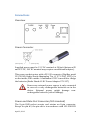
Connections
Overview
Power Connector
Supplied power must be 12 V DC nominal at 500mA (between 8V
and 27V DC, 24V DC nominal may require an additional adapter).
This power socket mates with a PP-012 connector (DigiKey part#
CP-012-ND, Radio Shack Adaptaplug Tip „A“ 273-334). VDC(+) is
on the inside, GND outside. A minimum of 12V is needed to charge
the batteries (Radio Shack AC-DC Power Adapter 273-357)
Ensure any external power source is only connected
in case no or only rechargeable batteries are in the
device. External power might damage nonrechargeable batteries (risk of leakage).
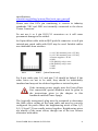
Power and Data Port Connector (IGC standard)
The 8-pin RJ45-socket accepts and retains an 8-pin connector.
Except for pin #3, the pin-out is in accordance with IGC GNSS FR
April 3, 2012
8
specifications
www.fai.org/gliding/system/files/tech_spec_gnss.pdf
Please note that IGS’s pin numbering is reverse to industry
standards. VDC and GND are internally connected to the above
‘Power Connector’
Do not use 6 or 4 pin RJ-12/11 connectors as it will cause
permanent damage to the socket.
An 8-pin ribbon cable with an RJ45 push-fit connector or an 8-pin
twisted-pair patch cable with RJ45 may be used. Suitable cables
are obtainable from retailers.
1: +12 V DC nominal (+8 to +27V DC)
2: +12 V DC nominal (+8 to +27V DC)
3: Device supplies + 3V DC
4: GND
5: TX (RS232): only 1 user!
6: RX (RS232): only 1 user!
7: GND
8: GND
Pin 1
Pin 8
(view from rear)
For 8-pin cables pins 1=2 and pins 7=8 should be linked. If the
other wires are not to be used, they should be individually
insulated and may not be soldered together or twisted in pairs.
If the incoming power supply uses the Power/Data
Port connection, special attention must be given to
the instructions given in the chapter in this
handbook entitled Power Supply.
The (typically transparent) plug must be examined to determine
the cable colour coding so the open cable end may be correctly
configured. On patch cables the neighbouring wires of Pins 1/2,
3/4, 5/6 and 7/8 are usually twisted together. Neighbouring wires
are usually of the same colour, though one of the two colours
alternates with white.
PowerFLARM Device Manual for FW v2.00
9
On the Data Port connector, PowerFLARM can transmit a
combination of GPS, traffic and alarm information to various types
of devices (e.g., external displays, flight computers, loggers etc.)
The type of data output and the connection parameters (Baud
rate) can be configured from the Menu or by commands on the
Data Port itself.
As of Firmware version 2.00, PowerFLARM implements versions
3, 5 and 6 of the Data Port specification with GPS/FLARM
proprietary NMEA and Garmin TIS data. The connected device
can select the protocol version it requires.
Please refer to the Data Port Specification available from
http://www.flarm.com/support/manual/ for details.
If you connect a device to the Data Port, make sure
that the installation conforms to the requirements
set forth in the Data Port Specification.
Do not connect more than one device at the same
time.
Audio
The audio signal is a standard de-coupled aviation signal of no
more than 1 V. The connector is a standard 3.5 mm jack plug.
Communications Antennas
The
primary
communications
antenna
for
the
FLARM/PowerFLARM device communication must be connected
to the socket labelled ‘FLARM A’. For proper operation the
included ADS-B antenna (blue label) must be carefully and tightly
screwed to the rpSMA socket labelled ‘ADS-B’.
Make sure the FLARM antenna and the ADS-B antenna
(blue band) are not accidentally swapped!
April 3, 2012
10
The installation has a great influence upon both transmission and
the reception range achieved, and thus requires careful
consideration. The antennas must be vertical to ensure
unimpeded emission especially to the front, and to the sides. Users
are advised not to install the device within or under the
instrument panel without external antennas. Horizontal or nonupright antenna presentation is unacceptable. No electrically
conducting surfaces (e.g. metal, carbon fibre) should be located
over or immediately alongside the antennas. The antennas must
not be subjected to physical pressure and may not be bent. Ensure
the antenna does not touch the cockpit windscreen.
If a second flat FLARM/PowerFLARM device
communications antenna with the extension cable
(used for reception of FLARM/PowerFLARM device
signals only, included in shipments to the USA) is
used, it should be connected to socket labelled
‘FLARM B’; ensure it is located at least 0.6 meters (2
ft) from the device.
Alternative offset antennas, external antennas and antenna
extension cables (50Ω on normal SMA) can be obtained from
retailers. The installation must be within a Zone 2A or 3 as defined
by DO-160/F Section 23.
GPS-System
The GPS system in the device is subject to the limitations found in
typical GPS applications. It is not aviation certified.
The device will not work without adequate GPS
reception.
The device can be operated using both the GPS antenna within the
housing and with an external GPS antenna (not supplied)
connected to the MCX socket. Connecting an external antenna
automatically deactivates the internal antenna.
PowerFLARM Device Manual for FW v2.00
11
Operation with an internal GPS Antenna
When operating with the internal GPS antenna, the device
presentation must be unhindered to the sky ahead and sides.
Further, the upper side of the device must not be covered.
Operation with an external GPS Antenna
The antenna should be located in an upright position such that it
has an unhindered presentation to the sky, including when the
aircraft is in a turn. There should be no electrically conducting
surfaces (e.g. metal, carbon fibre) over or immediately alongside
the antenna. Ideally, the antenna will sit atop the instrument panel
coaming. Conducting surfaces under the antenna may have a
positive effect upon antenna function. If more than one GPS
antenna is present, it is recommended that they are at least 25 cm
(1 ft) apart; the same holds good for separation from the
PowerFLARM device communications antenna.
FLARM-Device Communication
The FLARM/PowerFLARM device radio communication is made
using a license free frequency band known as ISM/SRD band. This
means that the band is also used by other applications all of which
must meet the same restrictions in transmission power, duty
cycle, etc.). The device has no exclusive rights to use this
frequency band, so there is no guarantee that reception will be
free from interference by other users. Nevertheless, due to the low
power nature of the devices in the frequency band and a
sophisticated use of the transmission channel, interference is
unlikely.
The use of unlicensed bands by aircraft is subject to a number of
limitations, with some national differences. The pilot and user of
the device are solely responsible for ensuring that the device is
used in accordance with the current local regulations.
Essentially, the FLARM/PowerFLARM device communications
protocol places no limit on the number of devices that may be
contacted within the working range. However, a high number of
devices within range leads to a reduction in the probability
('graceful degradation'), that a single signal report can be
April 3, 2012
12
received. But the probability that the next signal from the same
transmitter will not be received is generally small. The device is
designed to simultaneously receive and process the signals from
more than 50 aircraft within radio range. A large number of
signals from other aircraft does not reduce the working range.
Transponder and ADS-B 1090ES Reception
The ADS-B / transponder antennas (marked with blue band) are
inserted and screwed to the reverse-polarity rpSMA socket as
marked. Make sure you do not mistakenly insert the
FLARM/PowerFLARM device communications antenna in this
rpSMA socket, and never use force.
Audio
To make sure that an acoustic warning can be heard above loud
ambient noise, the signal may be fed the Pilot’s headset. To this
end, there is a 3.5 mm socket for a jack plug on the rear side of the
device.
The preferred way of installation is to connect the jack to an AUX
or similar input of an Intercom or Audio Panel. Upon installation,
make sure that your audio equipment correctly mixes the
PowerFLARM audio signal with other audio sources in the cockpit
(Radio, NAV, other headset microphones). Make sure that Audio
Out is set to ‘ON’ in the menu. PowerFLARM will beep on the
buzzer and audio out on volume adjustment.
Depending on the audio equipment/headset, the
audio out signal may be very loud could and damage
a human ear. Upon installation, carefully adjust the
volume to a comfortable level.
The device also has an integrated warning beeper. The housing
front face has an outlet to improve sound release from the internal
bleeper. This outlet must not be obstructed by any adhesive agent.
When set at high volume, the bleeper sound level
could damage a human ear at close distance. The
volume is adjustable.
PowerFLARM Device Manual for FW v2.00
13
Micro SD-Card
The device has a built-in microSD card reader, also compatible
with microSDHC. The microSD card (also known as TransFlash) is
not supplied, but is in widespread use for mobile telephones and
can be purchased from most camera or mobile phone retailers.
The device uses the microSD card to update the firmware,
obstacle and terrain data, to configure the device and download
the flight logs.
microSD cards are smaller than SD cards or miniSD cards.
However, for communication with a PC there are mechanical
adapters for insertion of a microSD card in SD or a miniSD card.
Such adapters are often sold together with the cards.
Note, that the microSD card must be formatted to FAT or FAT32. If
your card is not yet preformatted to one of these two formats, do
so with your PC; the device does not format cards.
Insertion and Removal
Hold the card with the metal contacts on the right and insert
carefully into the slot; then, gently press with the fingertip until
the card is retained with a slight 'click'. To remove the card, press
the card gently into the device’s SD-reader slot until a slight click
releases the card, which can then be gently withdrawn. Do not use
force.
Power Supply
The device can be operated using the aircraft's own electrical
power system, disposable or rechargeable batteries.
Power Supply using the Aircraft's own Electrical Power
System
If the device draws its electrical power through the Power/Data
socket, there must be a direct galvanic link between the device
and aircraft battery via a 500 mA circuit breaker. This power
supply must be separate from any other instruments that are
essential for the safe conduct of the flight. In flight the pilot must
be able to isolate the device from the aircraft's electrical power
system without interrupting the power supply to any other
April 3, 2012
14
important systems. Possible reasons might be a suspected fault in
other on-board systems, the presence of smoke, the smell of
smoke, or flying over a country where the operation of the device
is not approved.
In spite of the integral electrical polarity guard, it is important not
to confuse the power supply with the data cable.
Ensure no non-rechargeable batteries are inserted in the unit.
Power Supply Using Batteries or Rechargeable Batteries
The device can be operated using different types of batteries or
rechargeable batteries. The device requires six AA cells or
compatible products:
-
Nickel Metal hydride (NiMh) rechargeable batteries
exceptionally
also
Alkaline
batteries
(Alkaline Manganese Cells)
The device should not be operated in conjunction
with any other types of battery; other types may
damage the device.
The battery type must be set under the settings menu. Never use
disposable batteries when the battery type is set to
“rechargeable”.
Battery endurance depends upon the type of battery,
the temperature, the incidence of traffic and display
brightness.
The battery life remaining is indicated above the
battery symbol on the right upper corner of the
traffic display.
PowerFLARM Device Manual for FW v2.00
15
Battery Insertion
The device has a battery compartment on the lower face, and
holds six AA batteries. The batteries are inserted by removing the
compartment lid. It is essential to ensure that the batteries are
inserted with the correct polarity, with no excessive application of
force on the battery compartment lid.
Rechargeable internal Batteries
The device features an internal NiMH battery charger. When the
device is turned off and electrically connected to the vehicle or
aircraft battery (either via “Power” socket or power pins on the
RJ45 socket), inserted batteries will be charged if the ambient
temperature lies within the allowed range for charging NiMH
batteries.
If non-rechargeable batteries are fitted to the device,
never connect your device to an external power
source (e.g. aircraft or vehicle battery)!
The internal batteries may only be charged if the device is resting
on a non-flammable, dry base. When the device is being
recharged, never allow it to remain unsupervised.
The integrated charging circuit will only charge
batteries at an ambient temperature of up to about
40 °C (104 °F). If possible, charge your batteries in a
cool, dry environment.
April 3, 2012
16
Technical Data
Dimensions:
Length: 94mm
Width: 96mm
Height: 46mm
User Interface:
Integral turn/push button
2” transflective LCD display
Audio:
Built-in warning beeper
Output for Headset Audio
Volume control
Communication:
Internal RS232 NMEA
Data output for Moving-Map
units and external displays
(only one user at a time!)
internal 3V power supply for
remote displays
Sensors and GPS:
Pressure sensor
Microphone
50-channel GPS receiver with
internal or external antenna
FLARM device communication:
Dual 868-930MHz FLARM
device Transceiver
ADS-B-IN/XPDR:
1090 MHz receiver for XPDR
Mode-C/S and ADS-B 1090ES
signals
Antennas:
868-930MHz FLARM device
antenna (Port ‘A’ rpSMA
socket)
868-930MHz extended FLARM
device antenna (Port’B’ SMA
socket)
ADS-B/XPDR antenna (on
housing, rpSMA-socket)
Integral GPS antenna
External GPS-antenna, optional
connection (MCX-socket)
Memory:
microSD card slot
Software-update via SD card
Fixtures:
Two threaded holes for M4
screws
Adapter plates and holders
(optional)
Display:
New generation sunlightreadable Matrix TFT display
Resolution 132 x 176 pixels
2 inch diagonal screen
Operation:
Integral push/turn button
Zoom and settings
Power:
PowerFLARM Device Manual for FW v2.00
12 V DC nominal (8-27V DC)
external
6 removable rechargeable AA
batteries (exceptionally also
non-rechargeable
Up to 7.5h battery runtime,
(depending upon traffic,
temperature and type of
battery)
17
Operation
General Advice on Operation
Use
The PowerFLARM device is designed for use in non-essential
conditions as a 'situation awareness only' device, only to
support and assist the pilot. It cannot always be relied upon
to provide a warning of collision threat. When using the
device, under no circumstances should the aircrew adopt any
change in flight tactics, or modify the actions of the user or
aircraft commander. Even though you have installed such a
device, you remain personally responsible for the safe
conduct of the flight, the safety of your passengers and other
aircraft in the vicinity. Users do so entirely upon their own
responsibility and that of the aircraft commander. The
PowerFLARM device may only be operated by persons who
are thoroughly familiar with the user instructions.
Compatibility
The device’s warnings of the presence of other moving aircraft can
only be given if the latter is also equipped either with a FLARM or
other compatible device, or a compatible SSR-reply system
(Transponder Mode-C/S). The device does not communicate
actively with Mode A/C/S transponders, and is thus not detected
by ACAS/TCAS/PCAS or terrestrial air traffic control. Transponder
signals are only received in presence of ground radar or TCAS
interrogation.
Radio Range and Reception
If a warning is to be issued, compatible equipment must be
located within range. This range is greatly dependent upon the
type and position of the communications antenna installation on
the aircraft, also the spatial relationship of the two aircraft to each
other.
April 3, 2012
18
FLARM device signals between two aircraft are only possible in a
line of sight; there can be no signal between two aircraft on
opposite sides of the same mountain.
Position Determination
To operate correctly the device must be constantly aware of its
own current position, for which reason it will only operate if there
is good, three-dimensional GPS reception. GPS reception is greatly
influenced by the correct installation and position of the GPS
antenna and aircraft attitude. It also requires that the US GPS
system is in full and unrestricted use. Especially when flying in a
turn, close to hills or mountainsides, in areas where reception is
known to be unreliable, or if the antenna installation is poor, the
GPS signal quality may be degraded; this also causes rapid
deterioration of height calculation. The device operates correctly
again when the GPS signal quality is restored.
The movements registered by a GPS relate to a fixed system of
terrestrial coordinates. When the wind is strong, the aircraft
heading deviates from Track over Ground, and this has an effect
upon the collision threat calculated. If the wind speed is one third
of True Airspeed (TAS) and the aircraft heading is at 90° to the
wind and with no drift, then the display has an error of e.g. 18°. If
the wind is very strong the Track over Ground can deviate as
much as 180° from the Heading. If the aircraft is circling, the
calculation and thus collision warning threat are unusable.
In the event of poor GPS reception, for aircraft at close distance
and at similar heights, the angle offset from the vertical is
imprecise and irregular.
Flight Path Calculation
The device calculates its own predicted flight path for about the
next 20 seconds. The prognosis is based upon immediate past and
current vectors, plus a movement model that has been optimised
for the respective user. This prognosis incorporates a number of
errors that increase with the duration predicted. There is no
guarantee that the aircraft will fly along the projected flight path.
For this reason, a prediction may not be accurate in every case. In
PowerFLARM Device Manual for FW v2.00
19
light aircraft, flight path predictions of more than half a minute are
unusable.
Data Protection
The transmitter has no influence on what a receiver does with the
data received. It is possible that this data might be logged by other
airborne or ground stations and then used for other purposes. In
many instances this could be to the user's advantage (e.g.
automated flight log, flight tracking, and last position recovery):
The data could also be used as evidence against the aircraft’s
airspace or height violations or collision avoidance actions. With
each signal the device transmits a unique identification code
relating to the aircraft or pilot.
Limitations
The use of the device is strictly limited to non-commercial flights
in daylight under VFR (Visual Flight Rules). The device may not be
used for navigation, in aerobatics, in IFR or in pressurized cabins.
Certification
The device has not undergone the conventional aeronautical
certification process. The software development is conducted in
accordance with the usual standards and procedures required for
industrial electronics products.
Transport and Storage
Store and transport the device without the batteries to avoid the
device powering-on or the batteries leaking. Protect the display.
Store the device in a dry and cool but not cold place.
Further Questions or Problems
In case of questions or problems, please contact your dealer
directly.
April 3, 2012
20
Start-Up
To switch on the device, the operating button must be pressed for
at least three seconds.
A start-up display then appears.
If the disclaimer screen is not acknowledged
by pressing the button within 5 minutes, the
device switches off automatically to conserve
battery.
After acknowledging the disclaimer, the
displays how many GPS satellites have been
found. As soon as GPS reception is sufficient to
give a worthwhile determination of position,
the device then switches to normal operation.
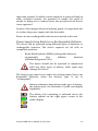
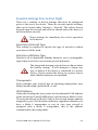
Fault Reporting and other Information
During normal operation the display advises the user on
operational conditions. In addition, the device has a self-test
function. Should it detect a fault, the device will display a fault
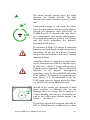
report. Several types of reports might be displayed:
Serious Fault: Operation may not continue.
Caution / Fault: A fault has occurred and/or
extra care is required.
Information: Simple information report, no
fault.
PowerFLARM Device Manual for FW v2.00
21
Operation
The device is operated using the integral turn-button with push
function.
Turn/push-button
The following table gives a brief overview of the most important
push-button combinations.
Brief push on button
Select / Enter
Longer push on button
Open/Close menu
Very long push on button
Switch On/Off
Turn button
Choose zoom depth, or select
object in menu
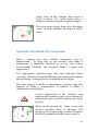
Normal Operation
In normal operation the device shows signals received from other
FLARM-device- or ADS-B-OUT 1090ES targets on a radar-like
display. The user can select different zoom levels by turning the
button.
The large aircraft symbol always indicates the
nearest aircraft and its relative track. Above
the arrow (or below if the nearest aircraft is
below), the relative height in steps of 100 ft
and a small arrow showing climb/descent
information is given. For example: 300ft
higher, flying from left to right descending.
April 3, 2012
22
The small aircraft symbol gives the flight
direction for distant aircraft. The sign
indicates the relative position above or below
you.
Dark green, orange or red circle: the circle
show the approximate distance of the nearest
aircraft not equipped with ADS-B-OUT or
FLARM devices, i.e. aircraft with only ModeC/S transponders and nearby interrogation.
The height information is given in 100 ft steps
and the circle symbolises the distance.
(Example: 600ft above)
The distance to Mode C/S targets is estimated
based on received signal strength and may be
inaccurate. Do not rely on a Mode-C/S target
being at the exact distance indicated. Always
maintain lookout.
Sometimes, Mode A squawks are used which
can be interpreted as a Mode C altitude reply.
In this case, a Mode C target with incorrect
altitude may be displayed. This is a limitation
inherent to the passive interrogation
technology used by PowerFLARM and other
PCAS systems. To minimize the probability of
false alarms, it is recommended to set the
PCAS range values to figures useful for flight,
e.g. 2000ft vertical and 4NM horizontal.
Aircraft in the vicinity are displayed as dark
green symbols of different size. In the
example, there is a target 300 ft above at 2
o'clock, heading towards you, descending; as
well as two other more distant targets, one
below - , one above +.
The nearest aircraft not equipped with ADS-BOUT or FLARM devices, is indicated as a dark
PowerFLARM Device Manual for FW v2.00
23
green circle, in the example, that target is
2400 ft below. The circle radius gives a
distance estimation based on signal strength.
The circle turns orange, then red as the target
closes in. In the example, the target is 200 ft
above.
Operation with Mode S/C transponder
Mode C signals only carry altitude information, but no
identification. To avoid that an the aircraft’s own Mode C
transponder is constantly displayed as a very close target,
PowerFLARM identifies the strongest Mode C signal and
suppresses it.
The suppression requires some time and sufficient Radar
coverage. Therefore, PowerFLARM may only detect and suppress
the own Mode C transponder a few minutes into the flight.
This also applies to Mode S transponders, because they also
function as Mode C transponders in addition to Mode S
(backwards compatibility).
Correct suppression of the aircraft’s own
transponder depends on the correct setting of
transponder type and ICAO address (in case of
Mode S).
When on the ground, the 'radar' screen will
operate provided there is adequate GPS
reception. The screen image is then oriented to
the North, symbolised in the screen by an 'N'.
April 3, 2012
24
Collision Warnings
Warning Presentation
If a dangerous situation is recognised during normal operation,
the device gives an appropriate warning. The target image
displayed is adjusted in accordance with the nature of the threat.
Large orange coloured aircraft symbol: this
aircraft poses a threat of collision. The flight
direction and height difference of the other
aircraft are given to the nearest 100 ft,
together with an indication of climb/descent.
In this example: 300 ft higher, descending,
flying from left to right.
Very large red aircraft symbol: there is an
immediate threat of collision. In addition, the
display gives an indication of the vertical
angle to the other aircraft. The flight direction
and height difference of the other aircraft are
given to the nearest 100 ft, together with an
indication of climb/descent. In this example:
300 ft higher, descending, flying from left to
right.
In dangerous situations, aircraft posing a
threat are presented in orange or red,
depending on the urgency of the threat. An
acoustic warning is issued in addition to the
optical warning.
In very dangerous situations the zoom factor
is automatically adapted to an appropriate
value.
PowerFLARM Device Manual for FW v2.00
25
Depending upon the threat level, the acoustic warning varies the
bleeper frequency.
Information about Warnings
If there are several fixed or moving objects within radio range, the
device uses a mathematical algorithm to determine that which
poses the most immediate threat, and issues a warning about this
threat and none other. The pilot is unable to acknowledge the
warning. However, in spite of a warning having been given for a
single object it remains possible that several, or other objects
simultaneously represent a major threat, or in effect are together
more dangerous than the object for which the warning was issued.
If the device simultaneously detects a threat from a moving object
and a fixed object, then a warning is issued for that which
represents the earliest threat of collision.
On the basis of calculation the device indicates the direction taken
by the most dangerous object, and its current location. The device
does not indicate where the closest proximity may occur, nor what
avoiding action is required. Whether and what avoiding action
should be taken is the sole responsibility of the pilot, whose
correct response must be based upon his own observation of the
local airspace. In particular, he must observe the avoidance rules
of the air, and ensure that the avoidance action does not endanger
any other airspace users. Depending upon the flight phase, the
device uses different forecast processes, movement models and
warning calculations to provide the pilot with the best possible
support without distraction. For example, sensitivity is reduced
when a sailplane is thermalling. These models and processes are
optimised, but always represent a compromise. As seen by the
pilot, these models will issue 'unnecessary' warnings; in other
words the device may give a warning in situations where there is
no subjective danger. It is also possible that the device will not
give warning of the most serious threat, or gives no warning at all.
Warnings are given at very short notice, normally up to 20
seconds prior to the closest calculated proximity. The intensity of
the warning indicates the threat level (calculated collision time)
but not the geometric distance. The device only issues a warning if
it calculates and predicts a considerable threat of collision. It is
April 3, 2012
26
thus possible that although a signal is received, that no report is
issued about the presence of another aircraft.
Settings Menu
The settings menu is called up by extended push of the button.
The user then navigates his way through the menu by rotating the
button. A short push on the button selects the item that is
currently highlighted.
On top of each menu, a push returns to the previous level. You
may quit the menu by a long press of the button at any time.
PowerFLARM Device Manual for FW v2.00
27
Menu Structure
The following diagram shows the device menu sequence.
Volume
Volume for warning buzzer and Audio out jack
Settings
Aircraft
Type: Selection of aircraft type
ICAO Address: Enter ICAO Address (hex Mode S Code)
XPDR: Own transponder details
FLARM
Range: FLARM-device range
PCAS
Range: Horizontal range Transponder Receiver
Vertical Range: Vertical Range Transponder Receiver
Mode C: Select/deselect processing of Mode C targets
ADS-B
Range: Horizontal Range ADS-B-IN
Vertical Range: Vertical Range ADS-B-IN
Data-Port
Baud Rate: Set data rate for RS232 data output
Sentences: Selection of data issued
Brightness
Brightness Setting
Audio Out
External head-set
Batteries
Battery type
Factory Reset
Return to factory settings (Note: There is NO confirmation screen)
Info
About
Version and hardware information
System
System parameters
Update
Firmware update from SD card
Repair
Recovery sequence for firmware update
Diagn. File
Write diagnostic data to SD card
Power Off
April 3, 2012
Switches device off
28
Essential Settings Prior to First Flight
There are a number of device settings that must be configured
prior to the use of the device. These are aircraft-specific settings,
that can be found under 'Settings > 'Aircraft'. The values chosen
depend upon the aircraft and must be altered before the device is
used in another aircraft.
These settings are mandatory for correct operation
of the device.
Selection of Aircraft Type
This setting is required to specify the type of aircraft in which
your device will be used.
Selection of Battery Type
Default is set to disposable Alkaline batteries, set to rechargeable
type if that is used for correct battery level indication.
The integrated charging circuit does not know about
the battery setting. It will attempt to charge any
type of battery if the device is connected to a power
source. Never connect the device to a power source
when Alkaline batteries are installed.
Transponder
Select whether your aircraft has an operating transponder (any
Mode) installed and switched ON, or not.
ICAO Address
Under this heading the user enters the hexadecimal ICAO address
of the aircraft in PowerFLARM device, also known as Mode S Code.
The aircraft address or Mode S Code is the aircraft-unique address
assigned by your Civil Aviation Authority, regardless whether you
have a Mode S transponder or not; in case your aircraft is
equipped with a Mode S transponder, this is the address
transmitted by the transponder.
PowerFLARM Device Manual for FW v2.00
29
The aircraft's ICAO address is found in the aircraft documents, in
the USA, consult
registry.faa.gov/aircraftinquiry/NNum_Inquiry.aspx .
Make sure to use the 6-digit hexadecimal number, not the 8-digit
octal
number,
for
number
transformation
consult
www.kloth.net/radio/icao24lookup.php . Don’t truncate the first
6 digits of an 8-digit octal address to the 6-digit hex address! In
the US, addresses are always in the range between hex A00000
and AFFFFF (equivalent to octal addresses between 50000000
and 53777777).
Incorrect settings will result in false warnings or
a failure of the warning function. This also
applies to your Mode S/ADS-B transponder (if
installed).
Both PowerFLARM and the
transponder must be set to the correct address.
Register your hex ICAO address for free at www.flarmnet.org
Legal Notes
Product Warranty
The warranty is immediately cancelled should the device be
opened, misused, faulty installation, and any breach of copyright.
Limitations
The device has been designed as a non-essential 'situation
awareness only' device, whose task is solely to support the pilot; it
is not always in a position to provide a reliable warning. In
particular, the device does not provide any suggestions as to
avoiding action. Under no circumstances does the device facilitate
a change in flight tactics, user or commander response. Even
though you have installed the device, you remain responsible and
liable for the safety of all passengers and other aircraft. Operation
of the device is solely a matter at the discretion of the user and
commander. The device may only be operated by persons who
have made a careful study of the user instructions.
April 3, 2012
30
The device can only warn of the presence of other aircraft that are
equipped with PowerFLARM devices or compatible equipment,
and of obstacles that are recorded in the internal data bank. The
device does not communicate actively with A/C/S transponders,
and is therefore not detected by ACAS/TCAS/PCAS or Air Traffic
Control. Likewise, the device does not communicate actively with
TIS-B, FIS-B and ADS-B (1090ES, UAT, VDL-4).
The device has not undergone the conventional aeronautical
certification process. Software development was conducted in
accordance with the usual standards and procedures required for
industrial electronics products. The optional obstacle data bank in
the device is not certificated. The use of public access unlicensed
radio bandwidths in the air is subject to a number of limitations,
with some national differences. The pilot and user of the device
are solely responsible that the device is operated in accordance
with the valid local regulations.
FLARM Technology GmbH reserves all rights to this document and
the information contained herein. The redistribution of this
document as a whole without modification is permitted. Copyright
© 2011.
FLARM is a registered trademark in the European Union and other
territories and used under license by FLARM Technology GmbH.
PowerFLARM, the FLARM logo and the PowerFLARM logo are
trademarks, used under license by FLARM Technology GmbH.
Other marks are the property of their respective owners and are
used here only for identification purposes.
Legal Liability
FLARM Technology GmbH, also its agents, designers, component
suppliers, manufacturers and data suppliers accept no legal
liability or responsibility for damage or legal claims.
Users agree to indemnify and hold harmless FLARM Technology
GmbH, its officers, subsidiaries, affiliates, and their respective
successors and assigns, from and against all third party claims,
loss, damage or expense, and any other liabilities whatsoever,
PowerFLARM Device Manual for FW v2.00
31
which may be incurred by FLARM Technology GmbH with respect
to any product from FLARM Technology GmbH.
In addition, FLARM Technology GmbH's current General Terms
and Conditions of Sale apply.
FLARM Technology GmbH makes no warranties based on the
accuracy or completeness of the contents of this document and
reserves the right to make changes to specifications and product
descriptions at any time without notice.
Conformity Declaration
FLARM Technology GmbH, Lindenstrasse 4,
CH-6340 Baar, Switzerland, declares that the
product PowerFLARM Collision Warning
Device in Hardware Version FLAPFP2*E and
typical configuration, meets the requirements
of the CE mark.
The communications conformity meets the
requirements of EN 300 220 (power class 9),
EMC- Conformity EN 301 489 (class 3 SRDDevice, equipment type I). The device is in
accord with the requirements of the
European R&TTE Directive.
This device complies with Part 15 of the FCC.
Operation is subject to the following two
conditions: (1) this device may not cause
harmful interference, and (2) this device must
accept any interference received, including
interference that may cause undesired
operation.
FCC ID:
ZKUGC625161
Within the USA, the device may only be used
in transportation vehicles such as aircraft or
motor vehicles.
This Class A digital apparatus complies with
Canadian ICES-003.
April 3, 2012
IC ID Number:
10154A-FLAPFP24
32
Cet appareil numérique de la classe A est
conforme à la norme NMB-003 du Canada.
RF Radiation Hazard Warning
To ensure compliance with FCC and Industry Canada RF exposure
requirements, this device must be installed in a location where the
antennas of the device will have a minimum distance of at least 30
cm (12 inches) from all persons. Using higher gain antennas and
types of antennas not certified for use with this product is not
allowed. The device shall not be co-located with another transmitter.
Installez l'appareil en veillant à conserver une distance d'au moins
30 cm entre les éléments rayonnants et les personnes. Cet avertissement de sécurité est conforme aux limites d'exposition définies par
la norme CNR-102 at relative aux fréquences radio.
Maximum Antenna Gain
Currently, the maximum antenna gain for external antennas is
limited to 5.2dBi for operation in the 2400MHz to 2483.5MHz,
5150MHz to 5250MHz and 5725MHz to 5825MHz bands. The
antenna gains must not exceed maximum EIRP limits set by the
FCC / Industry Canada.
Actuellement, le gain d'antenne maximal d'antennes externes est
limité à 5.2dBi pour un fonctionnement en 2400MHz à 2483.5MHz,
5150MHz à 5250MHz et 5725MHz à 5825MHz par points à bandes.
L'antenne gain doit pas être supérieure à maximum EIRP limites
fixées par la FCC/Industrie Canada.
Industry Canada Notice and Marking
Under Industry Canada regulations, this radio transmitter may
only operate using an antenna of a type and maximum (or lesser)
gain approved for the transmitter by Industry Canada. To reduce
PowerFLARM Device Manual for FW v2.00
33
potential radio interference to other users, the antenna type and
its gain should be so chosen that the equivalent isotropically radiated power (e.i.r.p.) is not more than that necessary for successful
communication.
Conformément à la réglementation d'Industrie Canada, le présent
émetteur radio peut fonctionner avec une antenne d'un type et d'un
gain maximal (ou inférieur) approuvé pour l'émetteur par Industrie
Canada. Dans le but de réduire les risques de brouillage radioélectrique à l'intention des autres utilisateurs, il faut choisir le type
d'antenne et son gain de sorte que la puissance isotrope rayonnée
équivalente (p.i.r.e.) ne dépasse pas l'intensité nécessaire à l'établissement d'une communication satisfaisante.
This device complies with Industry Canada licence-exempt RSS
standard(s). Operation is subject to the following two conditions:
(1) this device may not cause interference, and (2) this device
must accept any interference, including interference that may
cause undesired operation of the device.
Le présent appareil est conforme aux CNR d'Industrie Canada applicables aux appareils radio exempts de licence. L'exploitation est
autorisée aux deux conditions suivantes : (1) l'appareil ne doit pas
produire de brouillage, et (2) l'utilisateur de l'appareil doit accepter
tout brouillage radioélectrique subi, même si le brouillage est susceptible d'en compromettre le fonctionnement.
April 3, 2012
34