1
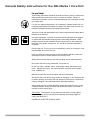
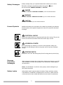
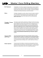
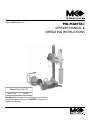
www.mkdiamond.com MK-MANTA I OWNERS MANUAL & OPERATING INSTRUCTIONS Manual Part #161115 Revision 201 11.2008 Caution: Read all safety and operating instructions before using this equipment. This parts list MUST accompany the equipment at all times. MK Diamond’s Manta I Core Drill - Operators Manual General Safety Instructions2 Safety Messages and Symbols3 Hazard Symbols3 Damage Prevention Messages3 Safety Labels3 Drill Features Motor4 Carraige, Column and Base4 Vacuum Base and Pump4 Water System4 Unpacking 5 Assembly Main Assembly6 Feed Handle and Meter Box 6 Vacuum Base Gasket6 Final Assembly6 Drilling Operations Electrical Requirements7 Grounding7 Extension Cords7 Securing the Rig8 Drilling Speeds9 Drilling Pressure and the Ammeter 9 Water Supply9 Carraige Rigidity 10 Shear Pin and Clutch Protection 10 Mounting Bits 10 Drilling Procedure 10 Deep Drilling 12 Maintenance Cleaning 12 Vacuum Base Gasket12 Trouble Shooting13 Warranty Information14 Exploded View & Parts List Exploded View15-18 Parts List19-21 MK Diamond Authorized Service Center Back Cover How to Order Repair Parts Back Cover Returned Merchandise PolicyBack Cover 1 General Safety Instructions for the MK-Manta I Core Drill on For your Safety! These safety precautions should be followed at all times. Failure to follow these safety precautions could result in injury to yourself and others. Safety is a combination of operator common sense and alertness at all times when this drill rig is being used. For your own safety and protection, do not attempt to operate the drill until it is completely assembled and installed according to the instructions, and until you read and understand all safety and operating instructions. Take time to read and understand fully the owners manual and all safety labels attached to the core drill. Use safety equipment. Everyone in the work area should wear safety goggles or glasses with side shields complying with current safety standards. Wear hearing protection during extended use and a dust mask for dusty operations. Hard hats, face shields, safety shoes, etc. should be used when specified or necessary. ) (( Use the right tool.) Do not use a tool or attachment to do a job for which it is not recommended. Do not alter the tool. Keep your work area clean and safe to avoid accidents. Maintain a safe zone and keep all visitors at a safe distance from the work area. Always insure that the switch is off before plugging unit into electrical power. Never leave the drill running unattended. Turn power off. on Do not over reach, maintain control. Keep proper footing and balance at all times. Maintain a firm grip. Use extra care when using the tool on ladders, roofs, scaffolds, etc. Maintain all tools with care for the safest and best performance. Should any part of this drill become missing or damaged, or any component fail to perform properly, shut off the drill and unplug the power source. Replace the missing, damaged, and/or failed part before resuming operations. Always keep alert. Do not allow familiarity (gained from frequent use) to cause a careless mistake. Always remember that a careless fraction of a second is sufficient to inflict serious injury. Think Safety The operation of any power tool can result in foreign objects being thrown into the eyes causing severe damage. Use safety goggles to comply with ANSI Z87.1. FORESIGHT IS BETTER THAN NO SIGHT (( )) 2 Safety Messages A safety message alerts you to potential hazards that could hurt you or others. Each safety message is preceded by a safety alert symbol ( ) and one of three words: DANGER, WARNING, or CAUTION. DANGER You WILL be KILLED or SERIOUSLY INJURED if you do not follow directions. WARNING You CAN be KILLED or SERIOUSLY INJURED if you do not follow directions. CAUTION You CAN be INJURED if you do not follow directions. Hazard Symbols Additional information as to the nature of the hazard is provided by the following hazard symbols, which appear throughout the manual in conjunction with safety messages. ELECTRICAL SHOCK! Never touch electrical wires or components while the drill is running. They can be sources of electrical shock which could cause severe injury or burns. on ACCIDENTAL STARTS! Before performing any maintence or service on this equipment, always turn the switch off and unplug the drill from the power source to prevent accidental starting. ROTATING PARTS! Keep hands, feet, hair, and clothing away from all moving parts to prevent injury. Damage Prevention Messages Other important messages that are designed to help prevent damage to your MK Diamond Manta Core Drill, other property, or the environment, are preceded by the word notice. Notice: Your MK-Manta I Core Drill or other property could be damaged if you don’t follow instructions. (( Safety Labels )) Safety labels contain important safety information. Please read them carefully. These labels are considered a permanent part of your drill. If a label comes off or becomes hard to read, contact MK Diamond or your dealer for replacement. 3 Manta I Core Drilling Machine Drill Features The MK-Manta I Core Drill is a powerful all-purpose drilling rig that is designed to drill holes, up to 12 inches in diameter (14 inches with the 2 inch spacer), in all types of concrete slabs, floors, walls, and ceilings. The Manta is designed for easy anchoring using masonry anchors. A secondary vacuum base is provided to facilitate quick and easy anchoring to smooth floor surfaces. Motor The Manta is designed for use with a variety of motors. All motors are powerful two or three speed units that provide the correct cutting speed over a range of diamond drill sizes. Some models utilizes a shear-pin system for motor protection, while some others utilize a slip-clutch. See the Drilling Speeds section of this manual. Carraige, Column and Base The carraige, column and base assembly of the Manta I Core Drill is the strong, sturdy drilling platform that provides the rigidity needed to quickly drill accurately placed, straight, smooth holes in all types of concrete. The Manta’s base is slotted to provide easy anchoring of the drill, in a variety of drilling situations, with a single masonry anchor. The slot also allows more than one hole to be drilled from a single anchor location. The base contains four leveling screws to insure accurate hole alignment even on uneven concrete surfaces. The base also has a cast in handle and a set of wheels to provide easy transport.The carraige travel is controlled by a strong rack and pinion gear-system, that can be locked at any point on the column. The slidding handle allows the operator to easily control the drilling pressure and speed. At the top of the column is a strong jack-screw that allows for additional bracing to overhead or opposite surfaces. Vacuum Base and Pump The vacuum base and pump provide quick and reliable mounting to smooth concrete slab and floor surfaces. The powerful vacuum pump provides 25 PSI of holding power which equates to over 1800 pounds of force, holding the Manta securely, for safe, accurate drilling. The pump has a quick disconnect connector on the hose, as well as an ergonomic handle, to provide ease of transport. The vacuum base also features leveling screws, a cast-in handle and six inch (6”) wheels. Water System The water system for the Manta is a simple hose hook-up and shut-off valve that provides water under pressure to the diamond drill bit. The water travels to the center of the bit through the water swivel and spindle to insure that water is supplied to the cutting end of the bit, even in deep drilling operations. 4 Unpacking Carefully cut through the carton approximately 6 inches from the bottom using a box cutter or other safety knife, and lift away the top portion of the box. Remove the Accessory Pack, Vacuum Pump and Manta Core Drill. Open the accessory pack and check each item with the contents list and illustration below, making certain that all items are accounted for and in good condition before discarding any packing material. If there are any missing or damaged parts, call our toll free number 1-(800)-421-5830 for instructions before proceeding with the assembly. CONTENTS Contents of the carton: Manta (including column, carraige, both bases and motor), Vacuum Pump and Accessory Pack. In the Accessory Pack you will find: Control box, leveling screws (8), feed handle (1) and knobs (2), vacuum base gasket, wrench, Manta manual, Manta warranty card, motor manual and motor warranty card. Manta and Vacuum Pump Control Box Vacuum Pump Leveling Screws Base Gasket Feed Handle and Knobs Manta Manual 5 Warranty Card Assembly WARNING For your own safety and protection, do not attempt to operate this drill until it is completely assembled and installed according to these instructions, and until you understand the machines capabilities and the potential hazards associated with it. Main Assembly Step 1 The Manta I is shipped with the main part of the Manta mounted backwards on the Vacuum base. Remove the nut and bolt that hold the main assembly to the Vacuum base observing the following precaution. Turn the Vacuum base around to the correct orientation, slide the small base all the way back on the vacuum base, and reinstall the nut and bolt. CAUTION When removing the nut and bolt that holds the main assembly to the vacuum base, the Manta will tip forward. Be sure to hold the Manta when removing the vacuum base. To set the Manta so that it will stand up, loosen the carraige lock knob (be sure to hold the carraige) and move the carraige down to a position where the end of the motor spindle just touches the ground. Step 2 Install the leveling screws (8), screwing four (4) into each base. Feed Handle and Meter Box Step 3 Install the feed handles (1) and knobs (2) by screwing one knob onto the end of the handle, then slip thru hub and attach other knob. Step 4 Remove the Manta from the vacuum base by removing the nut and bolt that holds the main assembly to the vacuum base. Set the Manta aside, observing the following precaution. Vacuum Base Gasket Turn the vacuum base over. Press the gasket into the groove in the underside of the base. The gasket is cut, at the factory, to the correct length, so that the two ends will butt together once the gasket is installed. Final Assembly Step 5 Assemble the two pieces of the water valve, and install the valve, into the water swivel, on the motor, just above the spindle (see motor literature). Plug the cord from the motor into the upper outlet on the meter box (the one opposite the motor on-off switch. The other outlet on the meter box is for the vacuum pump. 6 Drilling Operations Electrical Requirements Grounding The MK-Manta I Core Drill rig has been equipped with either a 20 Amp/115V 3 speed motor, a 20 Amp/120V 2 speed motor, or a 15 Amp/115V 2 speed motor. The drill should be used on an electrical circuit, separate from other loads, and protected by a 30 amp circuit breaker. NEMA L5-20 125 V, 20 Amp Locking Plug and receptacle The MK-Manta I has been provided with a 20 Amp plug (NEMA 15-20) or a 30 Amp (NEMA 15-30) locking plug depending on the model. Grounding blade Cover of grounded outlet box NEMA L5-30 125 V, 30 Amp Locking Plug and receptacle Grounding blade Cover of grounded outlet box The MK Manta is marked “Grounding Required” and has a three wire cord and three prong grounding plug. The plug must be connected to a properly grounded outlet (see figure below). If the tool should electrically malfunction or break down, grounding provides a low resistance path to carry electricity away from the user, reducing the risk of electrical shock. The grounding prong in the plug is connected through the green wire inside the cord to the grounding system in the tool. The green wire in the cord must be the only wire connected to the tool’s grounding systems and must never be attached to an electrically live terminal. Your tool must be plugged into an appropriate outlet, properly installed and grounded in accordance with all codes and ordinances. The plug and outlet should look like those in the figure to the left. WARNING Improperly connecting the grounding wire can result in the risk of electric shock. Check with a qualified electrician if you are in doubt as to whether the outlet is properly grounded. Do not modify the plug provided with the tool. Never remove the grounding prong from the plug. Do not use the tool if the cord or plug is damaged. If damaged, have it repaired by an authorized service facility before use. If the plug will not fit the outlet, have a proper outlet installed by a qualified electrician. The use of a circuit protected by a ground fault interrupter (GFI) is highly recommended. Use extension cords of the proper cable size, referring to the following chart. Extension Cords Cord Length 25 feet 50 feet 75 feet Wire Size (AWG) #10 #8 #6 WARNING Never use an extension cord smaller than shown in the chart. Be sure your extension cord is properly wired and in good electrical condition. Always replace a damaged extension cord or have it repaired by a qualified electrician before using it. Protect your extension cords form sharp objects, excessive heat and damp or wet areas. Notice: Using an extension cord with inadequately sized wire causes a serious drop in voltage, resulting in loss of power and possible tool damage. 7 Securing the Rig Recommended Methods A. Use a concrete anchor. Use either a 1/2 or 5/8 concrete anchor to secure the base to the work surface. Always be sure to level the rig. Using a concrete anchor, insert a bolt through the slot located on the base and tighten the bolt firmly in the anchor. WARNING It is essential to always secure the rig to the work surface to help prevent personal injury and also to protect the rig. An unsecured rig could rotate during drilling and possibly cause injury. It could also cause the bit to chatter against the work surface or bind in a hole, which can fracture the diamond segments. B. Vacuum base. The MK-Manta I Core Drill Rig is equipped with a vacuum base. This base is designed to provide approximately 1800 pounds of total holding power. In order to provide the most rigidity to your core rig the unit should be used on a relatively smooth surface such as concrete. (If the surface is too porous or rough the vacuum mount may not hold securely.) 1. Turn the vacuum pump on and step on the vacuum base until a vacuum is created and the base adheres to the work surface. 2. Level the rig using the leveling bolts. Use a minimum amount of adjustment to the leveling bolts to avoid breaking the vacuum seal. The vacuum gauge should read approximately 25 pounds per square inch (PSI) of pressure. If the gauge reads 20 PSI or less, check the work surface for conditions which may interfere with adequate suction such as cracks, dirt or debris on a porous surface. WARNING Do not drill if the gauge reads less than 20 PSI. Do no use vacuum base on cracked, uneven, porous or vertical surfaces. C. Additional support. For added rigidity, you may use a telescoping extension assembly in conjunction with a concrete anchor or vacuum base. To use a telescoping assembly, first level the rig with the leveling screws. Secure the rig with an anchor or the vacuum base. Place the top flange of the extension against a ceiling or wall and place the other end on the jack screw of the column. The assembly is adjustable up to 14 feet. Use the jack screw to tighten the assembly and to make small adjustments. The MK-Manta I features two speed motors by Milwaukee and a three speed motor by Eibenstock. Specifications for the different motors are listed in the following table. 8 Drilling Speeds Manufacturer Model # AMP Volts Speed(RPM) Eibenstock EBM 300/3 P 20 120 Milwaukee 4004 20 120 Milwaukee 4090 15 120 Milwaukee 4094 20 120 Milwaukee 4096 20 120 Milwaukee 4097-20 15 120 Low – 270 Medium – 700 High – 1250 Low – 300 High – 600 Low – 375 High – 750 Low – 450 High – 900 Low – 450 High – 900 Low – 500 High – 1000 Suggested Dia. in Medium Aggregate Low – 4” Medium – 2”-6” High – 3/4”-4” Low – 4” High – 14” Low – 5”-8” High – 2 1/2”-5” Low – 6”-10” High – 2”-6” Low – 6”-10” High – 2”-6” Low – 1 1/4” High – 5” The MK-Manta I will operate in either a high or low gear speed. This speed combined with applied pressure provides the cutting action for the core bit. Speed selection and pressure are determined by hardness of material, aggregate size and grade of diamond core bit. Generally, harder material and larger aggregates require more speed and pressure. Use low speed for large diameter bits and high speed for small diameter bits. Changing of the speeds is accomplished by using the speed shift lever built into the gear case. LOW Notice: Change the gears only when the motor is off. HIGH Drilling Pressure and the Ammeter AMPS 15 18 20 Water Supply All building materials and work surfaces are composed of aggregate of various size. Aggregates are materials such as gravel or crushed stone. The size of the grains and the hardness of the material affects the speed of drilling. Most building materials contain some type of steel reinforcements. All MK bits are designed to cut through these types of reinforcing steel. However, bits should never be used for drilling solid steel plates. Proper selection of the diamond core bit should be based on material to be drilled and performance requirements. Steady, even pressure assures accurate holes and longer bit life. Always maintain consistent pressure so that the bit is constantly cutting. Notice: Too much pressure will damage the bit and motor. Too little pressure will glaze over the diamonds, reducing cutting efficiency and prematurely wearing the bit. The ammeter is the gauge on the Control Box. It provides pressure feedback information during drilling, allowing the operator to help prevent motor overload and premature bit wear. The green area is the operating range, and the red area is the overload range. Generally, the operator should keep the ammeter needle in the upper area of the operating range for large diameter bits, and in the lower green area for small diameter bits. If the bit contacts steel reinforcing rods, the needle on the ammeter may jump slightly showing a heavier load. If this occurs, do not decrease pressure or you may damage the diamonds. The Manta may be operated with the ammeter needle into the red area for the short period of time that it takes to cut through a steel rod. An adequate supply of clean water is necessary for drilling. Connect the water supply hose to the hose fitting on the output of core drill motor. Take precautions that the water supply will not be interrupted during the drilling operations. Notice: If a bit is run dry it can be ruined in a few seconds. 9 Carriage Rigidity Shear Pin and Clutch Protection Mounting Bits It is essential that the carraige fits snugly on the column to prevent the motor or bit from wobbling during drilling. Through normal use the carraige may loosen from the column and begin to wobble. Before drilling, always make sure the carraige is rigid by trying to wiggle it with your hand. If the carraige is secure it should not move. If it does move, tighten the adjustment screws for the nylon gibs that secure the carraige to the column. Tighten only enough to remove the play. Do not over tighten. The MK-Manta I Core Drill uses either a shear pin or a friction clutch to protect the gear and motor against overload. The shear pin drives the outer portion of the drive spindle. If the motor should overload the pin will shear. Extra shear pins are supplied or can be ordered from MK Diamond’s Customer Service. Tighten only enough to remove the play. Do not over tighten. Another model features a friction clutch rather than a shear pin to protect the motor and gears. If the motor overloads the clutch will begin to slip and the bit will stop rotating. The clutch is factory-set and does not require adjustments. However, under normal use, the clutch may start to slip at low torque. If this happens, refer to the motors Owner’s Manual. Bits with permanently attached adapters simply screw directly onto the threads of the drill spindle. Ensure that the end of the bit butts up squarely against the shoulder on the spindle. The MK-Manta I has a 1 1/4”-7 thread. For bits with other threads, use a shaft coupling. After a bit has been mounted, turn the power on and check that there is a minimum of run-out or wobble. WARNING To reduce the risk of injury, always unplug tool before attaching or removing accessories. Only use specifically recommended accessories. Others may be hazardous. Drilling Procedure WARNING When drilling through concrete floors, the core will generally drop from the diamond bit. Caution should be provided for people and property below the drilling area. 1. Ensure that you have read and fully understand the complete operation of the MK-Manta I you have purchased prior to commencing drilling operations. 2. Select and install a diamond core bit appropriate for the job. Note: Grease the bit threads to help prevent the bit from seizing on the spindle due to rust. 3. Select either high or low gear speed according to the chart in the Drilling Speeds section of this manual. (Do not shift speed when motor is on.) 4. Connect water hose to water swivel. 5. Secure the rig as described in the Securing the rig section of this manual. 10 WARNING If using the vacuum base, do not continue operations unless the vacuum gauge reads more than 20 inches of mercury. Normally, the gauge will read 23 inches or more. 6. Turn the motor switch on the Control box ON. Turn the water ON so that an adequate flow of water is supplied through the water swivel, to the bit. Hold the handle and slightly loosen the carriage lock knob. Slowly rotate the handle to lower the bit into the work piece - apply steady even pressure. Note: To prevent the bit from wandering, always use a light load to start the hole and wait for the diamond tip of the bit to penetrate the work surface before increasing the load. 7. Use consistent pressure so that the bit cuts consistently. Insufficient pressure will cause the diamond core bit to glaze over. Too much pressure will overload the motor and crush the diamonds. Use the ammeter on the Control box as a guide for proper pressure. CAUTION If the rig shifts during drilling, stop the motor, reposition the rig, and resume drilling. 8. Monitor the water flow. If the water flow is adequate, the water leaving the cut should be slightly sludgy. When cutting metal rebar, the water should have a gray metal coloring. Notice: When drilling into prestressed concrete the bit may cut into the hardened steel cable under tension. As the bit cuts through each strand, the tension in the cable is released. The diamond segments on the bit crown can be damaged by the loose wires. The best prevention for bit damage is to use a core bit designed especially for drilling in prestressed concrete. 9. When the cut is complete, keep the drill motor on and rotate the handle to bring the bit up out of the hole. The bit may become stuck if the motor is turned off before the bit is completely clear of the hole. Once the bit is clear of the hole, tighten the carraige lock knob, turn off the motor and the water supply. Note: Normally the core will drop out of the bit, and remain in the hole. However, in cases where the core sticks in the bit, it is sometimes necessary to push the core up and down with the water running to allow the core to drop out. Sometimes very light tapping on the barrel of the bit with a piece of wood will loosen the core. CAUTION Perform this action only with the motor turned off and the unit unplugged to prevent accidental starting and injury. Exercise extreme caution in hand placement when removing a stuck core, as it can be heavy and inflict injury. 11 Deep Drilling When drilling holes that are longer than the core bit, follow the steps below. 1. Begin drilling the hole as usual. When you have drilled to the length of the bit, retract the bit from the hole and turn off the motor and water as usual. 2. Break off the core by driving a chisel or slender wedge into the circular kerf. Remove the core using core tongs, bent music wire or anchor bolts. 3. After removing the core, insert the bit carefully into the hole, attach a bit extension to the bit and core drill rig, then continue drilling as usual. Periodic maintenance, including cleaning, lubrication and inspection for wear and damage are routine servicing procedures. Following the procedures as outlined can prevent serious damage or malfunctioning of the machine, and aid in preserving the useful life of core drill bits. Maintenance on CAUTION Before performing any maintenance to the MK-Manta I, always unplug the unit from the electrical power source. Be sure the On-Off switches are in the Off position, after servicing, and before plugging the unit back in. Cleaning Clean the machine after use, being careful to remove dust and slurry from the motor, vents, carraige and column. Keep tool handles clean, dry and free of oil and grease. Use only mild soap and a damp cloth to clean this tool since certain cleaning agents and solvents are harmful to plastics and other insulated parts. WARNING Never use flammable or combustible solvents around tools. )) Through normal use, the rubber gasket on the underside of the vacuum base can become worn, requiring replacement. Periodically check the gasket for wear. If replacement is required, clean the groove in the base before installing a new gasket. (( Vacuum Base Gasket 12 Troubleshooting PROBLEM When trouble occurs, be sure to check the simple causes which, at first, may seem too obvious to be considered. Refer to the table below for problems and their possible causes. WHAT TO DO? INDICATION CAUSE 1. Check fluid return. Fluid not muddy. Evidence of steel cuttings Drilling in steel reinforcement Speed not correct for the bit size used 2. Check motor speed range Low Penetration Rate Under Prevailing Drilling Paramters Bit worn out. 3. Check wear picture of bit face Diamond without exposure. (flush with matrix) Face of bit plugged with cuttings Face of bit covered with steel Steel cuttings stick to bit face. Wear picture of polished diamonds Heavy Wear at Steel Tube Deep grooves. Heavy Wear. No return of fluid SOLUTION/ RECOMMENDATIONS Adjust drilling parameters to recommendations for reinforcement See recommended speeds Replace with new bit Insufficient bit load Rotated with high RPM on reinforcement Loose material at bottom of hole Not enough fluid pumped. Cuttings burnt to matrix. Diamonds prevented from cutting Steel cuttings stick to bit face. Diamonds prevented from cutting Increase bit load Reduce RPM, or resharpen bit Break core, clean bottom of hole or reduce RPM and drill with increased bit load Clean bit face by sharpening methods such as drilling dry at low RPM in a concrete block 3/8” deep max. Increase water flow rate Clean bit face by drilling in concrete block. Reduce RPM Bit load too low Increase bit load Bit speed too high Use lower speed; increase bit load Worn or open guide ways on cradle. Borehole is getting undulated Adjust guidance on carraige Protruding steel. Spindle is offset. Bit out of true Adjust guidance on carraige Nicks or dirt on mounting faces Bit is deformed. Replace bit. Poor cleaning of abrasive cuttings. Improve flushing. Crown clearance worn out. Replace bit If Leaking can be tolerated; continue drilling with increased attention. Check where fluid is leaking. 13 PROBLEM WHAT TO DO? INDICATION Loose material (cut steel or aggregates) is blocking between core and bit or between borehole and bit. Bit Stuck 1. Try to raise bit, if impossible: Drill moved during drilling (poor fastening). 2. Stop rotation Bit deviates, guide ways on cradle have too much clearance. No clearance between tube I.D. or O.D. and crown I.D. or O.D. Shear Pin Fail 1. Stop rotation 2. Raise bit Warranty Information Drill impacted to stall at lower speeds. SOLUTION/ RECOMMENDATIONS Step 1: Apply wrench and rotate bit in both directions while bit is under tension. If not successful: Step 2: Try to over drill a hole slightly larger than the stuck bit. Disconnect bit and remove, break core. Start over with improved fastening of machine. Disconnect machine, adjust guidance. Replace bit. Use recommended speed for the bit diameter used. Raise bit when it begins to load down. Feed bit slowly when chattering begins. If within one (1) year from the date of purchase, this MK Diamond drill fails due to a defect in material or workmanship, MK will repair it, free of charge, by returning the unit to the dealer where it was purchased. This warranty DOES NOT cover normal wear or damage resulting from operator abuse. In no event shall MK Diamond Products, Inc. be liable for consequential damages arising out of the failure of any product if operating improperly. Selected components such as motors/engines are excluded from this warranty and are subject to the manufacturer’s warranty. Each manufacturer carries its own warranty conditions which are listed on the literature accompanying the motor/engine at the time of purchase. MK Diamond Products may act as a warranty station for the motor/engine repairs based on individual agreement with the manufacturer. This warranty is in lieu of all other warranties expressed or implied. 14 MANTA I COMBO EXPLODED VIEW AND PARTS LIST EXPLODED VIEW 15 MANTA EXPLODED VIEW (cont...) 16 MANTA EXPLODED VIEW (cont...) 17 MANTA EXPLODED VIEW (cont...) 18 MANTA PARTS LIST PARTS LIST: Item A A1 A2 A3 A4 A5 A6 A7 A8 A9 A10 A11 A12 A13 A14 AA AA1 AA2 AA3 AA4 AA5 AA6 AA7 AA8 AA9 AA10 AA11 AA12 D D1 D2 D3 D4 D5 D6 D7 D8 D9 D10 D11 D12 D13 D14 D15 D16 D17 E E1 E2 E3 E4 E5 E6 Description Assembly, M1 Base, Vacuum Base, M1 Vacuum Screw, ½-13 x 3 ½ Hex Hd. Cap, Full Thread Gasket, Neoprene Fitting, ¼ MNPT x 3/8 Barb Wheel 6” Screw, 1/2 x 1 3/4 Socket Head Shoulder Washer, ½ SAE Flat Foot, Base Support Screw, 3/8-16 x 2 ¼ Hex Head Cap Washer, 3/8 SAE Flat Nut, 3/8-16 Hex Nylok Stud, ½-13 x 4 Clamping Washer, Plate ¼ x 2 x 2 Nut, ½-13 Flange Assembly, M1 Base, Anchor Base, M1 Anchor Screw, ½-13 x 3 ½ Hex Hd. Cap, Full Thread Wheel, Dia. 1 5/8 x 7/8 Sleeve Bearing Screw, ¼-20 x 2.0, Socket Head Cap Foot, Base Support Screw, 3/8-16 x 2 ¼ Hex Head Cap Washer, 3/8 Flat Nut, 3/8-16 Hex Nylok Label, Manta Serial Tag (not shown) Label, Caution, Safety (not shown) Label, MK, Adhesive (not shown) Assembly, Carriage 2 ½” Body, Carriage Shaft, Gear, Short Bearing Plate, Adjustment Slide, Carriage Screw, 6-32 x 1/2 Flat Head Phillips Machine Screw, 6-32 x 3/8 Flat Head Phillips Machine Nut, 6-32 Nylok Hex Knob, Davies ¼-20 x ¾ Washer, ¼ SAE Flat Back, Carriage Screw, 1/4-20 X 1 Socket Head Cap Screw, ¼-20 x 5/16 Socket Head Set Handle, Carriage Screw, 1/4-20 X ¾ Pan Head Phillips Label, MK USA Screw, 1/4-20 X 1 ¼ Socket Head Cap Assembly, Control Box, Fixed, Dual Switch 120V Box, Control, Fixed Cover, Control Box, Fixed, Dual Switch Screw, ¼-20 x ¾ Socket Head Cap Washer, ¼ Split Lock Screw, 10-24 x 5/8 Self Tapping (phillips) Ammeter 120V 19 Qty 1 1 4 1 1 2 2 2 2 2 2 2 1 1 1 1 1 4 2 2 2 2 2 2 2 1 1 1 1 1 1 2 3 8 8 8 8 1 1 1 4 6 1 2 2 4 1 1 1 2 2 6 1 MK p/n n/a 155753 158284 154543 154659 157434 158390 150924 158389 153529 150923 152505 155124 154613 155125 n/a 155755 158284 158396 158458 158394 158389 153529 150923 152505 157730 155576 157914 n/a 155757 158348 137711 157317 157318 154448 157521 157519 151681 151915 157438 151049 154226 157440 157523 154334 159336 158428 158274 158276 152587 152591 153681 154489 MANTA PARTS LIST (cont...) E7 E8 E9 E10 E11 E12 E13 E14 E15 E17 EB EB1 EB2 EB3 EB4 EB5 EB6 EB7 EB8 EB9 EB10 EB11 EB12 EB13 EB14 EB15 EB16 F1 F1 F3 F4 F5 F6 F7 F8 GB GB1 GB2 GB3 GB4 GB5 GB6 GB7 GB8 GB9 GB10 GB11 GB12 GB13 GB14 GB15 GB16 H H1 Switch, Toggle Receptacle, Flanged 15A / 125V Cord, Power Connector, Cord Receptacle Transformer Screw, 6-32 x ½ Pan Head Plug, Twist-lock Wire Harness (not shown) Cover, Toggle Switch Assembly, Control Box, Single Switch 120V Box, Control, Single Switch Cover, Control Box, Single Switch Screw, ¼-20 x ¾ Socket Head Cap Washer, ¼ Split Lock Screw, 10-24 x 5/8 Ammeter 120V Switch, 30A Toggle Cord, Power Connector, Cord ½ Receptacle, Flanged Twist-lock 20A / 125V Plug, Twist-lock Transformer, Current Screw, 6-32 x ½ Pan Head Wire Harness RTV Silicon Adhesive Sealant Cover, Toggle Switch Assembly, Column Manta, Core Drill Column (w/Gear Rack) Screw, 10-32 X ½ Socket Hd. Cap Washer, #10 Split Lock Screw M22 x 1.25 Jack Screw, 1/2-13 X 3 ½ Hex Head Cap Washer, 1/2 Split Lock Washer, 1/2 SAE Flat Assembly, Vacuum Pump w/ Handle 120V Pump, Vacuum 120v Filter, Water Gauge, Vacuum Nipple, 1/4 MNPT X Close Fitting, 1/4 FNPT X 1/4 FNPT X 1/4 FNPT Tee Valve, 1/4” Pettcock Hose, 3/8 I.D. Air Coupler Body, 1/4 FNPT Fitting, 1/4 MNPT X 3/8 BARB Ferrell, Crimp Base, Vacuum Pump Handgrip, 3/4 X 4 9/16 Black Screw, 10-32 X 1/2 Phillips Pan Head Cap Foot, Rubber Screw, 1/4-20 X 3/4 Flat Head Phillips Cap Nut, 1/4-20 Hex Assembly, Handle, Slip Hub, Slip Handle 20 2 1 3’ 1 1 1 2 1 1 2 1 1 1 2 2 6 1 1 3’ 1 1 1 1 2 1 .25 oz. 1 1 4 4 1 2 2 2 1 1 1 1 3 2 1 6’ 1 2 2 1 1 4 4 4 4 1 1 154491 154473 154494 151307 157375 154490 153459 154556 154715 154301 158430 158385 158387 152587 152591 153681 154489 154491 154494 151307 157375 154556 154490 153459 154715 n/a 154301 n/a 158425-2 157525 153684 157445 154574 153524 150924 154741 154475 154476 154477 152598 154497 154488 154656 154617 154659 154660 154495 139949 151052 154496 154657 151893 n/a 157321 MANTA PARTS LIST(cont...) H2 H3 H4 H5 K K1 K2 K3 K4 LA LA1 LB LB1 LD LD1 LE LE1 LF LF1 LJ LJ1 M M1 M2 M3 M4 MA MA1 MA2 MA3 MA4 MB MB1 MB2 MB3 MB4 N N N2 N3 Spoke, Slip Handle Knob, Ball ½-20 Female Screw, 1/4-20 X ¾ Thumb Screw, ¼-20 X 1/4 Socket Head Set Assembly, Accessory Pack (not shown) Carton, Accessory Pack Owner’s Manual, MK-Manta 1 Core Drill Card, Warranty MK Sell Sheet Assembly, Motor, Milwaukee 4094 Motor, Milwaukee 4094 - Shear Pin, 20A/120V Assembly, Motor, Milwaukee 4096 Motor, Milwaukee 4096 - Slip Clutch, 20A/120V Assembly, Motor, Milwaukee 4004 Motor, Milwaukee 4004 - Slip Clutch, 20A/120V Assembly, Motor, Milwaukee 4097-20 Motor, Milwaukee 4097-20 - Slip Clutch, 15A/120V Assembly, Motor, Milwaukee 4090 Motor, Milwaukee 4090 - Shear Pin, 15A/120V Assembly, Motor, Eibenstock EBM 300/3 P Motor, Eibenstock EBM 300/3/P - Slip Clutch, 20A/120V Assembly, ¾” Motor Mount Plate, Hybrid, Milwaukee Casting, Motor Mount Plate, Hybrid Screw, 3/8-16 x 1 ¼, Socket Hd. Cap Key, 3/8 x 3/8 x 5 Screw, ¼-20 x 1.0, Socket Hd. Cap Assembly, ¾” Motor Mount Plate, Hybrid, CB748 Casting, Motor Mount Plate, Hybrid Screw, 3/8-16 x 1 ¼, Socket Hd. Cap Key, 3/8 x 3/8 x 5 Screw, ¼-28 x 1.5”, Socket Hd. Cap Assembly, ¾” Motor Mount Plate, Hybrid, Ebinstock Casting, Motor Mount Plate, Hybrid Screw, 3/8-16 x 1 ¼, Socket Hd. Cap Key, 3/8 x 3/8 x 5 Screw, M8 x 1.25 x 25mm, Socket Hd. Cap Optional Accessories: Assembly, 2”, Spacer Block Milwaukee Spacer Block, 2” Milwaukee Screw, 3/8-16 x 3 ¼, Socket Hd. Cap Key, 3/8 x 3/8 x 5 21 1 2 1 2 1 1 1 1 1 1 1 1 1 1 1 1 1 1 1 1 1 1 1 4 1 4 1 1 4 1 4 1 1 4 1 4 157322 154486 157432 157528 n/a 157323 161115 155859 155333 n/a 154633 N/a 155540 n/a 159263 n/a 159264 n/a 155976 N/a 158754 n/a 158412 157529 157520 151049 n/a 158412 157529 157520 154684 n/a 158412 157529 157520 157530 1 1 4 1 n/a 154721 161118 157520 How To Order Repair Parts please have the following information ready before calling: SERIAL NUMBER OF YOUR SAW MODEL NUMBER OF SAW WHERE PURCHASED AND WHEN PART NUMBER PART DESCRIPTION all parts listed may be ordered from your local distributor or from mk diamond. If the part is not stocked locally, call our toll free number listed below and ask for our customer service department. For technical support call: 1 (800) 474-5594. There is a $25.00 minimum order. Returned Merchandise Policy Should you need to return any product you have purchased from MK Diamond, please observe the following: Our customer service department should be contacted for approval to return merchandise. Merchandise will not be accepted without a RETURNED GOODS authorization number. All returned merchandise must be shipped prepaid to destination. All returned merchandise must have been purchased within the previous 12 months and be in resalable condition. A restocking charge of 15% will be billed. Para Ordenar Partes De Repuesto Sírvase tener lista la siguiente información antes de llamar: Número de serie de la sierra número de modelo de la sierra Dónde y cuando se compró la sierra Número de la parte Descripción de la parte Todas las partes listadas se pueden pedir a través de su distribuidor autorizado o directamente a MK Diamond. Si la parte no está en existencia local, llame al número de teléfono indicado abajo y pida el departmento de atención al cliente. Para soporte técnio, llame al 1-800-474-5594 sin cargo. El pedido mínimo es de $25.00. Política De Devolución De Mercancía En caso de que sea necesrio devolver algún producto que usted haya comprado a MK Diamond, sívase observar lo siguiente: Usted debe dirigirse a nuestro departamento de atención al cliente para recibir una aprobación de devolución de mercanía. No se aceptará mercancía devuelta sin el correspondiente número de pagado hasta su destino. Toda la mercancía devuelta deberá embarcarse con flete meses anteriores y estar en condiciones de poderse vender como nueva. Se aplicará un cargo de 15% por reintegro al almacén. Pour Commander Les Pièces De Rechange VEUILLEZ AVOIR LES INFORMATIONS SUIVANTES AVANT D’APPELER : NUMÉRO DE SÉRIE DE LA SCIE NUMÉRO DE MODÈLE DE LA SCIE DATE ET LIEU D’ACHAT RÉFÉRENCE DESIGNATION DE LA PIÈCE Toutes les pièces indiquées peuvent être commandées auprès de votre distributeur local ou auprès de MK Diamond. Si la pièce n’est pas stockée localement, veuillez appeler notre numéro d’appel gratuit indiqué cidessous et demander le service de la clientèle. Pour support technique, veuillez contacter le 1 (800) 4745594. Un minimum de commande 25,00 dollars US est de rigueur. Politique De Retour De Marchandises Si vous vous trouvez dans l’obligation de retourner un produit dont vous avez fait l’achat à MK Diamond, veuillez suivre les consignes suivantes: Notre service de clientèle devrait être consulté pour approbation avant de retourner toute marchandise. La marchandise ne sera en aucun cas acceptée sans numéro d’autorisation de Marchandises retournées. Toutes les marchandises retournées doivent avoir fait l’objet de l’achat dans les 12 mois précédents et être en état de revente. Une charge de restockage de 15% sera facturée. MK Diamond Products, Inc. 1315 Storm Parkway. Torrance, CA 90509-2803 1 (800) 421-5830 FAX 1 (310) 539-5158 Manual Part No. 161115 Revision 03/05