1
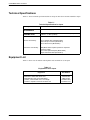
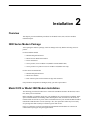
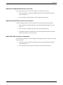
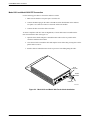
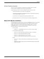
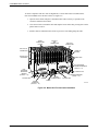
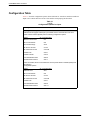
COMSPHERE
3800 SERIES MODEMS
MODELS 3810, 3811, AND 3820
JAPAN SUPPLEMENT
Document No. 3810-A2-GB93-30
COMSPHERE
3800 Series Modems
Models 3810, 3811, and 3820
User’s Guide
Japan Supplement
3810-A2-GB93-30
4th Edition (September 1998)
Changes and enhancements to the product and to the information herein will be documented and issued as a new release to
this manual.
Warranty, Sales, and Service Information
Contact your sales or service representative directly for any help needed. For additional information concerning warranty,
sales, service, repair, installation, documentation or training, use one of the following methods:
• Via the Internet: Visit the Paradyne World Wide Web site at http://www.paradyne.com
• Via Telephone: Call our automated call system to receive current information via fax or to speak with a company
representative.
— Within the U.S.A., call 1-800-870-2221
— Outside the U.S.A., call 727-530-2340
Trademarks
All products and services mentioned herein are the trademarks, service marks, registered trademarks or registered service marks of their
respective owners.
Printed on recycled paper
COPYRIGHT 1998 Paradyne Corporation. All rights reserved.
This publication is protected by federal copyright law. No part of this publication may be copied or distributed, transmitted, transcribed, stored in a retrieval system,
or translated into any human or computer language in any form or by any means, electronic, mechanical, magnetic, manual or otherwise, or disclosed to third parties
without the express written permission of Paradyne Corporation, 8545 126th Avenue North, P.O. Box 2826, Largo, Florida 33779-2826.
Paradyne Corporation makes no representation or warranties with respect to the contents hereof and specifically disclaims any implied warranties of merchantability
or fitness for a particular purpose. Further, Paradyne Corporation reserves the right to revise this publication and to make changes from time to time in the contents
hereof without obligation of Paradyne Corporation to notify any person of such revision or changes.
A
September 1998
3810-A2-GB93-30
Table of Contents
1. Introduction
Overview . . . . . . . . . . . . . . . . . . . . . . . . . . . . . . . . . . . . . . . . . . . . . .
Safety Warnings . . . . . . . . . . . . . . . . . . . . . . . . . . . . . . . . . . . . . . . . .
Technical Specifications . . . . . . . . . . . . . . . . . . . . . . . . . . . . . . . . . .
Equipment List . . . . . . . . . . . . . . . . . . . . . . . . . . . . . . . . . . . . . . . . . .
1-1
1-1
1-2
1-2
2. Installation
Overview . . . . . . . . . . . . . . . . . . . . . . . . . . . . . . . . . . . . . . . . . . . . . .
3800 Series Modem Package . . . . . . . . . . . . . . . . . . . . . . . . . . . . . . .
Model 3810 or Model 3820 Modem Installation . . . . . . . . . . . . . . . .
Model 3810 or Model 3820 Dial-Line Connection . . . . . . . . . .
Model 3810 4-Wire/2-Wire Leased-Line Connection . . . . . . . .
Model 3810 2-Wire Leased-Line Connection . . . . . . . . . . . . . .
AC Power Transformer Connection . . . . . . . . . . . . . . . . . . . . .
Model 3811 Modem Installation . . . . . . . . . . . . . . . . . . . . . . . . . . . .
2-1
2-1
2-1
2-3
2-3
2-3
2-3
2-4
3. Restrictions and Configuration Options
Overview . . . . . . . . . . . . . . . . . . . . . . . . . . . . . . . . . . . . . . . . . . . . . .
Restrictions . . . . . . . . . . . . . . . . . . . . . . . . . . . . . . . . . . . . . . . . . . . .
Configuration Table . . . . . . . . . . . . . . . . . . . . . . . . . . . . . . . . . . . . . .
3810-A2-GB93-30
September 1998
3-1
3-1
3-2
i
COMSPHERE 3800 Series Modems
List of Tables
Table
Page
1-1 Technical Specifications for Japan . . . . . . . . . . . . . . . . . . . . . . . . . . . . . . . . . . . . . . 1-2
1-2 Equipment List for Japan . . . . . . . . . . . . . . . . . . . . . . . . . . . . . . . . . . . . . . . . . . . . . 1-2
3-1 Configuration Options for Japan . . . . . . . . . . . . . . . . . . . . . . . . . . . . . . . . . . . . . . . 3-2
ii
September 1998
3810-A2-GB93-30
Introduction
1
Overview
This supplement highlights all safety warnings, installation procedures, features, and functions that
are unique to COMSPHERE 3800 Series modems installed in Japan. This document is intended to
be used in conjunction with the COMSPHERE 3800 Series Modems, Models 3810, 3811, and
3820, User’s Guide, Document No. 3810-A2-GB30. Please consult the User’s Guide for overall
operation of the 3800 Series modem.
This document consists of three chapters. Chapter 1 contains safety warnings, technical
specifications, and an equipment list. Chapter 2 provides installation procedures for Model 3810,
3811, and 3820 modems installed in Japan. Chapter 3 lists configurations options that differ from
what is described in the COMSPHERE 3800 Series Modems, Models 3810, 3811, and 3820,
User’s Guide.
Safety Warnings
The following warning applies to 3800 Series modems installed in Japan.
THIS EQUIPMENT IS IN THE 1ST CLASS CATEGORY (INFORMATION
EQUIPMENT TO BE USED IN COMMERCIAL AND/OR INDUSTRIAL AREAS)
AND CONFORMS TO THE STANDARDS SET BY THE VOLUNTARY
CONTROL COUNCIL FOR INTERFERENCE BY DATA PROCESSING
EQUIPMENT AND ELECTRONIC OFFICE MACHINES AIMED AT
PREVENTING RADIO INTERFERENCE IN COMMERCIAL AND/OR
INDUSTRIAL AREAS.
CONSEQUENTLY, WHEN USED IN A RESIDENTIAL AREA OR IN AN
ADJACENT AREA THERETO, RADIO INTERFERENCE MAY BE CAUSED
TO RADIOS AND TV RECEIVERS, ETC.
READ THE INSTRUCTIONS FOR CORRECT HANDLING.
3810-A2-GB93-30
September 1998
1-1
COMSPHERE 3800 Series Modems
Technical Specifications
Table 1-1 shows technical specifications that are unique to 3800 Series modems installed in Japan.
Table 1-1
Technical Specifications for Japan
Specification
Description
AC POWER
REQUIREMENTS
100 Vac 10%, 50/60 Hz
DIAL AND LEASED
TRANSMIT LEVEL
Adjustable transmit level from –1 dBm to –15 dBm (Dial) and
0 dBm to –15 dBm (Leased)
TELEPHONE INTERFACE
Dial-Line Connectivity
RJ11C (Model 3810 and Model 3820)
RJ21X 50-pin connector (Model 3811)
RJ11C Service Line (Model 3811)
Leased-Line Connectivity
JM8 (Model 3810 requires 8-position to 6-position
crossover cable)
6-pin center pair leased jack (Model 3820)
50-pin mass termination (Model 3811)
Equipment List
Table 1-2 shows a list of modems and telephone cords available for use in Japan.
Table 1-2
Equipment List for Japan
Equipment
Model 3810 (90–110V) 4-wire/2-wire standalone
Model 3811 4-wire/2-wire carrier card
Model 3820 (90–110V) 2-wire standalone
6-position, 4-wire modular cord, 7-foot length
8-position to 6-position crossover modular cord
1-2
September 1998
Model/
Part Number
3810-A1-603
3811-B1-003
3820-A1-603
125-0067-0031
125-0054-1531
3810-A2-GB93-30
Installation
2
Overview
This chapter provides installation procedures for the Model 3810, 3820, and 3811 modems
installed in Japan.
3800 Series Modem Package
After opening the modem’s package, check for damage and verify that the following items are
present:
For the standalone models
• Manual and Quick Reference
• Model 3810 or Model 3820 modem
• Power transformer
• One 6-position, 4-wire modular cord (Model 3810 and Model 3820)
• One 8-position to 6-position crossover modular cord (Model 3810 only)
For the carrier-mounted model
• Manual and Quick Reference
• Model 3811 modem
• Rear connector plate with two DB-25-P edge card connectors
If any hardware components are damaged, notify your sales representative.
Model 3810 or Model 3820 Modem Installation
The following procedures describe how to connect the standalone modem to the dial line, leased
line, and ac power transformer.
Before installing your modem, make sure your installation site is clean and well-ventilated. Allow
space around the modem for installing cables and telephone cords, and make sure the modem is
located within reach of the ac power outlet. The distance between your modem and DTE should be
minimized if DTE data rates exceed 19,200 bps. Also, low capacitance cables may be necessary
for speeds greater than 19,200 bps or distances greater than 50 feet.
Figure 2-1 and Figure 2-2 show how Model 3810 and Model 3820 modems are connected to
certain TELCO jack types using the supplied cables.
3810-A2-GB93-30
September 1998
2-1
COMSPHERE 3800 Series Modems
Figure 2-1. Model 3810 Rear Panel
Figure 2-2. Model 3820 Rear Panel
2-2
September 1998
3810-A2-GB93-30
Chapter Title
Model 3810 and Model 3820 Dial-Line Connection
Use the following procedure to connect the modem to the dial network interface:
1. Insert the 6-position, 4-conductor modular plug into the jack labeled DIAL/LEASED
(3820). See Figure 2-1.
2. Insert the other end of the modular cord into the dial network interface.
Model 3810 4-Wire/2-Wire Leased-Line Connection
Use the following procedure to connect a Model 3810 to the leased-line network interface:
1. Insert the 8-position modular plug into the jack labeled PHONE/LEASED (3810). See
Figure 2-1.
2. Insert the 6-position modular plug into the leased-line network interface.
3. If the Model 3810 has a dial backup line, follow the steps listed in the Model 3810 and
Model 3820 Dial-Line Connection section.
Model 3820 2-Wire Leased-Line Connection
Use the following procedure to connect a Model 3820 modem to the 6-pin, center pair, leased-line
network interface:
1. Insert the 6-position, 4-conductor modular plug into the jack labeled DIAL/LEASED
(3820). See Figure 2-2.
2. Insert the other end of the modular cord into the leased-line network interface.
3810-A2-GB93-30
September 1998
2-3
COMSPHERE 3800 Series Modems
Model 3810 and Model 3820 DTE Connection
Use the following procedure to connect the modem to a DTE:
1. Make sure the modem’s rear panel power switch is Off.
2. Connect the DB-25 plug on the cable to the DB-25 socket labeled DTE on the modem’s
rear panel. Use a small screwdriver to fasten the cable to the modem.
3. Connect the other end of the cable to the DTE.
To ensure compliance with FCC Part 15 Regulations, a ferrite choke must be installed on the
EIA-232-D interface cable. See Figure 2-3.
1. Open the ferrite choke and place it around the DTE cable as close as possible to the
connector attached to the modem.
2. Close the two halves around the cable and snap the ferrite choke shut, pressing down on the
plastic latch to secure it.
3. Install a cable tie behind the ferrite choke to prevent it from sliding along the cable.
DTE
Connector
Ferrite
Choke
Cable Tie
98-13144-01
Figure 2-3. Model 3810 and Model 3820 Ferrite Choke Installation
2-4
September 1998
3810-A2-GB93-30
Installation
AC Power Transformer Connection
The 90–110 volt power transformer is equipped with a 5-pin DIN connector for modem
connection, and a grounded line cord for AC power outlet connection.
Use the following procedure to connect the standalone modem to an ac power outlet:
1. Make sure the modem’s power switch is in the Off position.
2. Insert the power transformer’s 5-pin DIN male connector into the modem’s rear panel ac
power receptacle (Figures 2-1 and 2-2).
3. Insert the line cord’s wall plug into the appropriate grounded ac outlet.
4. Refer to the Modem Power-Up section in Chapter 2 for modem startup procedures.
Model 3811 Modem Installation
To install the Model 3811 modem (carrier card) into the COMSPHERE 3000 Series Carrier, follow
the same installation procedures described in the Model 3811 Modem Installation section in
Chapter 2. For correct power, DTE, dial, and leased-line cabling procedures, refer to the
COMSPHERE 3000 Series Carrier, Installation Manual, Document No. 3000-A2-GA31.
Note that the Model 3811 supports the following features:
• Carrier assembly
— 3000-B1-601 – COMSPHERE 3000 Series Carrier with 100 volt power supply
• Network Interface Modules (NIMs)
— 3000-F1-003 – RJ21X NIM without the Make Busy and Service Line feature
— 3000-F1-010 – RJ21X NIM with the Make Busy feature
— 3000-F1-016 – RJ21X NIM with the Service Line feature
— 3000-F1-018 – RJ21X NIM with the Make Busy and Service Line features
• Cables
— 3600-F2-503 – 50-pin to eight 8-position keyed modular plugs used for leased-line
networks
— 3600-F2-505 – 50-pin to eight 8-position keyed modular RJ45S plugs used with NIMs
for dial-line networks
3810-A2-GB93-30
September 1998
2-5
COMSPHERE 3800 Series Modems
To ensure compliance with FCC Part 15 Regulations, a ferrite choke must be installed on the
EIA-232-D and RS-366-A interface cables. See Figure 2-4.
1. Open the ferrite choke and place it around the DTE cable as closely as possible to the
connector attached to the modem.
2. Close the two halves around the cable and snap the ferrite choke shut, pressing down on the
plastic latch to secure it.
3. Install a cable tie behind the ferrite choke to prevent it from sliding along the cable.
RS-366-A
DTE
CONNECTOR
REAR
CONNECTOR
PLATES
EIA-232-D
CONNECTOR
EIA-232/V.24
INTERFACE
FERRITE
CHOKE
RS-366-A/V.25
INTERFACE
CABLE TIES
DIAL NETWORK
INTERFACE MODULE
(SLOTS 1 – 8)
DIAL
NETWORK
INTERFACE
MODULE
(SLOTS 9 – 16)
ALARM E1 & E2
POWER
CONNECTORS
AC
POWER
FUTURE USE
LEASED
INTERFACE
(SLOTS 9 – 16)
LEASED INTERFACE
(SLOTS 1 – 8)
FUTURE USE
FUSES
491-13159
Figure 2-4. Model 3811 Ferrite Choke Installation
2-6
September 1998
3810-A2-GB93-30
Restrictions and Configuration
Options
3
Overview
This chapter lists restrictions and configuration options that are unique to the operation of 3800
modems installed in Japan. The information described in this chapter differs from what is listed in
the COMSPHERE 3800 Series Modems, Models 3810, 3811, and 3820, User’s Guide.
If a configuration option is not listed in this supplement, your modem’s functionality and operation
follow what is described in the COMSPHERE 3800 Series Modems, Models 3810, 3811, and 3820,
User’s Guide.
Restrictions
Due to JATE (Japan Approvals Institute for Telecommunications Equipment) regulations, only 3
attempts to dial a number are permitted in a 3-minute period. If a fourth attempt is made to dial the
same number, the modem returns the ERROR return code. This restriction applies to a number
dialed from the command line or from a directory. An occurrence of the restriction is canceled
when a different number is dialed, or when 3 minutes have elapsed.
The fax feature is not available on modems installed in Japan.
3810-A2-GB93-30
September 1998
3-1
COMSPHERE 3800 Series Modems
Configuration Table
Table 3-1 describes configuration options that are different for 3800 Series modems installed in
Japan or new with the firmware release of the modem accompanying this document.
Table 3-1
(1 of 3)
Configuration Options for Japan
Factory Defaults
Factory Default Templates for Cellular
If Enhanced Throughput Cellular (ETC) is installed, the AT command &F5 or the front
panel selection Cellular (Mobile) sets the following configuration options:
Option
AT Command Value
Maximum Frame Size
\A4
Error Control Mode
\N4
Auto-Answer Rings
S0=3
No Answer Timeout
S7=45
No Carrier Disconnect
S10=100
V.32bis Train
S43=1
V.32bis Autorate
S76=3
V.42 ARQ Window Size
S89=9
Cellular Enhancements
S91=1
If ETC is installed, the AT command &F6 or the front panel selection Cellular (PSTN) sets
the following
configuration options:
Option
3-2
AT Command Value
Transmit Level
&I15
Error Control Mode
\N4
No Answer Timeout
S7=45
No Carrier Disconnect
S10=100
V.32bis Train
S43=1
V.42 ARQ Window Size
S89=9
Cellular Enhancements
S91=17
September 1998
3810-A2-GB93-30
Restrictions and Configuration Options
Table 3-1
(2 of 3)
Configuration Options for Japan
Line Dialer Configuration Options
Blind Dial Paus: 4sec
Nxt 4sec 2sec 6sec 8sec 10sec 20sec
Blind Dial Pause. Determines how long the modem waits before dialing a telephone
number when DialTone Detect is disabled.
NOTE: The Blind Dial Pause configuration option only appears when the Dial Tone
Detect configuration option is disabled.
The factory default is 4sec.
AT command is S-Register S6=n, where n is a value from 2 to 255 in 1-second
increments.
NoAnswer Timout: 45sec
Nxt 45sec 30sec
No Answer Abort Time-out. Determines the number of seconds an originating modem
waits before abandoning a call attempt when no answer tone is received.
NOTE: Although DCP selections are limited to 30 or 45 seconds, values from 1 through
45 can be set with the AT command.
The factory default is 45sec.
AT command for No Answer Timeout is S-Register S7=n, where n is a value from 1 to 45
in 1-second increments.
Dial Line Configuration Options
Dial TX Level: -15 dBm
Nxt –15 dBm –1 dBm –2 dBm –3 dBm –4 dBm –5 dBm –6 dBm –7 dBm
–8 dBm –9 dBm –10 dBm –11 dBm –12 dBm –13 dBm –14 dBm
Dial Transmit Level. Sets the power output level of the transmit signal over dial lines. This
value is adjustable from –1 dBm to –15 dBm.
The AT command for Dial TX Level is &In, where n is:
1 = –1 dBm
9 = –9 dBm
2 = –2 dBm
10 = –10 dBm
3 = –3 dBm
11 = –11 dBm
4 = –4 dBm
12 = –12 dBm
5 = –5 dBm
13 = –13 dBm
6 = –6 dBm
14 = –14 dBm
7 = –7 dBm
15 = –15 dBm
8 = –8 dBm
3810-A2-GB93-30
September 1998
3-3
COMSPHERE 3800 Series Modems
Table 3-1
(3 of 3)
Configuration Options for Japan
Leased Line Configuration Options
Leased TX Level: – 15
Nxt 0 – 1 – 2 – 3 – 4
–5
–6
–7
–8
–9
– 10 – 11
– 12 – 13 – 14 – 15
Leased Transmit Level. Selects the modem’s transmit power level over leased lines. The
transmit output level can be selected in 1 dBm decrements from 0 dBm to –15 dBm.
The factory default is –15 dBm.
AT command is S-register S45 = n, where n is a value from 0 to 15 corresponding from 0
dBm to –15 dBm.
2W SQ Retrain: Disable
Nxt Disable 1 2 3 4 5
2-Wire Leased Line Signal Quality Retrain. Forces the modem to retrain if the SQ (Signal
Quality) LED is on for more than the specified number of seconds (1–5).
2W SQ Retrain reduces the amount of bad data sent to the DTE when no error control is
used, but greatly increases the likelihood of retrains on impaired lines, especially when
Autorate is disabled.
NOTE: This configuration option is available only if Leased Mode is 2WLL-Orig or
2WLL-Ans, and affects only V.32 and V.32bis modulations.
The factory default is Disable.
AT command for 2W SQ Retrain is S-register S81 = n where n is 0 for Disable or 1 to 5
for 1 to 5 seconds.
3-4
September 1998
3810-A2-GB93-30