1
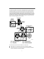
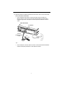
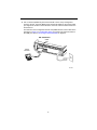
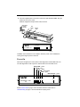
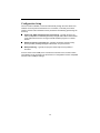
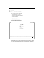
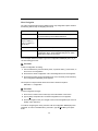
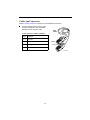
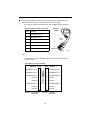
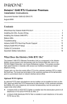
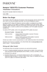
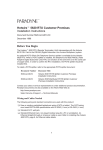
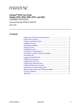
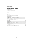
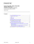
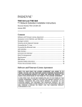
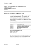
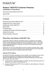
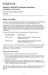
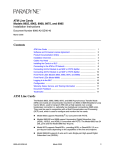
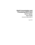
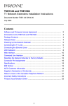
FrameSaver® DSL 9783 Router Installation Instructions Document Number 9783-A2-GN11-10 April 2001 Contents FrameSaver DSL 9783 Router Overview ...................................................... 1 Upgrading a Basic Unit to SLV ...................................................................... 3 Product Documentation Online ..................................................................... 3 Package Checklist ......................................................................................... 3 Wiring and Cables You May Need ................................................................ 4 Prior to Installing the Router ......................................................................... 5 Installing the Router ...................................................................................... 6 Status LEDs .................................................................................................. 10 Troubleshooting ............................................................................................. 11 Configuration Setup ...................................................................................... 12 Verifying that Self-Test Passed ..................................................................... 15 Using the Easy Install Feature ...................................................................... 15 Completing Setup From the NOC ................................................................. 16 Setting Up for In-Band Management ............................................................ 17 Provisioning the Router Interface .................................................................. 20 Cables and Connectors ................................................................................ 21 DSL Router Technical Specifications ............................................................ 24 Important Safety Instructions ........................................................................ 25 Government Requirements ........................................................................... 27 Warranty, Sales, Service, and Training Information ...................................... 28 FrameSaver DSL 9783 Router Overview The FrameSaver® DSL (Digital Subscriber Line) 9783 Router is a component in the FrameSaver system. This system allows you to perform end-to-end service level management (SLM) across a hybrid FrameSaver DSL/ATM/Frame Relay network. Service providers can isolate and correct problems remotely from their NOC (Network Operations Center). 1 The router has an SDSL front end and is a manageable frame relay aware endpoint. It operates as a bridge or an IP router that connects a DSL link to an Ethernet network. The FrameSaver DSL 9783 Router is used for data only and provides corporate LAN access over traditional twisted-pair copper telephone wiring. Copper pairs run from the central office (CO) to the customer premises (CP) to create the local loop. The local loop terminates on the customer premises at the demarcation point in a punchdown block or network interface device (NID). A typical example of using the FrameSaver DSL 9783 Router in a network configuration is shown below. Central Office Customer Premises– Remote Site POWER 48V NEG 48V RTN BEFORE REMOVING OR LAN DISCONNECTED AT THE SOURCE INSTALLING THIS PWR ENTRY MODULE 48V RTN POWER ENTRY MODULE LEFT UNIT: LINE A RIGHT UNIT: LINE B WARNING! POWER MUST BE POWER ENTRY MODULE LEFT UNIT: LINE A RIGHT UNIT: LINE B 48V NEG A CLOCK SERIAL AC A MCC ALARM 2 4 6 8 B SERIAL ALARM CLOCK SMCM 1 3 5 7 ALARMS B Fan Major Minor LAN/WAN SLOT A 10 12 14 16 18 11 13 15 17 Aggregation Switch (Optional) WARNING! POWER MUST BE BEFORE REMOVING OR DISCONNECTED AT THE SOURCE INSTALLING THIS PWR ENTRY MODULE 9 B POWER DSL A ALARMS B Fan Major Minor 48V NEG 48V RTN BEFORE REMOVING OR DISCONNECTED AT THE SOURCE INSTALLING THIS PWR ENTRY MODULE 48V RTN POWER ENTRY MODULE LEFT UNIT: LINE A RIGHT UNIT: LINE B WARNING! POWER MUST BE POWER ENTRY MODULE LEFT UNIT: LINE A RIGHT UNIT: LINE B 48V NEG FrameSaver Copper Loop DSL 9783 Hotwire Bridge/Router GranDSLAMs Endpoint CLOCK SERIAL AC A MCC ALARM 2 4 6 8 B SERIAL ALARM CLOCK SMCM 1 3 5 7 LAN/WAN SLOT A 10 12 14 16 18 11 13 15 17 WARNING! POWER MUST BE BEFORE REMOVING OR DISCONNECTED AT THE SOURCE INSTALLING THIS PWR ENTRY MODULE 9 B DSL Access Network Customer Premises– HQ Site ATM Services LAN FrameSaver Endpoint Router ATM NNI(s) ATM Switches ATM Switches FR Network FR Switches FR/ATM IWF TDM Access Network Frame Relay NSP's Network ATM – Asynchronous Transfer Mode DSL – Digital Subscriber Line FR – Frame Relay HQ – Headquarters 00-16915a IWF – Interworking Function LAN – Local Area Network NSP – Network Service Provider TDM – Time Division Multiplexer The FrameSaver DSL 9783 Router is available in two feature sets: Basic Feature Set 1 provides basic frame relay and diagnostic capability. Advanced SLV (Service Level Verification) Feature Set 2 provides basic features, plus SLV management and reporting capability. 2 Refer to About FrameSaver DSL Devices in the User’s Guide for a list of FrameSaver DSL 9783 features, and the capabilities provided by each feature set. Upgrading a Basic Unit to SLV A basic FrameSaver DSL 9783 Router can be upgraded to full SLV capability at any time by ordering a FrameSaver SLV Activation Certificate. A certificate can be ordered for a single 9783 router, or for many 9783 routers. The OpenLane® SLM system, Release 5.3 or later, is required to schedule the activation of SLV features, and to manage the certificate activations included in the certificate. To upgrade a basic 9783 router to full SLV capability, order the FrameSaver SLV Activation Certificate (Feature No. 9783-C1-220), providing the model to be activated (i.e., 9783-Rtr), your OpenLane SLM system license key number, the number of 9783 router activations to be included on the certificate. To learn more about activating SLV capability, refer to the FrameSaver SLV Activation Instructions (Document No. 9000-A2-GK43), or contact your sales representative. Product Documentation Online Complete documentation for this product is available at www.paradyne.com. Select Library → Technical Manuals → FrameSaver Frame Relay Devices. Select the following document: 9783-A2-GB20 FrameSaver DSL 9783 User’s Guide To order a paper copy of a Paradyne document: Within the U.S.A., call 1-800-PARADYNE (1-800-727-2396) Outside the U.S.A., call 1-727-530-8623 Package Checklist In addition to these instructions, verify that your package contains the following: ❑ FrameSaver DSL 9783 Router ❑ Power cord with power transformer ❑ Tie wrap for power cord strain relief ❑ DSL network access cable with 8-pin connectors – U.S. models only ❑ Ferrite choke – International models only ❑ FrameSaver DSL 9783 Router Quick Reference (Document No. 9783-A2-GL11) Be sure to register your warranty at www.paradyne.com/warranty. 3 Wiring and Cables You May Need The following wiring and cables are used with this product, which uses standard interface connectors: ❑ Standard connectors: An 8-pin modular (similar to RJ48C) or 6-pin modular (similar to RJ11) wall jack for the DSL network connection. ❑ DSL wiring: Unshielded twisted-pair wiring (CAT3, or better). The CAT3 wiring must meet EIA/TIA-568 specifications with 24 AWG (.5 mm) or 26 AWG (.4 mm). ❑ Ethernet wiring: Shielded twisted-pair wiring (CAT5, or better). The CAT5 wiring must meet EIA/TIA-568 specifications with 24 AWG (.5 mm) or 26 AWG (.4 mm). For standard cables, refer to Cables and Connectors on page 21 for pin numbers. For Paradyne cables, contact your sales representative to order them. Interface Connection COM port to a PC or asynchronous terminal Cables Feature Number DB25-to-DB25: Standard EIA-232 straight-through cable — DB25-to-DB9: DB25-to-8-pin modular adapter 3100-F1-920 8-pin modular-to-DB9 cable (14 feet – 4.3 m) 3100-F2-550 For connection to a PC NIC: ETHERNET port to a NIC on a PC Standard Ethernet crossover cable or an Ethernet hub For connection to an Ethernet Hub: Standard Ethernet straight-through cable NETwork to the DSL wall jack — — Standard straight-through DSL network cable with 8-pin modular connectors – similar to an RJ48C-toRJ48C cable (20 feet – 6.1 m). Cable supplied for use in the U.S. 3100-F1-500 Standard DSL network cable with 6-pin connectors – similar to an RJ11 cable — 4 Prior to Installing the Router These Installation Instructions assume that the virtual circuits at the DSLAM have already been configured. Provisioning of these circuits can be simplified by using the OpenLane SLM (Service Level Management) system, as indicated in Provisioning Data Circuits in OpenLane. Provisioning Data Circuits in OpenLane Use the OpenLane SLM system’s Provision Circuit screen to add new circuits that start at the FrameSaver DSL endpoint and traverse the SCM and ATM line card in the Hotwire GranDSLAM, and the default VC sets (from 1 to 4). A group of 250 VCs can be allocated to each line card, which can be assigned to any port on the card. These custom connections carry the frame relay traffic. Note that before the custom cross-connects are configured, the Maximum VCI number for the uplink VP to be used by these custom connections must be specified on the Max VCI per VPI screen, and the apply changes executed. For ATM line cards, custom connections can be used to expand the number of VCs connected to the card. Each of the 250 VCs can be cross-connected from any VC on the uplink to any port on the line card. The following information is collected by the Provision Circuit process: Uplink VPI/VCI Slot number and Port number of the DSL connection Traffic Profile DSL link VPI/VCI Frame relay DLCI (provided by NSP) Frame relay CIR, Be, Bc (provided by NSP) A Circuit ID is then applied to the newly defined circuit, and stored in both the router and the OpenLane SLM system. 5 Installing the Router Place the FrameSaver DSL 9783 Router on a flat surface, with clearance for the rear connectors. Procedure 1. Use the supplied 8-pin DSL network cable (for use in the U.S.), or a 6-pin DSL network cable (using connectors similar to RJ11), as applicable, for the DSL connection. Insert one end of the cable into the jack labeled NET on the router. Insert the other end into the wall jack for DSL data communications. DSL 9783 Router NET POW ER COM ETHE RNET DSL Network NET 00-16878 For domestic models, go to Step 3 on page 7. 2. For certain international models, a ferrite choke has been provided. Place the ferrite choke on the network cable, as close as possible to the rear panel. NET NET Close the two halves around the cable and snap the latch shut. DSL Network Ferrite Choke 01-16944 6 3. Use an 8-pin Ethernet cable for the Ethernet connection. Insert one end of the cable into the jack labeled ETHERNET. — Use a straight-through cable to connect the other end of the cable to an Ethernet hub. Do not connect to the hub’s optional Uplink connection with a straight-through cable; the Uplink connection requires an Ethernet crossover cable. DSL 9783 Router ETHERNET POW ER COM ETHE RNET NET Ethernet Straight-Through Cable Hub 00-16879 – or – — Use an Ethernet crossover cable to connect to a PC with an Ethernet Network Interface Card (NIC) installed or a hub’s Uplink connection. 7 4. Use a VT100-compatible asynchronous terminal or PC to set up management access to the unit. Insert the DB25 end of the EIA-232 cable into the router’s COM port. Tighten the screws on each side of the connector. Insert the other end into the terminal or PC. The terminal or PC’s configuration must be compatible with the router’s. Refer to the procedure on page 13 of Configuration Setup. If connecting an external modem to the COM port, refer to Connecting an External Modem on page 23. DSL 9783 Router COM Port POW ER COM ETHE RNET VT100 Terminal NET 00-16876 8 5. Insert the supplied power cord’s round end into the jack labeled POWER. Plug the transformer into an AC outlet. Install the supplied tie wrap for strain relief, as shown. Grounded Power Outlet Tie Wrap Power Jack POW ER COM ETHE RNET NET OOK K AATT MM DDS SLL OO KK AALL MM TTEE SSTT 9783-C 9783 ROUTER R R DSL FrameSaver ®® SLV TM SDSL System Port Port Network 01-16877-01 Installation of the hardware is now complete. When the power cord is installed, the router goes through a power-on self-test. Power-On When power is applied, the router performs self-diagnostics and the PWR LED is on. The self-diagnostics include a power-on self-test where all of the LEDs are on. System OK – green Alarm – red Test – yellow ATM – green/yellow DSL – green Ethernet Port – green O K AT M D SL TE ST O K AL M 9783 ROUTER R DSL FrameSaver ® SLV SDSL System Network Port 01-16857-01 Refer to Status LEDs on page 10 for information about the LEDs. Refer to Troubleshooting on page 11 for LED indications requiring action. 9 Status LEDs After a successful self-test, the LEDs should appear as indicated in BOLD in the Condition column below. LED Condition Status System LEDs OK ON The router has power. ALM ON An alarm condition exists. OFF No alarms have been detected by the router. ON The router is performing the power-on self-test, or a test initiated by the service provider is currently active. OFF No tests are active. TEST Network LEDs ATM DSL ON – Green ATM mode is active and cell delineation is in sync. ON – Yellow ATM mode is active and there is loss of cell delineation. Blinking The router is in start-up or is retraining. The LED blinks on and off about five times per second. ON The DSL link is ready to transmit and receive data. OFF No DSL link has been established, or the link is down. ON The Ethernet port is transmitting and receiving data. OFF Self-diagnostics have not been completed successfully. Port LED OK 10 Troubleshooting LED Symptom Action All LEDs are on. If the LEDs remain on for more than ten minutes, the router is not functional. Unplug the router and reapply power. If the ALM LED is still on, contact the service provider. ALM LED only remains on. The power-on self-test may have failed. Unplug the router and reapply power. If the alarm LED is still on, contact the service provider. ALM and TEST LEDs are blinking. Firmware download may be in progress. If firmware download is not in progress or the LEDs continue blinking for more than ten minutes, contact the service provider. Do not unplug the unit, unless instructed to do so by the service provider. ATM Yellow LED remains on. There is loss of cell delineation (OCD) due to line impairments. Contact the service provider. DSL LED is off. Verify that the DSL cable is securely installed on both ends. Unplug the unit and reapply power. If the problem continues, contact the service provider. DSL LED continues blinking after the power-on self-test has completed. The router is attempting to establish the DSL link, or adjusting the DSL line rate due to line conditions. If the blinking continues for more than ten minutes, contact the service provider. DSL LED is on, but no data is being transmitted. The DSL link has been established, but there is no data transmission. Verify the Ethernet connection. If the problem persists, contact the service provider. DSL and Port LEDs are on, but no data is being transmitted. DSL and Ethernet links have been established, but there is no data transmission. If the problem continues, contact the service provider. Port LED is off. Verify that the Ethernet cable is securely installed at both ends, and at least one PC is connected and powered on. Verify that the correct Ethernet straight-through or crossover cable is installed. Refer to Step 3 on page 7. System OK LED is off. Check that the power cord is securely installed on both ends. If no LEDs are on, the power supply may be defective. Test the outlet to verify power. If the outlet has power and the problem persists, contact your service representative. If other LEDs are on, the OK LED may be burned out. Unplug the unit and reapply power, and watch all LEDs as the router performs its power-on self-test. If the OK LED is functioning, call your service representative. TEST LED is on. A test initiated by the service provider may be active. Wait ten minutes. If the LED does not go off, contact the service provider. 11 Configuration Setup Once the router is installed, it can be accessed locally through the menu-driven user interface via an asynchronous terminal or PC connection, or remotely via a Telnet session, and the router’s interfaces can be provisioned. The following provisioning can be set up: Frame relay, ATM, and physical layer provisioning – Typically set up by the CLEC (Competitive Local Exchange Carrier) using the menu-driven user interface via an ASCII terminal or PC running a terminal emulation program, or a Telnet session. Router provisioning, using the CLI – Typically accessed by the frame relay service provider providing managed router service, or by the end user. SLM provisioning – Typically set up by the frame relay service provider or the CLEC. As soon as the router’s COM port is connected to a terminal or PC, the menu-driven user interface can be accessed. The terminal or PC’s configuration must be compatible with the router’s COM port settings. 12 Procedure To access the menu-driven user interface: 1. Verify the terminal or PC’s configuration: — Data Rate is set to 19.2 kbps. — Character Length is set to 8 data bits. — Parity is set to None. — Stop Bits is set to 1. — Flow Control is set to None. 2. Press Enter to display the Main Menu. main Device Name: Node A 9783-RtrSLV 2/26/2001 00:02 MAIN MENU Status Test Configuration Control Easy Install ----------------------------------------------------------------------------Ctrl-a to access these functions, Shift-r to access the Router's CLI. Exit If the Main Menu does not appear, recheck the terminal or PC’s settings, or press Enter again. Refer to Troubleshooting in the User’s Guide for other explanations. 13 Menu Navigation The router should operate using the default (factory-set) configuration options. Refer to the following table for help in navigating the menus. Press the . . . To . . . Esc key Go back one screen or menu level. For a visual display of the menu hierarchy, see the Quick Reference. Tab key, and Up (↑), Down (↓ ), Left (←), Right (→) Arrow keys Move the cursor from one menu item to the next. Enter or Return key Complete the menu or option selection. Spacebar Display the next available setting when changing a configuration option. All the available settings for an option appear at the bottom of the screen. As an example, follow these steps to go to the Configuration Edit/Display menu so you can start setting up the unit. Procedure To load a configuration for editing: 1. From the Main Menu, press the Tab key twice, or press the down (↓) arrow twice, so the cursor is on Configuration. 2. Press Enter to select Configuration. The Load Configuration From menu appears. 3. Press Enter to select Current Configuration (the cursor is already on this selection). The Configuration Edit/Display menu appears. This sequence of steps would be shown as the menu selection sequence: Main Menu → Configuration Procedure To save configuration changes: 1. Press Ctrl-a to switch to the function keys area at the bottom of the screen. 2. Type s (Save) and press Enter. The Save Configuration To menu appears. 3. Press Enter again to save your changes to the Current Configuration (the cursor is already on this selection). To continue configuring the router, press Esc until the Configuration Edit/Display menu reappears. To return to the Main Menu, press Ctrl-a, type m (MainMenu), and press Enter. 14 Verifying that Self-Test Passed To verify that the unit passed its self-test, go to the System and Test Status screen. Main Menu → Status → System and Test Status The results of the self-test appear directly under the screen title. If any failure messages appear, reset the unit by disconnecting, then reconnecting the power cord. The unit will perform the self-test again. If the failure reappears, call your service representative for assistance. Using the Easy Install Feature An Easy Install screen is provided for custom configurations, but you are not required to use it for normal installation. You can configure the router by making selections from the Configuration Edit/Display menu. Procedure 1. Select the Easy Install feature. Main Menu → Easy Install Easy Install Screen Example main/easy_install Device Name: Node A 9783-RtrSLV 2/26/2001 00:01 EASY INSTALL DSLAM Type: Paradyne Node IP Address: Node Subnet Mask: TS Access: VPI,VCI 000.000.000.000 000.000.000.000 0,35 Clear Clear Create a Dedicated Network Management Link Ethernet Management Options Screen Network 1 DSL Line Rate (Kbps) Network 1 FRF.8 Encapsulation Mod AutoRate Transparent ----------------------------------------------------------------------------Ctrl-a to access these functions, ESC for previous menu MainMenu Exit Save 15 2. If the router will not be connected to a Paradyne DSLAM, change the DSLAM Type. Other selections are Alcatel (NewBridge), PairGain, and Nokia. 3. Enter the Node IP Address and Subnet Mask. 4. Specify TS Access if a Troubleshooting (TS) DLCI or Virtual Circuit (VC) is being set up for remote access by the service provider. The default is 0,35. 5. Select Create a Dedicated Network Management Link to set up for permanent remote access by the NOC. Enter a DLCI, VPI, and VCI at the resulting prompts. 6. Select the Ethernet Management Options Screen to go directly to the Ethernet Management Options screen. The interface (Status) is already enabled. — Enter the IP Address (e.g., 10.101.51.253) and Subnet Mask (e.g., 255.255.255.0) for the Ethernet interface. — Enter the Default Gateway Address (the IP Address that will be used for packets without a specified route). — Press the Esc key to return to the Easy Install screen. 7. Change Network 1 DSL Line Rate (Kbps), if desired. The default is AutoRate. If a Paradyne DSLAM is used, the default setting is AutoRate. For non-Paradyne DSLAMs, the AutoRate setting is not valid and the default rate is 784 kbps. 8. Change Network 1 FRF.8 Encapsulation Mode, if desired. The default is Transparent (data is forwarded without translation), which supports both frame relay and ATM PVCs, and FrameSaver proprietary multiplexing. 9. Save the configuration and return to the Configuration Edit/Display menu. Completing Setup From the NOC Procedure 1. Access the router on the TS Management Link that was set up at the remote site in Step 5 of Using the Easy Install Feature. 2. Ping the router five times within five seconds. The router automatically provisions the TS Access VC and accepts the destination IP address of the Ping as its temporary IP address, which is used on the management VC interface. 3. If necessary, open a Telnet session and configure any specific configuration options that require input or changes from default settings. Create all customer VCs, including internal DLCIs and VPI/VCIs on the DSL interface, and cross-connect the DLCIs to the VCCs. 16 Configuring SNMP Trap Managers and Traps Procedure To enter SNMP managers and configure traps: 1. Select SNMP Traps. Main Menu → Configuration → Management and Communication → SNMP Traps 2. Configure the following: — Enable SNMP Traps. — Identify the total Number of Trap Managers. — Specify the IP address for each NMS Trap Manager to which traps will be sent. — Specify the Initial Route Destination for each Trap Manager. The default is AutoRoute. — Select or disable trap categories, as needed. 3. Save the configuration. Setting Up for In-Band Management If FRF.8 Encapsulation Mode is set to Translational, remote management of the router can still be accomplished in-band, as indicated in the following procedure. The following procedure assumes that the router’s Ethernet interface has already been assigned an IP address that is in the same subnet as the management IP address entered in Step 6 on page 16 of Using the Easy Install Feature, and that the router is not configured for bridging only. Refer to Configuring the FrameSaver DSL Router ; CLI Commands, Codes, and Designations, and Command Line Summaries and Shortcuts in the User’s Guide for additional information. 17 Procedure 1. Create a DLCI on the router virtual port. Configuration → Virtual Router Ports → DLCI Records Assign the DLCI number that will be used for management on Serial port 0 (Rtr-S0 – e.g., DLCI 900). 2. Create a management PVC using the DLCI just configured on Serial port 0 to connect the management link to the router. Configuration → Management and Communication → Management PVCs Using the DLCI 900 example, make the following connection: — Select Name: Mgmt900 — Intf IP Address: Special, and add the IP address for the Ethernet interface in Step 6 on page 16 of Using the Easy Install Feature. — Intf Subnet Mask: Special, and add the Subnet Mask for the Ethernet interface in Step 6 on page 16 of Using the Easy Install Feature. — Set DE: Leave at the default, Disable. — Primary Link: Select Rtr-S0. — Primary DLCI: Select 900. 3. Return to the Main Menu and press Shift-r to access the router’s CLI. 4. From the CLI, enable password and show the router’s configuration. en show config A list of the router’s configuration is shown, most of the configuration already completed using the default values. interface serial 0.900 ip unnumbered frame-relay interface-dlci 900 no bridge-group 1 exit 5. Add the route to the routing table. config t ip route 10.101.51.253 255.255.255.255 Serial 0.900 save exit 6. Ping the Ethernet management interface to verify that the router can be reached. ping 10.101.51.253 exit The router is now set up for in-band management. 18 Verifying the End-to-End Management Path After installation of a remote router, run an ATM Ping test from the Hotwire® GranDSLAM. Procedure To Ping the router: 1. From the Hotwire ATM Line Card’s Main Menu, select the ATM Ping test. Diagnostics → ATM Ping (D-C) 2. Enter a VPI of 0 and a VCI of 35. 3. Select a Direction of Endpoint, then Start. 4. If the test is successful, select a Direction of Network, then Start. If both tests are successful, the VC has been tested from end to end. Checking That Data is Being Received Procedure To verify that data is being received: 1. From the router’s Main Menu, select frame relay performance statistics. Main Menu → Status → Performance Statistics → Frame Relay 2. Repeatedly Refresh the screen to: — Verify that the counts for Frames Received and Characters Received under the Frame Relay Link statistics are increasing. — Verify that there are no errors under Frame Relay Errors. If data is not being received or you are receiving errors, check your cable connections and replace or repair a damaged cable. 3. Return to the Status menu. 19 Checking PVC Connections Check PVC connections to verify that all PVCs, including management PVCs, are configured and active. Procedure To verify PVCs: 1. Select PVC Connection Status from the Status menu. The PVC Connection Status screen shows all PVC connections, the interface source and DLCI number of the incoming data linked to the interface, and DLCI number for the outgoing data. You can also see whether the PVC is active. 2. Verify that each PVC is active. — If active, the router should be passing data. — If not active, no data traffic can be carried by the PVC. If the PVC is configured correctly, the circuit may be down. Provisioning the Router Interface The FrameSaver DSL 9783 Router defaults to bridge mode. Routing without bridging, and simultaneous routing and bridging, are also options. Use the bridge command from the router’s CLI to configure the bridge and routing attributes. Also, enter an Ethernet IP address and a DHCP IP address. Refer to the Quick Reference for a summary of configuration options, CLI commands, and default settings. 20 Cables and Connectors Refer to Installing the Router on page 6 for cable installation information. The DSL network interface uses an 8-pin, un-keyed modular plug. Use a standard twisted-pair CAT3, or better, cable. 8-Pin Connector (Similar to RJ48C) DSL Cable Pin # Function 1–3 Not used 4 DSL Ring 5 DSL Tip 6–8 Not used Pin #8 Pin #1 01-16887-01 21 The Ethernet interface connector uses an 8-pin, non-keyed modular plug. Use shielded twisted-pair CAT5, or better, cables. See Step 3 on page 7. — To connect the router to an Ethernet hub, use a straight-through connection. 8-Pin Straight-Through Connections Pin # Function 1 10/100BaseT TX D+ 2 10/100BaseT TX D– 3 10/100BaseT RX D+ 4&5 6 7&8 Ethernet Cable 8-Pin Plug Not used 10/100BaseT RX D– Not used Pin #8 Pin #1 98-16055a – or – — To connect the router to a PC with an Ethernet NIC card, use an Ethernet crossover cable. 8-Pin Ethernet Crossover Cable Function Pin # Pin # Function 10/100BaseT TX D+ 1 1 10/100BaseT TX D+ 10/100BaseT TX D– 2 2 10/100BaseT TX D– 10/100BaseT RX D+ 3 3 10/100BaseT RX D+ Not Used 4 4 Not Used Not Used 5 5 Not Used 10/100BaseT RX D– 6 6 10/100BaseT RX D– Not Used 7 7 Not Used Not Used 8 8 Not Used Pin #1/2 = Orange/White Twisted Pair Pin #3/6 = Blue/White Twisted Pair 22 99-16518 The communication (COM) port connector uses a 25-position, EIA-232-C connector. Pin # Signal Direction 1 Shield (GND) — 2 DCE Transmit Data (TXD) From DTE (In) 3 DCE Receive Data (RXD) To DTE (Out) 4 DCE Request To Send (RTS) From DTE (In) 5* DCE Clear To Send (CTS) To DTE (Out) 6* DCE Data Set Ready (DSR) To DTE (Out) 7 Signal Ground (GND) — 8* DCE Carrier Detect (CD) To DTE (Out) 9–19 Not used — 20 DCE Data Terminal Ready (DTR) From DTE (In) 21–25 Not used — * Pins 5, 6, and 8 are tied together. Connecting an External Modem A standard crossover cable can be used to connect the COM port to an external modem. Configure the external modem to be compatible with the FrameSaver unit. Refer to Connectors, Cables, and Pin Assignments in the User’s Guide for standard crossover cable external modem pin assignments and AT commands to configure the modem and enable auto-answer. 23 DSL Router Technical Specifications Item Specification* Approvals FCC Part 15 Class A digital device Safety Certifications Refer to equipment’s label for approvals on product Physical Environment Operating temperature 32°F to 122°F (0°C to 50°C) Storage temperature –4°F to 158°F (–20°C to 70°C) Relative humidity 5% to 85% (noncondensing) Shock and vibration Withstands normal shipping and handling Power Consumption and Dissipation 4.5 watts, 60 Hz ±3, 0.135 A at 120 VAC ±12 Result: 15.4 Btu per hour Height x Width x Depth 2.1" x 6.2" x 8.7" (5.3 cm x 15.7 cm x 22.1 cm) Weight 1.38 lbs. (0.62 kg) COM Port 25-position (DB25) connector Standard EIA-232, V.24 (ISO 2110) Data rates 9.6, 14.4, 19.2, 28.8, 38.4, 57.6, and 115.2 kbps DSL Network (NET) 8-position modular unkeyed jack (similar to RJ45) Line Code 2B1Q Service SDSL Data rates 144–2320 kbps Ethernet Port 8-position modular unkeyed jack Standard ANSI/IEEE Standard 802.3, Ethernet Version 2 Data rates 10/100 BaseT (auto-sensing 10/100 Mbps rates) * Technical Specifications are subject to change without notification. 24 ! Important Safety Instructions 1. Read and follow all warning notices and instructions marked on the product or included in the manual. 2. Slots and openings in the cabinet are provided for ventilation. To ensure reliable operation of the product and to protect it from overheating, these slots and openings must not be blocked or covered. 3. Do not allow anything to rest on the power cord and do not locate the product where persons will walk on the power cord. 4. Do not attempt to service this product yourself, as opening or removing covers may expose you to dangerous high voltage points or other risks. Refer all servicing to qualified service personnel. 5. General purpose cables are used with this product for connection to the network. Special cables, which may be required by the regulatory inspection authority for the installation site, are the responsibility of the customer. Use a UL Listed, CSA certified, minimum No. 24 AWG line cord for connection to the Digital Subscriber Line (DSL) network. 6. When installed in the final configuration, the product must comply with the applicable Safety Standards and regulatory requirements of the country in which it is installed. If necessary, consult with the appropriate regulatory agencies and inspection authorities to ensure compliance. 7. A rare phenomenon can create a voltage potential between the earth grounds of two or more buildings. If products installed in separate buildings are interconnected, the voltage potential may cause a hazardous condition. Consult a qualified electrical consultant to determine whether or not this phenomenon exists and, if necessary, implement corrective action prior to interconnecting the products. 8. Input power to this product must be provided by one of the following: (1) a UL Listed/CSA certified power source with a Class 2 or Limited Power Source (LPS) output for use in North America, or (2) a certified transformer, with a Safety Extra Low Voltage (SELV) output having a maximum 240 VA available, for use in the country of installation. 9. In addition, if the equipment is to be used with telecommunications circuits, take the following precautions: — Never install telephone wiring during a lightning storm. — Never install telephone jacks in wet locations unless the jack is specifically designed for wet locations. — Never touch uninsulated telephone wires or terminals unless the telephone line has been disconnected at the network interface. — Use caution when installing or modifying telephone lines. — Avoid using a telephone (other than a cordless type) during an electrical storm. There may be a remote risk of electric shock from lightning. — Do not use the telephone to report a gas leak in the vicinity of the leak. 25 CE Marking When the product is marked with the CE mark on the equipment label, this demonstrates full compliance with the following European Directives: Directive 73/23/EEC – Council Directive of 19 February 1973 on the harmonization of the laws of the member states relating to electrical equipment designed for use within states relating to electrical equipment designed for use within certain voltage limits, as amended by Directive 93/68/EEC. Directive 89/336/EEC – Council Directive of 3 May 1989 on the approximation of the laws of the member states relating to Electro-Magnetic Compatibility (EMC), as amended by Directive 93/68/EEC. EMI Notices ! UNITED STATES – EMI NOTICE: This equipment has been tested and found to comply with the limits for a Class A digital device, pursuant to Part 15 of the FCC rules. These limits are designed to provide reasonable protection against harmful interference when the equipment is operated in a commercial environment. This equipment generates, uses, and can radiate radio frequency energy and, if not installed and used in accordance with the instruction manual, may cause harmful interference to radio communications. Operation of this equipment in a residential area is likely to cause harmful interference in which case the user will be required to correct the interference at his own expense. The authority to operate this equipment is conditioned by the requirements that no modifications will be made to the equipment unless the changes or modifications are expressly approved by Paradyne Corporation. ! CANADA – EMI NOTICE: This Class A digital apparatus meets all requirements of the Canadian interference-causing equipment regulations. Cet appareil numérique de la classe A respecte toutes les exigences du règlement sur le matérial brouilleur du Canada. 26 Government Requirements Certain governments require that instructions pertaining to connection to the telephone network be included in the installation and operation manual. Specific instructions are listed in the following sections. Notice to Users of the Canadian Telephone Network The Industry Canada label identifies certified equipment. This certification means that the equipment meets telecommunications network protective, operational and safety requirements as prescribed in the appropriate Terminal Equipment Technical Requirements document(s). The Department does not guarantee the equipment will operate to the user’s satisfaction. Before installing this equipment, users should ensure that it is permissible to be connected to the facilities of the local telecommunications company. The equipment must also be installed using an acceptable method of connection. The customer should be aware that compliance with the above conditions may not prevent degradation of service in some situations. Repairs to certified equipment should be coordinated by a representative designated by the supplier. Any repairs or alterations made by the user to this equipment, or equipment malfunctions, may give the telecommunications company cause to request to disconnect the equipment. Users should ensure for their own protection that the electrical ground connections of the power utility, telephone lines and internal metallic water pipe system, if present, are connected together. This precaution may be particularly important in rural areas. CAUTION: Users should not attempt to make such connections themselves, but should contact the appropriate electric inspection authority, or electrician, as appropriate. The Ringer Equivalence Number (REN) assigned to each terminal device provides an indication of the maximum number of terminals allowed to be connected to a telephone interface. The termination on an interface may consist of any combination of devices subject only to the requirement that the sum of the Ringer Equivalence Numbers of all the devices does not exceed 5. If your equipment is in need of repair, refer to Warranty, Sales, Service, and Training Information on page 28. 27 Warranty, Sales, Service, and Training Information Contact your local sales representative, service representative, or distributor directly for any help needed. For additional information concerning warranty, sales, service, repair, installation, documentation, training, distributor locations, or Paradyne worldwide office locations, use one of the following methods: Internet: Visit the Paradyne World Wide Web site at www.paradyne.com. (Be sure to register your warranty at www.paradyne.com/warranty.) Telephone: Call our automated system to receive current information by fax or to speak with a company representative. — Within the U.S.A., call 1-800-870-2221 — Outside the U.S.A., call 1-727-530-2340 Document Feedback We welcome your comments and suggestions about this document. Please mail them to Technical Publications, Paradyne Corporation, 8545 126th Ave. N., Largo, FL 33773, or send e-mail to [email protected]. Include the number and title of this document in your correspondence. Please include your name and phone number if you are willing to provide additional clarification. Trademarks FrameSaver, Hotwire, and OpenLane are registered trademarks of Paradyne Corporation. All other products and services mentioned are the trademarks, service marks, registered trademarks, or registered service marks of their respective owners. " *9783-A2-GN11-10* Copyright © 2001 Paradyne Corporation. Printed in U.S.A. 28