1
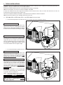
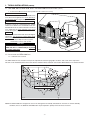
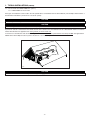
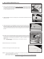
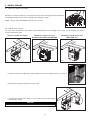
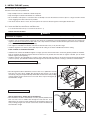
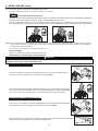
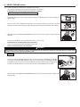
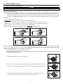
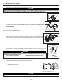
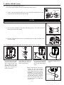
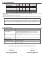
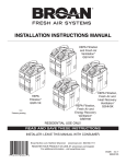
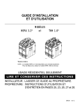
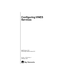
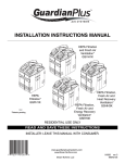
INSTALLATION INSTRUCTIONS
AND USER MANUAL
MODELS
HRV 2600*
HR 2.6*
HEPA 3100*
HF 3.1*
HEPA 4100*
VB0064
NOTES: 1. HRV 2600* model is available in Canada only.
2. HEPA 4100* model is available in United States only.
*Patents pending
RESIDENTIAL USE ONLY
READ AND SAVE THESE INSTRUCTIONS
INSTALLER: LEAVE THIS MANUAL WITH THE HOMEOWNER.
HOMEOWNER: USE AND CARE INFORMATION ON PAGES 18 TO 21.
04313
rev. 11
ABOUT THIS MANUAL
First, we want to congratulate you on your purchase of this excellent unit which will allow you and your family to enjoy clean and healthy
air throughout your home for years to come!
Because of the large amount of models covered by this publication, the illustrations are typical ones. Some details of your unit may be
slightly different than the ones shown.
Please take note that this manual uses the following symbols to emphasize particular information:
! WARNING
Identifies an instruction which, if not followed, might cause serious personal injuries including possibility of death.
CAUTION
Denotes an instruction which, if not followed, may severely damage the unit and/or its components.
NOTE: Indicates supplementary information needed to fully complete an instruction.
We welcome any suggestions you may have concerning this manual and/or the unit, and we would appreciate hearing your comments
on ways to better serve you. Please contact us by phone at one of the following numbers:
IN CANADA
IN U.S.A.
Exclusively for HR and HF Models:
Broan-NuTone Canada Inc.
1-866-737-7770
Exclusively for HR and HF Models:
Broan LLC
1-800-637-1453
Exclusively for HRV and HEPA Models:
Venmar Ventilation inc.
1-800-567-3855
Exclusively for HRV and HEPA Models:
Venmar Ventilation inc.
1-800-567-3855
ABOUT THESE UNITS
!
WARNING
TO REDUCE THE RISK OF FIRE, ELECTRIC SHOCK, OR INJURY TO PERSON(S) OBSERVE THE FOLLOWING:
1. This unit is intended for residential installation only.
2. Use this unit only in the manner intended by the manufacturer. If you have questions, contact the manufacturer at the address or
telephone number listed in the warranty.
3. Before replacing filters, servicing or cleaning unit, disconnect power cord from electrical outlet.
4. Installation must be done in accordance with all applicable codes and standards, including fire-rated construction codes and standards.
5. This unit is not designed to provide combustion and/or dilution air for fuel-burning appliances.
6. When cutting or drilling into wall or ceiling, do not damage electrical wiring and other hidden utilities.
7. Do not use this unit with any solid-state speed control device other than optional wall controls 40415 and 40425.
8. This unit must be grounded. The power supply cord has a 3-prong grounding plug for your personal safety. It must be plugged into a
mating 3-prong grounding receptacle, grounded in accordance with the national electrical code and local codes and ordinances. Do
not remove the ground prong. Do not use an extension cord.
9. Do not install in a cooking area or connect directly to any appliances.
10. Do not use to exhaust hazardous or explosive materials and vapors.
11. When performing installation, servicing or cleaning the unit, it is recommended to wear safety glasses and gloves.
12. When applicable local regulations comprise more restrictive installation and/or certification requirements, the aforementioned
requirements prevail on those of this document and the installer agrees to conform to these at his own expenses.
CAUTION
1.
2.
3.
4.
5.
To avoid prematurate clogged filters, turn OFF the unit during construction or renovation.
Please read specification label on product for further information and requirements.
Be sure to duct air outside – Do not intake/exhaust air into spaces within walls or ceiling or into attics, crawl spaces, or garage.
Intended for residential installation only in accordance with the requirements of NFPA 90B.
Do not run any air ducts directly above or closer than 2 ft (0.61 m) to any furnace or its supply plenum, boiler, or other heat producing
appliance. If a duct has to be connected to the furnace return plenum, it must be connected not closer than 9’ 10” (3 m) from this
plenum connection to the furnace.
6. The ductwork is intended to be installed in compliance with all local and national codes that are applicable.
-2-
TABLE OF CONTENTS
1. TYPICAL INSTALLATIONS . . . . . . . . . . . . . . . . . . . . . . . . . . . . . . . . . . . . . . . . . . . . . . . . . .4-6
1.1 HRV 2600, HR 2.6, HEPA 3100, HF 3.1 AND HEPA 4100 UNIT INSTALLATIONS . . . . . . . . . . . . . . . . . . 4
1.1.1 STAND ALONE . . . . . . . . . . . . . . . . . . . . . . . . . . . . . . . . . . . . . . . . . . . . . . . . . . . . . . . . . . . . . . . .4
1.1.2 CENTRAL DRAW POINT . . . . . . . . . . . . . . . . . . . . . . . . . . . . . . . . . . . . . . . . . . . . . . . . . . . . . . . . . .4
1.1.3 RETURN-TO-RETURN INSTALLATION . . . . . . . . . . . . . . . . . . . . . . . . . . . . . . . . . . . . . . . . . . . . . . . . .5
1.2 INSTALLATIONS FOR HEPA 4100 ONLY . . . . . . . . . . . . . . . . . . . . . . . . . . . . . . . . . . . . . . . . . . . . . . . . . . .5
1.2.1 GEOGRAPHICAL LOCATION . . . . . . . . . . . . . . . . . . . . . . . . . . . . . . . . . . . . . . . . . . . . . . . . . . . . . . .5
1.2.2 HEPA 4100 ATTIC INSTALLATION . . . . . . . . . . . . . . . . . . . . . . . . . . . . . . . . . . . . . . . . . . . . . . . . . .6
2. DIMENSIONS . . . . . . . . . . . . . . . . . . . . . . . . . . . . . . . . . . . . . . . . . . . . . . . . . . . . . . . . . . . .7
2.1 HRV 2600 AND HR 2.6 UNITS . . . . . . . . . . . . . . . . . . . . . . . . . . . . . . . . . . . . . . . . . . . . . . . . . . . . . . . 7
2.2 HEPA 3100, HF 3.1 AND HEPA 4100 UNITS . . . . . . . . . . . . . . . . . . . . . . . . . . . . . . . . . . . . . . . . . . . . .7
2.3 MOUNTING AND SERVICING CONSIDERATIONS . . . . . . . . . . . . . . . . . . . . . . . . . . . . . . . . . . . . . . . . . . . . . . .7
3. BEFORE STARTING . . . . . . . . . . . . . . . . . . . . . . . . . . . . . . . . . . . . . . . . . . . . . . . . . . . . . . . .8
3.1 INSPECT THE CONTENT OF THE BOX . . . . . . . . . . . . . . . . . . . . . . . . . . . . . . . . . . . . . . . . . . . . . . . . . . . .8
3.2 TOOLS, MATERIALS AND INSTALLATION KITS . . . . . . . . . . . . . . . . . . . . . . . . . . . . . . . . . . . . . . . . . . . . . . .8
3.3 LOCATING THE UNIT . . . . . . . . . . . . . . . . . . . . . . . . . . . . . . . . . . . . . . . . . . . . . . . . . . . . . . . . . . . . . . . .8
4 WALL CONTROL INSTALLATION . . . . . . . . . . . . . . . . . . . . . . . . . . . . . . . . . . . . . . . . . . . . .9-10
5 INSTALL THE UNIT . . . . . . . . . . . . . . . . . . . . . . . . . . . . . . . . . . . . . . . . . . . . . . . . . . . . .11-17
5.1 MOUNT THE PORTS ON THE UNIT . . . . . . . . . . . . . . . . . . . . . . . . . . . . . . . . . . . . . . . . . . . . . . . . . . . . .11
5.2 HOW TO HANG THE UNIT . . . . . . . . . . . . . . . . . . . . . . . . . . . . . . . . . . . . . . . . . . . . . . . . . . . . . . . . . . .11
5.3 PLANNING OF THE DUCTWORK . . . . . . . . . . . . . . . . . . . . . . . . . . . . . . . . . . . . . . . . . . . . . . . . . . . . . . . .12
5.4 INSTALLING NON-INSULATED DUCTS AND REGISTERS . . . . . . . . . . . . . . . . . . . . . . . . . . . . . . . . . . . . .12-14
5.4.1 STAND ALONE SYSTEM . . . . . . . . . . . . . . . . . . . . . . . . . . . . . . . . . . . . . . . . . . . . . . . . . . . . .12-13
5.4.2 CENTRAL DRAW POINT . . . . . . . . . . . . . . . . . . . . . . . . . . . . . . . . . . . . . . . . . . . . . . . . . . . . .13-14
5.4.3 RETURN-TO-RETURN . . . . . . . . . . . . . . . . . . . . . . . . . . . . . . . . . . . . . . . . . . . . . . . . . . . . . . . . . .14
5.5 INSTALLING INSULATED FLEXIBLE DUCTS . . . . . . . . . . . . . . . . . . . . . . . . . . . . . . . . . . . . . . . . . . . . . . .15-16
5.5.1 CONNECTION TO TANDEM® TRANSITION . . . . . . . . . . . . . . . . . . . . . . . . . . . . . . . . . . . . . . . . . . . . .15
5.5.2 CONNECTION TO THE 5” TO 6” OVAL PORTS OF THE UNIT . . . . . . . . . . . . . . . . . . . . . . . . . . . . . .15-16
5.6 INSTALLING DUAL EXTERIOR HOOD . . . . . . . . . . . . . . . . . . . . . . . . . . . . . . . . . . . . . . . . . . . . . . . . . .16-17
5.6.1 ASSEMBLING DUAL EXTERIOR HOOD . . . . . . . . . . . . . . . . . . . . . . . . . . . . . . . . . . . . . . . . . . . . . .16
5.6.2 LOCATING THE DUAL EXTERIOR HOOD . . . . . . . . . . . . . . . . . . . . . . . . . . . . . . . . . . . . . . . . . . . . .16
5.6.3 CONNECTING TANDEM® TRANSITION TO THE DUAL EXTERIOR HOOD . . . . . . . . . . . . . . . . . . . . .16-17
5.7 CONNECTING THE DRAIN . . . . . . . . . . . . . . . . . . . . . . . . . . . . . . . . . . . . . . . . . . . . . . . . . . . . . . . . . . .17
6 CONTROLS . . . . . . . . . . . . . . . . . . . . . . . . . . . . . . . . . . . . . . . . . . . . . . . . . . . . . . . . .18-19
6.1 MAIN SWITCH . . . . . . . . . . . . . . . . . . . . . . . . . . . . . . . . . . . . . . . . . . . . . . . . . . . . . . . . . . . . . . . . . . .18
6.2 40415 AND 40425 WALL CONTROLS DESCRIPTION . . . . . . . . . . . . . . . . . . . . . . . . . . . . . . . . . . . . . . . . .18
6.3 OPERATING 40415 / 40425 CONTROLS . . . . . . . . . . . . . . . . . . . . . . . . . . . . . . . . . . . . . . . . . . . . . . . . .18
6.4 WALL CONTROLS CONFIGURATION . . . . . . . . . . . . . . . . . . . . . . . . . . . . . . . . . . . . . . . . . . . . . . . . . . . . .19
7 MAINTENANCE . . . . . . . . . . . . . . . . . . . . . . . . . . . . . . . . . . . . . . . . . . . . . . . . . . . . . . .20-21
7.1 BIANNUAL MAINTENANCE . . . . . . . . . . . . . . . . . . . . . . . . . . . . . . . . . . . . . . . . . . . . . . . . . . . . . . . . .20-21
7.2 ANNUAL MAINTENANCE . . . . . . . . . . . . . . . . . . . . . . . . . . . . . . . . . . . . . . . . . . . . . . . . . . . . . . . . . . . . .21
8 PARTS ORDERING CHART . . . . . . . . . . . . . . . . . . . . . . . . . . . . . . . . . . . . . . . . . . . . . . . . . .22
9 TROUBLESHOOTING . . . . . . . . . . . . . . . . . . . . . . . . . . . . . . . . . . . . . . . . . . . . . . . . . . . . . .22
-3-
1. TYPICAL INSTALLATIONS
Installations may vary according to the model number and the position in which the unit is installed. Use the following illustrations as
guidelines to help you decide on how your unit will be installed.
All the units should be hung from the joists, and installed either vertically or horizontally.
NOTE: For more details, see Point 5.2 in Section 5 INSTALL THE UNIT.
In every case, bathroom fans and a range hood should be used to exhaust stale air. Also, for homes with more than one level, we
recommend one exhaust register at the highest level.
There are 3 installation methods: Stand Alone, Central Draw Point and Return-to-Return Installation.
NOTE: An electrical outlet has to be available within 3 feet of the unit.
1.1 HRV 2600, HR 2.6, HEPA 3100, HF 3.1
1.1.1 STAND ALONE (PRIMARILY
HRV 2600
AND
HR 2.6
AND
HEPA 4100 UNIT INSTALLATIONS
FOR HOMES WITH RADIANT HOT WATER OR ELECTRIC BASEBOARD HEATING.)
UNITS ONLY
Stale air coming from the register located at the
highest level of the house is exhausted to the outside.
Outside fresh air is filtered and supplied by the register
located in the lowest liveable level. See figure at right.
HEPA 3100, HF 3.1
AND
HEPA 4100
UNITS ONLY
A portion of stale air coming from the register located
at the highest level of the house is exhausted to the
outside and the rest is drawn to the unit. Outside
fresh air is blended with interior air and then filtered.
Fresh filtered air is supplied by the register located
in the lowest liveable level. See figure at right.
VH0039
1.1.2 CENTRAL DRAW POINT (CONNECTION TO
HRV 2600
AND
HR 2.6
A FORCED AIR SYSTEM)
UNITS ONLY
Stale air coming from the register located at the
highest level of the house is exhausted to the outside.
Outside fresh air is filtered and supplied to the return
(plenum) of the forced air unit. See figure at right.
HEPA 3100, HF 3.1
AND
HEPA 4100
UNITS ONLY
A portion of stale air coming from the register located
at the highest level of the house is exhausted to the
outside and the rest is drawn to the unit. Outside
fresh air is blended with interior air and then filtered.
This filtered air is supplied to the return (plenum) of
the forced air unit. See figure at right.
ALL UNITS:
For this type of installation, it is not essential that
the forced air system blower runs when the unit is
in operation, but we recommend it.
NOTE: Home with multiple forced air systems
should have 1 unit on each system.
CAUTION
Do not connect the unit (HRV 2600, HR 2.6,
HEPA 3100, HF 3.1 or HEPA 4100) to any forced
air system supply duct.
VH0040
-4-
1. TYPICAL INSTALLATIONS (CONT’D)
1.1 HRV 2600, HR 2.6, HEPA 3100, HF 3.1
AND
HEPA 4100 UNIT INSTALLATIONS (CONT’D)
1.1.3 RETURN-TO-RETURN INSTALLATION (CONNECTION TO
HRV 2600
AND
HR 2.6
A FORCED AIR SYSTEM)
UNITS ONLY
Stale air is exhausted to the outside. Outside fresh
air is filtered and supplied to the return (plenum) of
the forced air unit. See figure at right.
HEPA 3100, HF 3.1
AND
HEPA 4100
UNITS ONLY
A portion of stale air is exhausted to the outside
and the rest is drawn to the unit. Outside fresh air is
blended with interior air and then filtered. This filtered
air is supplied to the return (plenum) of the forced
air unit. See figure at right.
ALL UNITS:
To avoid cross-contamination and achieve the highest
efficiencies, the forced air system blower must
always be ON.
NOTE: Home with multiple forced air systems
should have 1 unit on each system.
CAUTION
Do not connect the unit (HRV 2600, HR 2.6,
HEPA 3100, HF 3.1 or HEPA 4100) to any forced
air system supply duct.
1.2 INSTALLATION
FOR
VH0043
HEPA 4100 ONLY
1.2.1 GEOGRAPHICAL LOCATION
The HEPA 4100 unit was created to meet specific requirements related to geographic locations. Take a look at the map below.
This unit can be installed anywhere in the USA, but the ventilation will be reduced in cold weather. HEPA filtration is not affected however.
HELENA
OLYMPIA
BISMARCK
ST. PAUL
SALEM
MADISON
BOISE
DETROIT
BOSTON
DES MOINES
SALT LAKE CITY
HARTFORD
HARRISBURG
INDIANAPOLIS
DENVER
COLUMBUS
SPRINGFIELD
RENO
TOPEKA
SACRAMENTO
SANTA FE
WASHINGTON
NASHVILLE
OKLAHOMA CITY
ATLANTA
PHOENIX
RALEIGH
COLUMBIA
HEPA 4100 RESTRICTED AREA
AUSTIN
BATON ROUGE
VN0009A
NOTE:The HEPA 4100 unit is designed to assist in the management of humidity introduced into the home. In extreme humidity
conditions, the use of additional dehumidification may be required to quickly remove all excess moisture.
-5-
1. TYPICAL INSTALLATIONS (CONT’D)
1.2 INSTALLATION
FOR
HEPA 4100 ONLY (CONT’D)
1.2.2 HEPA 4100 ATTIC INSTALLATION
All 3 types of installations can be used in the attic (Stand Alone, Central Draw Point or Return-Return). The example shown below is a
Return-Return installation (connection to a forced air system).
CAUTION
Due to the potential temperature difference between the attic and the rest of the house, all unit ducts must be insulated.
CAUTION
The attic temperature must always be above 0°C (32°F).
A portion of stale air is exhausted to the outside and the rest is drawn to the unit. Outside fresh air is blended with interior air and then
filtered. This filtered air is supplied to the return (plenum) of the forced air unit.
To avoid cross-contamination and achieve the highest efficiencies, the forced air system blower must always be ON. See figure below.
NOTE: Home with multiple forced air systems should have 1 unit on each system.
VH0069
CAUTION
Do not connect the HEPA 4100 to any forced air system supply duct.
-6-
2. DIMENSIONS
2.1 HRV 2600
AND
HR 2.6 UNITS
2.2 HEPA 3100, HF 3.1
AND
HEPA 4100 UNITS
29.4''
(748 mm)
30.2''
(767 mm)
17.8''
(452 mm)
17.8''
(452 mm)
22.9'' (581 mm)
22.9'' (581 mm)
VK0048A
VK0049A
FRONT VIEW
2.3 MOUNTING
•
AND
FRONT VIEW
TOP VIEW
TOP VIEW
SERVICING CONSIDERATIONS
The two following pictures are showing the minimum clearance needed to open the door completely.
8”
(203 mm)
22”
(559 mm)
22.5”
(572 mm)
15.75”
(400 mm)
VD0117
VD0116
NOTE: A minimum of 8” (203 mm) clearance from any obstruction on top of the unit is required for the ductwork radius turn.
9¾”
248 mm
• The joist opening needed to install the Tandem® tansition (included in
both installation kits) must be 9¾” (248 mm) minimum. Also, the maximum
height of the Tandem transition is 8¾” (222 mm). See Tandem transition
end view at right.
8¾”
222 mm
VD0118A
-7-
3. BEFORE STARTING
3.1 INSPECT THE CONTENTS
OF THE
BOX
! WARNING
To avoid risk of suffocation, discard the plastic bag wrapping the unit and the wall control.
• Inspect the exterior of the unit for shipping damage. Ensure that there is no damage to the door, door latches, main switch, etc.
• Inspect the interior of the unit for damage. Ensure that blower assembly, heat recovery core, insulation, dampers, MERV8 filter
(HRV 2600 or HR 2.6 units only) prefilter and HEPA filter (HEPA 3100, HF 3.1 or HEPA 4100 units only), etc. are all intact.
3.2 TOOLS, MATERIALS
AND INSTALLATION
KITS
Here are the tools and materials needed to perform the installation:
- Phillips screwdriver no. 2 or Robertson no. 1
- Hammer and flat blade screwdriver (for plenum connection installation only, to make holes in existing metal duct)
- Scissors or utility knife (to cut duct tape)
- Duct tape
- Tin snips or metal shear (for plenum connection installation only, to cut ductwork)
- Aluminum duct tape (for plenum connection installation only)
- Jig saw
- Caulking gun and caulking
For HRV 2600 and HR 2.6 units, the installation kit is no. 15273.
For HEPA 3100, HF 3.1 and HEPA 4100 units, the installation kit is no. 13932.
3.3 LOCATING THE UNIT
Choose an appropriate location for the unit.
• Within an area of the house where the ambient temperature is between 10°C (50°F) and 65°C (149°F) (basement, furnace room,
closet, etc.).
• So as to provide easy access to the interior of the unit, for filter maintenance.
• Close to an exterior wall, so as to limit the length of the insulated flexible duct to and from the unit.
• Away from hot chimneys and other fire hazards.
• Allow for a power source (standard 3-prong grounding outlet).
• Close to a drain. If no drain is close by, use a pail to collect run-off.
(For HRV 2600, HV 2.6, HEPA 3100 and HF 3.1 units only.)
-8-
4. WALL CONTROL INSTALLATION
! WARNING
Always disconnect the unit before making any connections. Failure in disconnecting power could result in electric shock or
damage of the wall control or electronic module inside the unit.
CAUTION
Failure to comply with the following can cause erratic operation of the unit:
• Never install more than one optional wall control per unit.
• Keep control low voltage wiring at least 1 foot (305 mm) away from motors, lighting ballast, light dimming circuit and
power distribution panel. Do not route control wiring alongside electrical wires.
• Ensure the wires are securely connected.
• Disconnect power from the unit before removing the wall control faceplate from its mounting plate.
1. Route the cable from the unit to a convenient location for the wall control.
2. Loosen the locking screw (the screw cannot be completely removed).
VC0095
3. Detach the faceplate from the mounting plate by pulling the bottom part. If necessary, bore the mounting
holes and insert anchors.
VC0096
4. Pass the cable (4 wires) through the opening of the mounting plate and mount the plate to the wall using
the provided screws.
VC0097
RED
wire
GREEN
wire
5. Splice back the end of the cable to access the 4 wires. Strip the end of each wire. Connect each wire
to its corresponding terminal: YELLOW wire to “Y’’, RED wire to “R’’, GREEN to “G’’ and BLACK to “B’’.
See illustration at right.
YELLOW
wire
VE0157
6. Reinstall the front module onto the back plate and tighten the locking screw.
-9-
BLACK
wire
4. WALL CONTROL INSTALLATION (CONT’D)
A
7. Turn the unit switch knob to OFF position in order to unlock the door. Unlatch the door and open
it. If required, the door can be removed. To do so, remove the stopper (A) located on the right
side of the door hinge. Then, hold the door and hit with your palm its left side. Slide the door to
the right to disengage it from the unit.
VD0170
8. Using a screwdriver, remove the 2 retaining screws of the front plate and carefully remove the front
plate from the unit.
VO0019
9. Using a small rod, pierce a hole through the unit at the end of the wire channel in front of
the unit. (See picture at right.) Splice back the end of the cable to access the 4 wires.
Remove the insulated sleeve of each wire ends. Insert the end of the cable through the
unit, using the small hole previously done. From the top right front hole of the unit, pull on
the wire.
VD0088
1
10. In order to access the unit PCB terminals, remove the side door located on the electrical
box and punch out its knock-out. Run the cable through the knock-out hole and connect
each wire in their corresponding terminal (YELLOW in “Y”, RED in “R’’, GREEN in “G’’and
BLACK in “B’’).
NOTE: Push forward slightly on the little tabs (1) to ease insertion of each wire.
See picture at right.
VE0049
10. Reinstall the side door on the electrical box.
11. Route the wire through its channel. See picture at right.
VD0089
NOTES: 1.The wall control installation is now done. Do not reinstall the door and front plate of the unit at this time; they need to be
removed for preparing the unit to be hung.
2.When using the wall control, the main switch on the unit must always be positioned to NORMAL/REMOTE.
- 10 -
5. INSTALL THE UNIT
5.1 MOUNT THE PORTS
ON THE
UNIT
Mount the 8” oval ports and the 5” to 6” oval ports on the top of the unit using the screws provided in
the hardware box (4 screws no. 8 x 3/4” long per port). See figure at right.
NOTE: All ports of the HRV 2600 and HR 2.6 are 5” to 6” oval.
VO0018
5.2 HOW TO HANG THE UNIT
Use the 4 chains and springs in the hardware pack provided with the unit. According to your needs, you can install the unit either in
vertical or horizontal position.
VERTICAL
POSITION
- ALL
HORIZONTAL
MODELS
HORIZONTAL POSITION (RIGHT
HEPA 4100 ONLY
POSITION (LEFT SIDE)
ALL MODELS EXCEPT HR 2.6 AND HRV 2600
VD0075
VD0074
VD0076
• Insert the 4 hooks in the square holes and assemble them to the unit using 4 screws no. 8 - 32 x 3/4”.
VO0020
• Reinstall the front plate and the door; close the door.
• Hang the unit to the floor joist, using 4 no. 8 x 1½” screws, 4 chains and 4 springs.
See illustration at right.
CAUTION
The HRV 2600 and the HR 2.6 units must be level.
VD0077
- 11 -
SIDE)
5. INSTALL THE UNIT (CONT’D)
5.3 PLANNING
OF THE
DUCTWORK
All units in this manual are prebalanced.
• Keep it simple. Plan for a minimum of bends and joints.
• Keep the length of outside insulated duct to a minimum.
• Do not ventilate crawl spaces or cold rooms. Do not attempt to recover the exhaust air from a dryer or a range hood. This would
cause clogging of the filters and recovery module.
• If the house has two floors or more, be sure to plan for at least one exhaust register on the highest lived-in level.
5.4 INSTALLING NON-INSULATED DUCTS
5.4.1 STAND ALONE SYSTEM (AS
AND
REGISTERS
ILLUSTRATED IN
SECTION 1.1.1)
Stale air exhaust ductwork
0
! WARNING
Never install a stale air exhaust register in a closed room where a combustion device operates, such as a gas furnace, a gas
water heater or a fireplace.
• Install the stale air exhaust register in the main area where the contaminants are produced: kitchen, living room, etc. Position the
register as far from the stairway as possible and in such a way that the air circulates in all the lived-in spaces in the house. If desired,
you can install another register (sold separately).
• If the register is installed in the kitchen, it must be located at least 4 feet (1.2 m) from the range.
• Install the register 6 to 12 inches (152 to 305 mm) from the ceiling on an interior wall OR install it in the ceiling.
Fresh / Filtered air distribution ductwork
• Install the fresh / filtered air distribution register in a large, open area in the lowest level to ensure the greatest possible air circulation.
Keep in mind that the filtered air register must be located as far as possible from the stale air register. If desired, you can install
another register (sold separately).
• Install the register in the ceiling OR 6 to 12 inches (152 to 305 mm) from the ceiling on an interior wall. The duct lenght should be
at least 15’ (4.6 m). (The filtered air will then flow through the room and mix with room air, ensuring a continuous renewed airflow.)
HEPA 3100, HF 3.1
AND
HEPA 4100
UNITS ONLY
How to connect the 8’’ flexible duct to the registers
• Once the register location is determined, cut out a 10 ¼’’ x 6 7/8’’ (260 mm x 175 mm)
hole. Run one end of the 8’’ flexible duct through the hole and fix it to the duct
connector (1), using a tie wrap and duct tape. Fix the duct connector to the wall (or ceiling)
using its 4 plastic anchors and 4 no. 8 x 3/4” screws. Then, snap on the register (2).
See illustration at right.
1
2
VD0078
HRV 2600
AND
HR 2.6
UNITS ONLY
How to connect the 6’’ flexible duct to the diffusers
• Once the diffuser location is determined, cut out 6’’ (155 mm) diameter hole.
Run one end of the 6’’ flexible duct through the hole and fix it to the
diffuser base (1), using a tie wrap and duct tape. Fix the diffuser base to the
wall (or ceiling) using its 4 no. 8 x 3/4” screws. Then, slide in the diffuser (2).
See illustration at right.
Ø 6''
(155 mm)
2
1
VD0158
- 12 -
5. INSTALL THE UNIT (CONT’D)
5.4 INSTALLING NON-INSULATED DUCTS
5.4.1 STAND ALONE SYSTEM (AS
AND
REGISTERS (CONT’D)
ILLUSTRATED IN
SECTION 1.1.1) (CONT’D)
ALL UNITS
How to connect the flexible duct to the unit ports
• Using the colored sticker dot included, identify which duct it is (red dot for stale airflow and blue dot for filtered airflow). Repeat the
procedure for the other register (or diffuser). (No dots for HRV 2600 and HR 2.6 units.)
• Each port is identified on top of the unit (see illustrations below). Attach the fresh air to building duct (the one with the blue dot) to
its corresponding port, using tie wrap (1). Then, attach the exhaust air from building duct (the one with the red dot) to the other port (2).
1
2
VO0022
VO0021
NOTE: Use an insulated duct (not included) if the duct will have to go through extreme temperature (eg: in northern area, not heated
attic in winter or attic not cooled in southern area). Also, if you plan to stop the unit for more than 12 hours, we recommend to
cover the duct with R12 insulation.
5.4.2 CENTRAL DRAW POINT (AS ILLUSTRATED IN SECTION 1.1.2)
Stale air ductwork
Same as for Stand Alone System, described in point 5.4.1.
Fresh/Filtered air ductwork (Return side connection)
! WARNING
When performing duct connections, always use approved tools and materials. Respect all corresponding laws and/or safety
regulations. Please refer to your local building code.
HRV 2600
AND
HR 2.6
UNITS ONLY
minimum 9’
10” (3 m)
upstream
A
steel
transition
• Locate the opening for fresh/filtered air ductwork on the forced air unit at a minimum linear
distance of 9’ 10” (3 m) upstream (from forced air unit drop: A+B+C).
B
C
VD0153
• Use a steel transition (not provided, available in hardware stores) to connect the unit duct to the
forced air unit return duct. Attach the other end of the flexible duct to the FRESH AIR TO BUILDING
port (see icon on the top of the unit). Use tie wrap and duct tape to seal the connection.
VO0061
HEPA 3100, HF 3.1
AND
HEPA 4100
UNITS ONLY
minimum
9’ 10” (3 m)
upstream
• Trace a 10 ¼’’ x 6 7/8’’ (260 mm x 175 mm) opening on the forced air unit return duct at a minimum
linear distance of 9’ 10” (3 m) upstream (from forced air unit drop: A+B+C).
A
B
C
VD0114
• Using a metal shear or a hammer and a flat blade screwdriver, punch a hole into the furnace/air handler
return duct. Then, using metal shear, cut out the rectangular hole.
- 13 -
5. INSTALL THE UNIT (CONT’D)
5.4 INSTALLING NON-INSULATED DUCTS
AND REGISTERS (CONT’D)
5.4.2 CENTRAL DRAW POINT (AS ILLUSTRATED IN SECTION 1.1.2) (CONT’D)
Fresh/Filtered air ductwork (Return side connection) (cont’d)
HEPA 3100, HF 3.1 AND HEPA 4100 UNITS ONLY (CONT’D)
• Fix the duct connector to the forced air unit duct using its 4 retaining screws (no. 8 x 3/4” long). Seal
with duct tape.
• Take one end of the 8’’ flexible duct and slide it over the duct connector. Secure with a tie wrap.
Carefully seal the connection with duct tape. Identifiy the duct using the blue sticker dot included.
• Attach this duct to the FRESH AIR TO BUILDING port (see icon on the top of the unit), using tie wrap and
duct tape.
VO0021
5.4.3 RETURN-TO-RETURN (AS ILLUSTRATED IN SECTIONS 1.1.3
Fresh/Filtered air ductwork (Return side connection)
Same as for Central Draw Point, described in point 5.4.2.
Stale air ductwork (Return side connection)
AND
1.2.2)
! WARNING
When performing duct connections, always use approved tools and materials. Respect all corresponding laws and/or safety
regulations. Please refer to your local building code.
ALL
UNITS
• Locate the stale air ductwork opening at least 3’ (0.9 m) from the fresh/filtered air ductwork
connection. For the HRV 2600 and HR 2.6 units, use a steel transition (not provided, available
in hardware stores). Proceed as for the fresh/filtered air ductwork, but instead of using the blue
dot sticker to identify the duct, use the red dot. (No dots for HRV 2600 and HR 2.6 units.)
3’ (0.9 m)
minimum
• Attach this duct to the EXHAUST AIR FROM BUILDING port (see icon on the top of the unit), using tie wrap
and duct tape.
VO0022
- 14 -
5. INSTALL THE UNIT (CONT’D)
5.5 INSTALLING INSULATED FLEXIBLE DUCTS
CAUTION
Make sure the vapor barrier on the insulated ducts does not tear during installation.
Use the following procedure for connecting the insulated flexible ducts to the Tandem® transition* (EXHAUST AIR TO OUTSIDE and
FRESH AIR FROM OUTSIDE).
NOTE: If the joists are perpendicular to the ducts, or if the connection to the exterior hood is in a limited area, your installation will need
two exterior hoods instead of one. In this case, do not use the Tandem® transition. Identify each insulated duct. For fresh air from
outside duct, use the blue sticker dots (one dot at each end). For exhaust air to outside duct, use the red sticker dots (one dot at each
end). (No dots for HRV 2600 and HR 2.6 units.) Then, go to point 5.5.2 and refer to the optional single hood enclosed instructions.
*Patented.
5.5.1 CONNECTION TO TANDEM TRANSITION
1. For each duct, pull back the insulation to expose the interior flexible duct.
2. Connect the interior flexible duct to the smaller part of the Tandem transition (5’’ oval) using a tie wrap.
NOTE: If you are using a 6’’ diameter insulated duct, use the bigger part of the Tandem transition (6’’ oval).
3. Pull the insulation over the joint. Pull the vapor barrier over the insulation.
4. Apply duct tape gently to the joint in order to make an airtight seal. See figures below.
EXHAUST
1
AIR TO OUTSIDE
2
DUCT ON TOP
VJ0022
VJ0025
3
4
VJ0023
VJ0024
Identify each insulated duct. For fresh air from outside duct, use the blue sticker dots (one dot at each end). For exhaust air to outside
duct, use the red sticker dots (one dot at each end). Be careful to identify the exhaust air to outside duct (red dot) at the upper
section of the transition. (No dots for HRV 2600 and HR 2.6 units.)
5.5.2 CONNECTION TO THE 5’’ TO 6’’ OVAL PORTS OF THE UNIT
Use the following procedure for connecting the insulated flexible ducts to the 5’’ to 6’’ oval ports of the unit (EXHAUST AIR TO OUTSIDE
and FRESH AIR FROM OUTSIDE).
BACK
OF THE UNIT
1. Pull back the insulation to expose the flexible duct.
VJ0016
BACK
OF THE UNIT
2. Connect the interior flexible duct to the smaller part of the port (5’’ oval) using a 24’’ tie wrap.
NOTE: If you are using a 6’’ diameter insulated duct, use the bigger part of the port (6’’ oval).
VJ0017
BACK
3. Pull the insulation over the joint and tuck it between the inner and outer rings of the port.
Pull the vapor barrier over the insulation and over the outer ring of the port.
VJ0018
- 15 -
OF THE UNIT
5. INSTALL THE UNIT (CONT’D)
5.5 INSTALLING INSULATED FLEXIBLE DUCTS (CONT’D)
5.5.2 CONNECTION TO THE 5’’ TO 6’’ OVAL
PORTS OF THE UNIT (CONT’D)
CAUTION
Avoid compressing the insulation when you pull the tape tightly around the joint. Compressed insulation loses its insulation
properties and causes water dripping due to condensation on the exterior surface of the duct.
BACK
OF THE UNIT
4. Apply duct tape gently to the joint in order to make an airtight seal.
5. Repeat steps 1 to 4 for the other 5’’ to 6’’ port.
VJ0019
1
2
See figure at right to find the EXHAUST AIR TO OUTSIDE (1) and FRESH AIR FROM OUTSIDE (2)
oval ports on the top of the unit. Be careful to connect the right insulated duct to its
corresponding port.
BACK
OF THE UNIT
VJ0020
5.6 INSTALLING DUAL EXTERIOR HOOD*
5.6.1 ASSEMBLING DUAL EXTERIOR HOOD
Exterior dual hood is coming in separate parts. Using 2 no. 8 x 3/4” screws, assemble the top
metal screen and the plastic grille to the dual exterior hood. Then, slide the bottom metal
screen to the dual exterior hood. See illustration at right.
*Patented.
VO0024
5.6.2 LOCATING THE DUAL EXTERIOR HOOD
The dual exterior hood must be installed at a minimum distance of 18 inches (457 mm) from the
ground. See illustration at right.
! WARNING
Make sure this hood is at least 6 feet (1.8 m) away (or more, as per applicable building codes or standards)
from sources of contamination such as:
• High efficiency furnace vent.
• Any exhaust from a combustion source.
• Gas meter exhaust, gas barbecue-grill.
• Garbage bin.
5.6.3 CONNECTING TANDEM® TRANSITION TO THE DUAL
EXTERIOR
18”
(457 mm)
VD0083A
HOOD
1
1. Using a jig saw, cut a 6’’ diameter hole in the exterior wall and insert the Tandem
transition through this hole.
VD0084
1) EXHAUST AIR TO OUTSIDE duct
CAUTION
The Tandem transition must be inserted in such a way that the EXHAUST AIR TO OUTSIDE duct will be located on the top.
- 16 -
5. INSTALL THE UNIT (CONT’D)
5.6 INSTALLING DUAL EXTERIOR HOOD (CONT’D)
5.6.3 CONNECTING TANDEM® TRANSITION TO
EXTERIOR
DUAL HOOD (CONT’D)
Xmas tree pin
2. Join the end of the Tandem transition to the rear of the exterior backplate. Secure with
2 Xmas tree pins and seal properly with duct tape.
VD0085
CAUTION
The exterior backplate must be installed with the word “TOP’’ pointing upward.
3. Lean the exterior backplate to the exterior wall. Using 4 no. 8 x 1½” screws, fix it to the
wall. Seal the outline with caulking.
VD0086
4. Snap the assembled exterior hood on its backplate and secure with 2 provided screws
(no. 8 x 3/4” long).
VD0087
screw
5.7 CONNECTING THE DRAIN (HRV 2600, HR 2.6, HEPA 3100 AND HF 3.1 UNITS ONLY)
1
2
27''
(686 mm)
3
7''
(178 mm)
1
VO0025
1
1. Remove the door by turning
the switch knob to the OFF
position (to unlock the door).
Then, unlatch the door and
open it. Slide out the core
assembly to access the 2 drain
fitting hole locations (1).
Punch out the holes.
VO0046
2
VO0027A
2. Hand tighten the 2 plastic
drain fittings (1) using the
gaskets (2) and nuts (3) as
shown. Close the door.
3
3. Cut 2 sections of plastic tubing;
one 7’’ (178 mm) long and one
27’’ (686 mm) long, and attach
them to each drain fitting as
shown.
5.Make a water trap loop in the tube to
prevent the unit from drawing
unpleaseant odors from the drain
source. Make sure this loop is situated
BELOW the “T’’ as shown. This will
prevent water from being drawn back
up into the unit in case of negative
pressure. Run the tube to the floor
drain or an alternative drain pipe or
pail. Be sure there is a slight slope
for the run-off.
- 17 -
VO0028
4
4. Join these 2 sections to the
“T’’ junction and main tube as
shown.
Tie-wrap
VO0029
To drain
5
6. CONTROLS
6.1 MAIN SWITCH
All units are equipped with a 3-position main switch, located on the front panel.
NORMAL/REMOTE:
UNIT IS OPERATING ON
NORMAL SPEED. THIS IS
THE RIGHT POSITION
WHEN A WALL CONTROL
OFF:
UNIT
IS USED.
IS OFF AND
DOOR IS
BOOST:
UNIT IS OPERATING
ON HIGH SPEED.
UNLOCKED.
VC0053
6.2 40415
AND
40425 WALL CONTROLS DESCRIPTION
The included wall control is 40415 (intented for HRV 2600, HEPA 3100 and HEPA 4100 units only) or 40425 control (intented for
HR 2.6 and HF 3.1 units only). The wall control is in OFF mode when power is applied for the first time. The mode does not change
following a power failure.
40415 CONTROL OR 40425 CONTROL
FILTER AND PREFILTER MAINTENANCE LED.
FLASHES WHEN IT IS TIME TO REPLACE
PREFILTER AND WASH CORE FILTERS.
SEE BIANNUAL MAINTENANCE IN SECTION 7.1.
LIGHTS UP WHEN IT IS TIME TO REPLACE
FILTER AND PREFILTER AND WASH CORE FILTERS.
SEE ANNUAL MAINTENANCE SECTION 7.2.
ILLUMINATES IN ALL MODES
EXCEPT OFF MODE.
• PRESS
EITHER BUTTON TO CHANGE
CONFIGURATION SETTING (SEE
• PRESS
SECTION 6.4).
BOTH BUTTONS TO RESET THE FILTER
COUNTER OR PREFILTER COUNTER.
PRESS THIS
PRESS THIS BUTTON TO
SWITCH MODE (SEE SECTION 6.3).
BUTTON TO
ACCESS CONFIGURATION PARAMETERS
(SEE SECTION 6.4).
VC0094
6.3 OPERATING 40415 / 40425 CONTROLS
The wall controls 40415 and 40425 provide 5 operation modes. Press the Mode button to select the desired mode.
NORMAL MODE (MIN)
BOOST MODE (MAX)
The unit exchanges air
at normal speed.
The outdoor
temperature* is displayed.
The unit exchanges air
at high speed.
The outdoor
temperature* is displayed.
RECIRCULATION MODE (RE-CIRC)
The unit recirculates air. However,
every hour, the unit exchanges
air for 6 minutes so that
it can obtain a reading
of the outdoor temperature*.
OFF MODE
The unit is off.
The outdoor temperature*
is not displayed.
AUTOMATIC MODE (AUTO)
Off in
Auto mode
Air recirculation
in Auto mode
Air exchange in
Auto mode
The unit operates on a 60-minute cycle.
For the first 40 minutes, the unit recirculates
air or is off (See configuration parameter 2).
For the last 20 minutes, it exchanges air.
However, if the outdoor temperature* is too
high or too low (see configuration
parameters 3 and 4), the unit recirculates
air during the last 20 minutes.
* The outdoor temperature reading is taken from the unit FRESH AIR
FROM OUTSIDE port; due to the lenght of the insulated duct, the reading
is slightly different from the real outside temperature.
- 18 -
6. CONTROLS (CONT’D)
6.4 WALL CONTROLS CONFIGURATION
See the configuration table below for the list of configuration parameters.
Press the Menu button for 3 seconds to enter or exit the configuration menu.
NOTE: The wall control automatically saves any changes and exits the configuration menu if no button is pressed within the
next 60 seconds.
Press the Menu button briefly to advance to the next parameter (menu number).
Press the
or
button to change the parameter setting.
CONFIGURATION TABLE
MENU
PARAMETER
NUMBER
1
TEMPERATURE FORMAT
2
3
4
5
AUTO
MODE OPERATION
AUTO
MODE LOW
TEMPERATURE LIMIT
AUTO
MODE HIGH
TEMPERATURE LIMIT
BACKLIGHT
MODE
°C / °F
DEFAULT
SETTING
°C
RE / OF
RE
-30°C TO 0°C
(-22°F TO 32°F)
0°C TO 30°C
(32°F TO 86°F)
-25°C
(-13°F)
27°C
(81°F)
AU / ON
AU
OPTIONS
DESCRIPTION
SELECTS BETWEEN °C AND °F DISPLAY.
SELECTS BETWEEN AIR RECIRCULATION (RE) AND OFF (OF)
(SEE SECTION 6.3).
PREVENTS AIR EXCHANGE IN AUTO MODE IF THE OUTDOOR
TEMPERATURE IS TOO LOW (SEE SECTION 6.3).
PREVENTS AIR EXCHANGE IN AUTO MODE IF THE OUTDOOR
TEMPERATURE IS TOO HIGH (SEE SECTION 6.3).
AU: THE SCREEN ILLUMINATES FOR 12 SECONDS WHEN ANY
KEY IS PRESSED
ON: THE
- 19 -
SCREEN IS PERMANENTLY ILLUMINATED.
7. MAINTENANCE
! WARNING
Risk of electric shocks. Before performing any maintenance or servicing, always disconnect the unit from its power source.
7.1 BIANNUAL MAINTENANCE (ESSENTIAL)
Perform this maintenance when the Filter Maintenance LED is flashing. Follow these steps:
1.
Turn switch knob to OFF to unlock the door.
2.
Unlatch the door and open it. Clean the inner side of the door with a clean damp cloth, them wipe with a dry one.
3.
Slide out the heat recovery core (HRV 2600, HR 2.6, HEPA 3100 and HF 3.1 units only) or the energy recovery core (HEPA 4100
unit only) and the filter cartridge from the unit.
NOTE: To remove the filter cartridge, pull on its tabs (item 3).
2
1
3
VD0091
4.
VD0112
VD0155
1) Heat Recovery Core
2) Energy recovery Core
3) Filter Cartridge Tabs
Using your thumbs, push on the prefilter side to disengage it from the filter cartridge. Then, slide it out of the filter cartridge and
discard it. Install the new prefilter by reversing this operation.
1
2
VD0092
VD0093
1) Filter cartridge
2) Prefilter
NOTE: HRV 2600 and HR 2.6 units do not have prefilter. To clean the washable foam filter (MERV 8), vacuum to remove most of
the dust. Let it soak in a solution of warm water and mild soap. Rinse thoroughly and let dry before reinstalling it.
5.
Clean the inside walls of the unit with a clean damp cloth, them wipe with a dry one.
- 20 -
7. MAINTENANCE (CONT’D)
7.1 BIANNUAL MAINTENANCE (ESSENTIAL) (CONT’D)
1
1
6.
Wash the 2 core filters under hot water with mild soap. Rinse thoroughly and let dry completely
before reinstalling on the core. Remove the dust on the core using a vacuum cleaner with a soft
brush attachment.
2
VD0091
1) Core filters
2) Core
NOTE: Make sure the damper spring (1) is still inside the left front port opening before reinstalling
the heat or energy recovery core.
1
VD0120
1) Damper spring
7.
Close the door, close the latches and turn ON the switch knob to its previous position.
8.
To reset the filter maintenance LED, simultaneously press both
and
buttons for 1 second.
7.2 ANNUAL MAINTENANCE (ESSENTIAL)
Perform this maintenance when the Filter Maintenance LED stays ON.
HRV 2600 AND HR 2.6 UNITS ONLY
Do the same operations as the Biannual Maintenance (Section 7.1). Then, clean the exterior hood(s).
HEPA 3100, HF 3.1
AND
HEPA 4100
UNITS ONLY
Proceed as the Biannual Maintenance (Section 7.1), but instead of replacing the prefilter (point 4), discard the complete HEPA filter
cartridge (including prefilter). Install a new HEPA filter cartridge (or a new pleated filter cartridge) with a new prefilter on it. To reset the
filter maintenance LED, simultaneously press both
and
buttons for 5 seconds.
- 21 -
8. PARTS ORDERING CHART
No.
1
2
3
4
5A
5B
6
7A
7B
Description
Prefilter Kit (2)
HEPA Filter Kit
Pleated MERV 12 Filter Kit*
Washable Foam Filter MERV 8
Core Filter Kit (2)
Core Filter Kit (2)
Single Exterior Hood Kit**
Wall Control 40415
Wall Control 40425
Part no. HRV 2600
05123
04803
1*
04804
1*
04852
1
05120
1
05689
13940
1
40415
1
40425
-
HR 2.6
1*
1*
1*
1
1
1
HEPA 3100
1
1
1*
1*
1
1
1
-
HF 3.1 HEPA 4100
1
1
1
1
1*
1*
1*
1*
1
1
1
1
1
1
-
*The HEPA filter is factory installed in HEPA 3100, HF 3.1 and HEPA 4100 units. However, when it will be time to be replaced, a pleated
filter or a foam filter can be purchased, but the filtration efficiency will not be the same as a HEPA filter.
**
Item 6 is optional.
All listed parts are available where you have bought your unit.
NOTE: Please note that parts not listed are not available; those parts require assembly knowledge that only manufacturer can garantee.
REPLACEMENT PARTS
AND
REPAIR
In order to ensure your ventilation unit remains in good working condition, you must use the manufacturer genuine replacement
parts only. The manufacturer genuine replacement parts are specially designed for each unit and are manufactured to comply
with all the applicable certification standards and maintain a high standard of safety. Any third party replacement part used
may cause serious damage and drastically reduce the performance level of your unit, which will result in premature failing.
The manufacturer recommends to contact a certified service depot for all replacement parts and repairs.
9. TROUBLESHOOTING
PROBLEMS
1. Unit does not start at Min.
or Max. position.
2. Unit does not run at Min.
speed, but runs at Max.
3. Unit is not operating as per
the selected mode.
4. Wall control indicators do not work
properly or not at all.
5. Light indicators on wall control
are flashing every second.
6. Wall control screen indicates E1.
7. Wall control screen indicates E2.
SOLUTIONS
•
•
•
•
•
.
•
•
Check breaker or fuse in main distribution panel.
Check there is 120V at the electrical outlet.
Make sure the unit main switch is properly set in Normal or Boost position.
Disconnect control wire from the unit, then make sure the unit main switch is
properly set in Normal or Boost position.
Disconnect control wire from the unit. Then, if the unit runs at Normal speed,
check control wiring and wall control connections.
Check if the unit main switch is in “Normal/Remote” position.
Check wall control wiring.
• Check wall control wiring.
•
•
•
•
Check if the unit main switch is in “Normal/Remote” position.
Check wall control wiring.
Check wall control wiring.
The temperature sensor is defective. (The unit will automatically switch to
Off mode if this happens).
If the problem is still not solved, call your installer or the nearest authorized Service Center.
Also, you can reach the Customer Service Department at one of the following telephone numbers:
IN CANADA
IN U.S.A.
Exclusively for HR and HF Models:
Broan-NuTone Canada Inc.
1-866-737-7770
Exclusively for HR and HF Models:
Broan LLC
1-800-637-1453
Exclusively for HRV and HEPA Models:
Venmar Ventilation inc.
1-800-567-3855
Exclusively for HRV and HEPA Models:
Venmar Ventilation inc.
1-800-567-3855
- 22 -