1
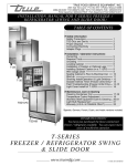
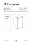
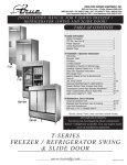
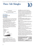
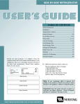
DESIGN GUIDE
B U I LT- I N
REFRIGERATORS
S AVO R T H E P E R F O R M A N C E . ™
CONTENTS
DESIGN OPTIONS
2
MODEL SPECIFICATIONS
4
INSTALLATION GUIDE
5
CUTOUT DIMENSION SPECIFICATIONS
6
PROPER POSITIONING
7
PANEL INSTALLATION
9
FRAMED MODEL PANELS
10
OVERLAY MODELS
13
SIDE PANELS
16
SPECIAL CONSIDERATIONS
17
WARRANTY
19
S AVO R T H E P E R F O R M A N C E . ™
Important: Because of continuing product improvements, Jade reserves the right to change specifications without notice. Dimensional specifications are provided for planning purposes only.
For complete details, see installation instructions packed with product before selecting cabinetry, making cutouts or beginning installation.
#
THE JADE ™ BUILT-IN REFRIGERATOR
The Jade™ built-in refrigerator is the new choice in built-in
refrigeration excellence for discriminating homeowners — a choice
that’s backed by the solid reputation of Jade as a leader in the
development of innovative kitchen solutions. Now Jade continues
that tradition with a built-in refrigerator that is setting new
standards in style, storage and performance.
Personalization is the guiding principle behind every aspect of
the Jade™ built-in refrigerator design, from its variety of exterior
styling possibilities, to adaptable choices in interior storage, to
performance that exceeds expectations. It all begins with these
distinct styling options — our versatile overlay model featuring the
homeowner’s choice of custom panels and handles or our elegant
framed model featuring custom panels offset by sleek trim and
matching handles. Exterior customization continues with your
client’s choice of a dispenser or nondispenser model.
Adaptable interior storage enables the client to create and
recreate the space inside the refrigerator with ease. Adjustable
shelves and bins.
When it comes to performance, the Jade™ built-in refrigerator excels. The key to its superb performance edge is our
Professional Temperature Management™ System. This sophisticated multi-component system is highlighted by our variablespeed compressor and Optifresh™ storage drawers, two features
which help ensure precise temperatures for outstanding food
preservation.
that provide the best insulation and rigidity possible. A foursquare leveling system allows for each corner of the refrigerator
to be adjusted from the front of the unit for easier and more
precise leveling. And the acoustic design of our Ultra-Quiet sound
package ensures incredibly quiet performance.
You’ll also find that our built-in refrigerator is backed by one of
the best warranties in the industry. The Jade™ built-in refrigerator warranty provides parts and labor coverage for a full
three years from the original Purchase date. A five-year parts
and labor warranty and a six-through twelve-year parts warranty
covers major refrigeration components including the compressor,
evaporator, condenser, drier and connecting tubing.
This Design Guide outlines the unique features of the Jade™
built-in refrigerator and provides general guidelines for a smooth
installation process. Complete installation instructions are
shipped with each unit. Refer to these instructions when
preparing and installing all Jade® products. Should you have
unique design considerations or installation questions, you can
easily access comprehensive technical assistance and support
by calling Jade at 1-800-794-5233. Service hours are 8 a.m.–8 p.m.
Monday through Friday and 8 a.m.–5 p.m. Saturday (PT).
The excellence of the Jade™ built-in refrigerator design is also
evident in quality construction details like foamed-in-place doors
#1
DESIGN O PT I O N S
Refrigerators that satisfy a world of individual preferences.
Jade™ built-in refrigerators offer a variety of models with design
models do not include handles, you have the freedom to choose
options and interior options that can easily be personalized for
from a practically unlimited array of handle styles to match
each client. From our cool and cultured stainless steel refrigerator,
or complement the hardware on surrounding cabinetry. Non-
to the distinctive appeal of our overlay design, to the popular look
dispenser models or models with a black dispenser are available.
of the framed model, Jade has an option that will fit your client's
The 11" grille at the top and toe kickplate at the bottom also accept
dream kitchen perfectly (see illustrations below).
custom panels.
Stainless steel models with beautiful wrapped doors come
Framed models are offered with silver etched frames and
with stainless steel towel-bar handles. Nondispenser models
handles to complement the custom panels your client has chosen.
are available, as well as dispenser models with a sleek, black
Attractive full-length handles add sophistication to our framed
dispenser that enhances the professional look. A heavy-duty
models. Dispenser and nondispenser framed models are available.
11" stainless steel grille finishes the look.
On dispenser models, a black dispenser silver etched frame and
handles. An 11" grille at the top and a toe kickplate at the bottom
Overlay models utilize custom panels to convey an elegant,
seamless appearance unique to each client’s kitchen. Since these
STAINLESS STEEL MODEL WITH DISPENSER
(shown with stainless steel towel bar handles)
#2
OVERLAY MODEL WITH DISPENSER
(panels and handles not included)
FRAMED MODEL WITH DISPENSER
(panels not included; includes
extruded handles)
Filtered ice and water dispenser with sleek, backlit design provides
a distinctive look for built-in refrigerator dispenser models. The
PuriClean® filtration system delivers fresh, filtered water and crushed
or cubed ice anytime, and touch sensors activate with just a light
touch.
Stainless steel models feature a black dispenser surrounded
completely by the stainless steel of the door and covered with stainless steel overlay. Framed models can accept a freezer panel that fits
around all sides of the dispenser. Or, you may choose a custom decorator freezer panel to blend perfectly with your cabinetry on framed or
overlay models.
Installation considerations: Before the built-in refrigerator is
installed, it is important to make sure the unit shipped matches the
exact design that you have specified and ordered. When the unit
Dispenser (shown in stainless steel model)
arrives at the installation site, make sure the installer checks the
shipment carefully.
Each of the three design choices — stainless steel, overlay and framed — has distinct installation requirements, which means it is crucial
that the unit delivered matches your space and planning requirements. The shipping carton will be labeled with a model number that
will describe exactly the size, design, handle style, color and whether the unit is a dispenser or nondispenser model. Note that the 4th
position of the model number indicates the different styles. (See chart below for model number guide.)
Installation instructions are shipped with each unit. Follow those instructions when preparing the space, uncrating the unit, and when
installing any Jade™ built-in refrigerator. If you cannot locate the installation instructions, call Jade Customer Assistance toll-free at 1800-794-5233 (U.S. and Canada). Or visit the Customer Service section of www.jadeappliances.com to download complete instructions
quickly and easily.
3#
MODEL SPECIFICATIONS
JA D E ™ BUILT- I N R EF R I GERATO R M O D E L S
SIZE
STYLE
TYPE
HANDLE & TRIM COLOR
MODEL
48"
STAINLESS STEEL
DISPENSER
Stainless Steel Handle/No Trim
RJRS4880
NON-DISPENSER
Stainless Steel Handle/No Trim
RJRS4870
DISPENSER
No Handle/Silver Etched
RJRS4881
NON-DISPENSER
No Handle/Silver Etched
RJRS4871
DISPENSER
Silver Etched
RJRS4882
NON-DISPENSER
Silver Etched
RJRS4872
DISPENSER
Stainless Steel Handle/No Trim
RJRS4280
NON-DISPENSER
Stainless Steel Handle/No Trim
RJRS4270
DISPENSER
No Handle/Silver Etched
RJRS4281
NON-DISPENSER
Silver Etched
RJRS4271
DISPENSER
Silver Etched
RJRS4282
NON-DISPENSER
Silver Etched
RJRS4272
OVERLAY
FRAMED
42"
STAINLESS STEEL
OVERLAY
FRAMED
D IS PE N S E R M O D EL I N T ER I O R CA PACI TI E S
STAINLESS STEEL MODELS
with stainless steel towel bar handles
OVERLAY MODELS
FRAMED MODELS
Interior Capacities — cu. ft. (cu. m)
Total Volume
Refrigerator Compartment Volume
Freezer Compartment Volume
Total Shelf Area — sq. ft. (sq. m)
Kilowatt-Hours Per Year
48” MODELS
42” MODELS
RJRS4880
RJRS4280
RJRS4881
RJRS4882
RJRS4281
RJRS4282
30.7
18.3
12.4
27.3
790.0
26.0
15.4
10.6
22.8
732.0
N O N D IS PE NS ER MO D EL I N T ER I O R CA PACI TI E S
STAINLESS STEEL MODELS
with stainless steel towel bar handles
OVERLAY MODELS
FRAMED MODELS
Interior Capacities — cu. ft. (cu. m)
Total Volume
Refrigerator Compartment Volume
Freezer Compartment Volume
Total Shelf Area — sq. ft. (sq. m)
Kilowatt Hours Per Year
4
48” MODELS
42” MODELS
RJRS4870
RJRS4270
RJRS4871
RJRS4872
RJRS4271
RJRS4272
30.1
18.3
11.8
29.4
689.0
25.5
15.4
10.1
26.8
661.0
IN STAL L AT I O N G U I DE – GENERAL CONSIDERATIONS
Even though Jade™ built-in refrigerators are available in a wide
range of design styles and configurations, the basic installation
planning information for all models has things in common. After
the decision has been made to install a Jade™ built-in refrigerator, be sure to review the installation requirements for the model
design chosen.
Make sure the opening where the unit will be installed is
properly prepared. Refer to Figure 1. Also check placements
for the electrical outlet and water line as shown in Figure 1.
(48") 47 1/2"/120.7 cm
(42") 41 1/2"/105.4 cm
17.78 cm
5.08 cm
10.16 cm
(48"/42")
83 3/4"
212.7cm
Plumbing Requirements
• Rough in the water line for the location (FIG. 1).
• Connect a 1⁄4" (0.64 cm) copper line to the house water supply
in compliance with local codes and ordinances.
• Use a shutoff valve between the refrigerator and water
supply. The shutoff should be a drilled saddle valve. Do not
use a self-tapping valve.
• The icemaker operates on 30 — 120 PSI.
• Route the water line within 1⁄2" (1.3cm) of the wall and no higher
than 3" (7.6 cm) from the floor. Allow at least 3' (0.91 m) of excess
copper tubing outside the wall for easy connection to the
water valve.
IMPORTANT TIP: In homes with a reverse-osmosis water
treatment system, remove the water inlet connector from
the yellow valve and attach to the blue valve. Make sure the
water filter bypass plug is in place.
191.8 cm
3 /2"
8.89cm
1
15.24 cm
Electrical Connection
This appliance is designed to operate on a normal 115 volt, 15 amp,
60 cycle line. There should be a separate, grounded circuit serving
this appliance only. Do not use an extension cord. Do not use any
device that will alter the electrical performance of this appliance.
For the placement of the electrical outlet, refer to Figure 1. Do not
use a ground fault circuit interrupter.
7.62 cm
60.96 cm
Uncrating The Unit
Uncrate the unit. Remove the lower shipping bolts and brackets.
Slide the unit off of the crate base. Remove and save the
7.62 cm
lower toe kickplate, anti-tipping brackets and mounting hardware
(FIG. 2a). Remove the upper cover (this will help when moving the
unit) (FIG. 2b).
For the door to open properly, it must be able to open at least
90 degrees. For installation in a corner, a 2" (5.1cm) filler strip is
required to ensure the 90-degree opening. Be sure to add the
filler strip width to your finished rough-in dimension.
The floor under the refrigerator has to be level with the
surrounding floor. To protect the floor when moving the refrigerator, place cardboard or a carpet remnant with the backing placed
up on the floor.
FIG. 2a
IMPORTANT TIP: Refer to the illustrations at the end of this
section for details on door openings and filler-size alternatives.
FIG. 2b
Important: Because of continuing product improvements, Jade reserves the right to change specifications without notice. Dimensional specifications are provided for
planning purposes only. For complete details, see installation instructions packed with product before selecting cabinetry, making cutouts or beginning installation.
5
INSTALLATION GUIDE – CUTOUT DIMENSION SPECIFICATIONS
C
TOP VIEW
B
A
H
F
I
J
K
D
E
G
Exterior Dimensions
Model Numbers
48" STAINLESS STEEL
48" OVERLAY
48" FRAMED
42" STAINLESS STEEL
42" OVERLAY
42" FRAMED
RJRS4880
RJRS4881
RJRS4882
RJRS4280
RJRS4281
RJRS4282
RJRS4870
RJRS4871
RJRS4872
RJRS4270
RJRS4271
cm
in.
cm
in.
cm
in.
cm
in.
cm
in.
cm
A. Cutout Height
83 3⁄4
212.7
83 3⁄4
212.7
83 3⁄4
212.7
83 3⁄4
212.7
83 3⁄4
212.7
83 3⁄4
212.7
B. Cutout Width
47 1⁄2
120.7
47 1⁄2
120.7
47 1⁄2
120.7
41 1⁄2
105.4
41 1⁄2
105.4
41 1⁄2
105.4
C. Cutout Depth
24
61.0
24
61.0
24
61.0
24
61.0
24
61.0
24
61.0
D. Height To Top Of Cabinet †
83 1⁄16
210.9
83 1⁄16
210.9
83 1⁄16
210.9
83 1⁄16
210.9
83 1⁄16
210.9
83 1⁄16
210.9
E. Height To Top Of Grille
83 3⁄8
211.8
83 3⁄8
211.8
83 3⁄8
211.8
83 3⁄8
211.8
83 3⁄8
211.8
83 3⁄8
211.8
F. Width (Cabinet)
47 1⁄4
120.0
47 1⁄4
120.0
47 1⁄4
120.0
41 1⁄4
104.8
41 1⁄4
104.8
41 1⁄4
104.8
G. Width (Doors Closed)
48 1⁄16
122.1
48 1⁄16
122.1
48 1⁄16
122.1
42 1⁄16
106.8
42 1⁄16
106.8
42 1⁄16
106.8
H. Depth Excl. Handles (Closed)
25 ⁄4
64.1
25 ⁄4
64.1
25 ⁄4
64.1
25 ⁄4
64.1
25 ⁄4
64.1
25 1⁄4
64.1
I. Depth Incl. Handles (Closed)
26 5⁄8
67.6
26 3⁄8
67.0††
26 5⁄8
67.2
26 3⁄8
67.0††
J. Depth (Fresh Food Door
Open 90°)
52 9⁄16
133.5
52 9⁄16
133.5
48 3⁄4
123.8
48 3⁄4
123.8
K. Width (Doors Open 90°,
Including Handles)
50 3⁄4
51 7⁄8
128.9
131.8
50 1⁄4
127.6 †††
44 3⁄4
45 7⁄8
113.7
116.5
44 1⁄4
112.4†††
1
1
NA
52 9⁄16
NA
†
1 1⁄4" (3.2 cm) vertical adjustment for leveling and height adjustments.
††
Add 1" (2.5 cm) to depth (I) for extended handle kit, if used, on framed model.
†††
133.5
1
1
1
NA
48 3⁄4
Add 2" (5.1 cm) to width (K) for extended handle kit, if used, on framed model.
Important: Because of continuing product improvements, Jade reserves the right to change specifications without notice. Dimensional specifications are provided for
planning purposes only. For complete details see installation instructions packed with product before selecting cabinetry, making cutouts or beginning installation.
6
RJRS4272
in.
NA
123.8
IN STAL L AT I O N G U I DE – PROPER POSITIONING
Blocking and/or Anchoring the Refrigerator
If there is a solid soffit above the unit and the clearance is 1"
(2.5 cm) or less, you will not need to block the unit. For installations
with clearances of more than 1" (FIG. 3), you must use the anti-tipping 2 x 4 and brackets provided (FIG. 4).
More than 1" (2.5 cm) Clearance:
Use the anti-tipping kit provided with the shipping crate. Locate
and mark the two wall studs behind the unit. Mark where the
"L" brackets and 2 x 4 will be located and drill two 1⁄8" pilot holes.
Locate the proper height to clear the unit. The space between the
top of the unit and bottom of the wood block must not exceed
1
⁄4" (0.6 cm). Secure the L brackets into the wall studs using the
provided screws ( 1 ). Make sure the screws will extend 7⁄8" (2.2cm)
into the wall studs. Align the pilot holes with the L brackets and
secure the 2 x 4 with the screws provided ( 2 , 3 ).
FIG. 3
Adjusting Door Hinges
FIG. 4
Check to make sure the doors are properly adjusted. If not,
adjust the top and bottom hinges. The hinges are slotted for
side-to-side movement. First, remove the small Phillips screw
on the door hinge, which is inboard on the hinge, and throw
it away. Adjust the upper and lower hinges by loosening the
three large Torx screws. Tighten the screws after the doors are
adjusted. Door handles can be adjusted to level top handle
trim. The doors are slotted for handle alignment.
7
INSTAL L AT I O N G U I DE – P ROPER POSITIONING
Leveling
Slide the unit in place and raise the front and rear
levelers until the unit touches the brackets. Use a
3
⁄8" socket for raising and lowering the unit. On each
wheel housing, there are two 3⁄8" hex bolts. On the
left side, the outside bolt will move the rear leveler
and the inside bolt will move the front leveler. On
the right side, the outside bolt will move the front
leveler and the inside bolt will move the rear leveler
(FIG. 5). The front levelers must be in contact with
the floor. To raise the leveling legs, turn the hex
screw counterclockwise. Place level on lower ledge
of the machine compartment. Level the unit front to
back and side to side to prevent tipping of the unit
(FIG. 4). Install the kickplate. The kickplate must be
removable to allow access to the water valves. In
the machine compartment there is an on/off power
switch. Make sure the switch is in the ON position
and switch lever is up. Install the upper cover.
FIG. 5
1 1/4" (3.2 cm) vertical adjustment for leveling and height adjustments.
Optional: If you are attaching
the unit to cabinetry, drill three 3⁄16"
holes through both outer trims. Drill 1⁄8"
pilot holes into the cabinetry. Install screws.
Additionally, if the depth/height of opening is excessive, use the steel
hanger strap. Double over strap at the anchor points to secure cabinet.
8
INSTAL L AT I O N G U I DE – PA NEL INSTA LLATION
Integrating the Refrigerator into Kitchen Cabinetry
If the customer has chosen a stainless steel model, it will arrive complete with wrapped stainless steel doors and stainless steel towel bar
handles. You will not have to install panels. Jade offers 42" and 48" dispenser and nondispenser models with the stainless steel design.
Framed or overlay models require the installation of custom or decorative panels to give the refrigerator the personalized look the
consumer has chosen for the kitchen. Framed models are shipped with full-length extended handles (see below). Overlay models are
designed to use the custom hardware the consumer has chosen separately; handles are not included with this type of product.
Framed Models
Framed models can accept either a framed panel or a custom
Framed Panels 1/4" thick or less
Framed Raised Panels thicker than 1/4"
Trim Reveal 1/4"
Trim Reveal 1/4"
decorator panel. If the thickness of the framed panel to be
installed is less than 1⁄4" (0.6 cm), a sheet of shim material to build
Route down to
/4" thickness
1
1
/4" Panel
the total thickness to 1⁄4" (0.6 cm) must be used. Likewise, if the
framed panel is thicker than 1⁄4" (0.6 cm), you must rout an edge
around the panel to ensure the panel fits properly. This is illus-
FIG. 6
FIG. 7
trated in Figures 6 and 7.
Important: Because of continuing product improvements, Jade reserves the right to change specifications without notice. Dimensional specifications are provided for
planning purposes only. For complete details, see installation instructions packed with product before selecting cabinetry, making cutouts or beginning installation.
9
INSTAL L AT I O N G U I DE – F RA M ED M OD EL PA NELS
A. 1/4" (10.6 cm) Framed Panel Specifications for Framed Models
Jade offers 42" and 48" dispenser and nondispenser models with the framed
design. The framed trim remains visible when using the framed panel installation. These models accommodate up to a 1/4" (0.6 cm) panel depth.
Nondispenser
Freezer Panel
Refer to page 20 for toe kickplate panel information.
If installing side panels, refer to page 19.
42"-Wide Cabinet
in.
cm
(A) Grille Panel
W Width
H Height
(B) Freezer Dispenser Panel
W Width
W1 Width
W2 Width
H Height
H1 Height
H2 Height
(C) Freezer Nondispenser Panel
W Width
H Height
(D) Refrigerator Panel
W Width
H Height
48"-Wide Cabinet
in.
cm
40 1/4
8 3/4
102.24
22.23
46 1/4
8 3/4
117.47
22.23
15 1/16
2
14 1/2
69 1/8
34 1/16
48 1/8
38.26
5.08
36.83
175.58
86.52
122.24
17 5/16
2
14 1/2
69 1/8
34 1/16
48 1/8
43.97
5.08
36.83
175.58
86.52
122.24
15 1/16
69 1/8
38.26
175.58
17 5/16
69 1/8
43.97
175.58
22 5/16
69 1/8
56.67
175.58
26 1/16
69 1/8
66.20
175.58
! CAUTION
Refrigerator Panel Weight Not to Exceed
50 lbs. (22.36 kg)
Total Freezer Panel Weight Not to Exceed
33 lbs. (14.96 kg)
Grille Panel Weight Not to Exceed 22 lbs.
(9.97 kg)
Important: Because of continuing product improvements, Jade reserves the right to change specifications without notice. Dimensional specifications are provided for
planning purposes only. For complete details see installation instructions packed with product before selecting cabinetry, making cutouts or beginning installation.
10
INSTAL L AT I O N G U I DE – FRA M ED M OD EL PA NELS
B. Decorator Panel Specifications for Framed Models
Decorator panels for framed models cover the door trim for an
attractive, seamless look that flows into the overall design of the
room. Framed models include full-length extruded handles, unlike
overlay models. Attention must be paid
to hand clearance, or the depth of
space between the decorator panel and
the built-in handle. (See figures 12 and 13
on page 17 for more information.)
This application is often accomplished
by using three panels: the decorative
front panel, a spacer panel of .10" (2.5
cm) thickness and a 1/4" (0.6 cm) backer
panel. Other options to achieve this
look (such as using one panel routed for
different dimensions) may be available
from your cabinet manufacturer.
Jade offers 42" and 48" dispenser and
nondispenser models with the framed
design.
Refer to page 20 for toe kickplate panel information.
If installing side panels, refer to page 19.
/4" (1.9 cm) Max.
3
3
/4" (1.9 cm) Max.
.10" (2.5 mm)
1
/4" (0.6 cm)
.10" (2.5 mm)
1
/4" (0.6 cm)
FIG. 9
FIG. 8
Figure 8 shows a cross-section view of the three-panel
assembly indicating the placement of the door/grille trim.
Figure 9 gives a rear view of the three-panel assembly and
important dimensions that are standard for framed and overlay
models. For routed-panel applications, the backer panel
dimension should not exceed 7⁄32" (0.55 cm) thickness.
Important: Because of continuing product improvements, Jade reserves the right to change specifications without notice. Dimensional specifications are provided for
planning purposes only. For complete details, see installation instructions packed with product before selecting cabinetry, making cutouts or beginning installation.
11
INSTAL L AT I O N G U I DE – F RA M ED M OD EL PA NELS
BACKER PANEL
(A) Grille Panel
W Width
H Height
(B) Freezer Dispenser Panel
W Width
W1 Width
W2 Width
H Height
H1 Height
H2 Height
(C) Freezer Nondispenser Panel
W Width
H Height
(D) Refrigerator Panel
W Width
H Height
SPACER PANEL
(A) Grille Panel
W Width
H Height
(B) Freezer Dispenser Panel
W Width
W1 Width
W2 Width
H Height
H1 Height
H2 Height
(C) Freezer Nondispenser Panel
W Width
H Height
(D) Refrigerator Panel
W Width
H Height
FRONT DECORATOR PANEL
(A) Grille Panel
W Width
H Height
(B) Freezer Dispenser Panel
W Width
W1 Width
W2 Width
H Height
H1 Height
H2 Height
(C) Freezer Nondispenser Panel
W Width
H Height
(D) Refrigerator Panel
W Width
H Height
12
42"-Wide Cabinet
in.
cm
48"-Wide Cabinet
in.
cm
NOTES:
1. Use countersink screws for attaching the
backer panel to the front panel.
40 1/4
8 3/4
102.24
22.23
46 1/4
8 3/4
117.48
22.23
2. On 42" custom panels, watch location of
handle mounting due to undercut of front
panel.
15 1/16
2
14 1/2
69 1/8
34 1/16
48 1/8
38.26
5.08
36.83
175.58
86.52
122.24
17 5/16
2
14 1/2
69 1/8
34 1/16
48 1/8
43.97
5.08
36.83
175.58
86.52
122.24
3. For freezer dispenser front panels, remove
fountain trim and tape it to the backside
of the backer panel. Note: Recycle symbol
should be visible and located at the bottom.
15 1/16
69 1/8
38.26
175.58
17 5/16
69 1/8
43.97
175.58
22 5/16
69 1/8
56.67
175.58
26 1/16
69 1/8
66.20
175.58
in.
cm
in.
cm
39 1/4
7 3/4
99.7
19.69
45 1/4
7 3/4
114.94
19.69
14 1/16
2
14 1/2
68 1/8
34 1/16
48 1/8
35.72
5.08
36.83
173.04
86.52
122.24
16 5/16
2
14 1/2
68 1/8
34 1/16
48 1/8
41.43
5.08
36.83
173.04
86.52
122.24
14 1/16
68 1/8
35.98
173.04
16 5/16
68 1/8
41.43
173.04
21 5/16
68 1/8
54.13
173.04
25 1/16
68 1/8
63.66
173.04
in.
cm
in.
cm
40 1/4
8 3/4
102.24
22.23
46 1/4
8 3/4
117.48
22.23
14 7/8
2 1/4
14 1/4
69 1/4
34 5/16
47 13/16
37.78
5.72
36.20
175.90
87.15
121.44
17 1/8
2 1/4
14 1/4
69 1/4
34 5/16
47 13/16
43.50
5.72
36.20
175.90
87.15
121.44
14 7/8
69 1/4
37.78
175.90
17 1/8
69 1/4
43.50
175.90
22 1/8
69 1/4
56.20
175.90
26 7/8
69 1/4
68.26
175.90
4. You may want to remove any additional
material on the backer panel when used in
conjunction with a front panel. Remove 1/32"
of thickness and 1/2" of width on the inside
surface of the backer panel. This will help
ease assembly of the panel assembly onto
the door.
Backer Panel Thickness 1/4" (0.64 cm)
Spacer Panel Thickness 0.100" (0.25 cm)
If Raised Panel is Used Overall Front Panel
Thickness Not to Exceed 1 1/4" (3.18 cm)
INSTAL L AT I O N G U I DE – OV ERLAY M OD ELS
Overlay Models
The decorator panels for overlay models cover the door trim for an attractive, seamless look that flows into the overall design of the
room. This application is often accomplished by using three panels: the decorative front panel, a spacer panel of .10" (2.5 mm) thickness,
and a 1⁄4" (0.6 cm) backer panel. Other options to achieve this look (such as using one panel routed for different dimensions) may be
available from your cabinet manufacturer.
Jade offers 42" and 48" dispenser and nondispenser models with the overlay design.
Decorator Panel Specifications for Overlay Models (See illustration on page 14.)
BACKER PANEL
(A) Grille Panel
W Width
H Height
(B) Freezer Dispenser Panel
W Width
W1 Width
W2 Width
H Height
H1 Height
H2 Height
(C) Freezer Nondispenser Panel
W Width
H Height
(D) Refrigerator Panel
W Width
H Height
SPACER PANEL
(A) Grille Panel
W Width
H Height
(B) Freezer Dispenser Panel
W Width
W1 Width
W2 Width
H Height
H1 Height
H2 Height
(C) Freezer Nondispenser Panel
W Width
H Height
(D) Refrigerator Panel
W Width
H Height
FRONT DECORATOR PANEL
(A) Grille Panel
W Width
H Height
(B) Freezer Dispenser Panel
W Width
W1 Width
W2 Width
H Height
H1 Height
H2 Height
(C) Freezer Nondispenser Panel
W Width
H Height
(D) Refrigerator Panel
W Width
H Height
42"-Wide Cabinet
in.
cm
1
48"-Wide Cabinet
in.
cm
1
40 /4
8 3/4
102.24
22.23
46 /4
8 3/4
117.48
22.23
16 1/4
2
14 1/2
69 1/8
34 1/16
48 1/8
41.28
5.08
36.83
175.58
86.52
122.24
18 1/2
2
14 1/2
69 1/8
34 1/16
48 1/8
46.99
5.08
36.83
175.58
86.52
122.24
16 1/4
69 1/8
41.28
175.58
18 1/2
69 1/8
46.99
175.58
23 1/2
69 1/8
59.69
175.58
27 1/4
69 1/8
69.22
175.58
in.
cm
in.
cm
39 1/4
7 3/4
99.70
19.69
45 1/4
7 3/4
114.94
19.69
15 1/4
2
14 1/2
68 1/8
34 1/16
48 1/8
38.74
5.08
36.83
173.04
86.52
122.24
17 1/2
2
14 1/2
68 1/8
34 1/16
48 1/8
44.45
5.08
36.83
173.04
86.52
122.24
15 1/4
68 1/8
38.74
173.04
17 1/2
68 1/8
44.45
173.04
22 1/2
68 1/8
57.15
173.04
26 1/4
68 1/8
66.68
173.04
in.
cm
in.
cm
40 1/4
8 3/4
102.24
22.23
46 1/4
8 3/4
117.48
22.23
16 7/16
2 1/4
14 1/4
69 1/4
34 5/16
47 13/16
41.75
5.72
36.20
175.90
87.15
121.44
18 3/4
2 1/4
14 1/4
69 1/4
34 5/16
47 13/16
47.63
5.72
36.20
175.90
87.15
121.44
16 7/16
69 1/4
41.75
175.90
18 3/4
69 1/4
47.63
175.90
23 3/4
69 1/4
60.33
175.90
27 1/2
69 1/4
69.85
175.90
NOTES:
1. Use countersink screws for attaching the
backer panel to the front panel.
2. On 42" custom panels, watch location of
handle mounting due to undercut of front
panel.
3. For freezer dispenser front panels, remove
fountain trim and tape it to the backside
of the backer panel. Note: Recycle symbol
should be visible and located at the bottom.
4. You may want to remove any additional
material on the backer panel when used in
conjunction with a front panel. Remove 1/32"
of thickness and 1/2" of width on the inside
surface of the backer panel. This will help
ease assembly of the panel assembly onto
the door.
Backer Panel Thickness 1/4" (0.64 cm)
Spacer Panel Thickness 0.100" (0.25 cm)
If Raised Panel is Used Overall Front Panel
Thickness Not to Exceed 1 1/4" (3.18 cm)
Important: Because of continuing product improvements, Jade
reserves the right to change specifications without notice.
Dimensional specifications are provided for planning purposes
only. For complete details, see installation instructions packed
with product before selecting cabinetry, making cutouts or
beginning installation.
13
INSTALLATION GUIDE – DECORATOR PANELS
Installing Decorator Panels
Be aware that panels used on refrigerators with the framed or overlay design have the potential for coming into contact with adjacent
cabinets and/or countertops when the refrigerator doors are opened. You will want to be mindful of the surrounding cabinetry and
space limitations when planning for decorator panels.
Refer to the 90° door stop information in Figure 18 on page 21.
Grille Panels
A decorator grille panel that matches the decorator door panels
! CAUTION. Do not exceed the panel dimensions shown in the
charts on pages 15 and 16 for the grille panel. If the decorator
may be used to replace the standard grille shipped on the
panel is larger than specified, it may restrict the airflow to the
unit. This allows the refrigerator to integrate completely into
compressor and condenser area, which may cause the unit to
the surrounding cabinetry.
function improperly.
Installation of Panels (Framed or Overlay Models)
1. Begin by removing the door handle or trim piece. A magnetic-backed molding hides the handle or overlay trim screws. Use the adhesive
side of the packaging tape on the magnetic-backed molding to pull it away from door (FIG. 10a).
2. Remove the screws with a Phillips screwdriver (FIG. 10b). Slide the panel into position. The panel needs to be under the trim. Install the
handle. Replace the molding in the channel and reset the magnetic-backed molding.
3. To install the panel on the grille, remove the screws on the top and bottom of the upper cover (FIG. 10c). DO NOT REMOVE the foam.
4. Slide the panel into place and replace screws (FIG. 10d). If the thickness of the panel is less than a 1/4" (0.6 cm), back it up with a sheet of shim
material to obtain 1/4" (0.6 cm) thickness. Cardboard backer is recommended for stainless steel application. For panel size, refer to pages
9 — 13.
! CAUTION
Do not drive screws or sharp objects into door panels.
3
Do not pinch door seal when reinstalling handle.
4
1
2
FIG. 10d
FIG. 10c
! CAUTION
When attaching a raised wood panel of
1
/2" (1.3 cm) or thicker secure the raised panel to
the back of the grille cover frame. Use four #8 or
FIG. 10a
14
FIG. 10b
similar screws. See illustration for approximate locations.
INSTAL L AT I O N G U I DE – INSTA LLING PA NELS
O N D ISPENSER M OD ELS
Freezer Dispenser Panel Installation
1.
2.
3.
Power switch needs to be off. Switch is
located in machine compartment area
(see User Guide).
Remove magnetic strip on door handle.
Use of tape may be required to remove
magnetic strip. (See FIG. 10a on page 17.)
Remove four Phillips screws to remove
door handle/trim. (See FIG. 10b on
page 17.)
(Refer to numbered illustrations for steps 4 — 10)
4.
Remove the spill tray grille from the
fountain.
5. Remove the two #15 Torx machine screws,
that retain the stainless steel splashguard.
Remove the splashguard.
6. Remove the two #15 long plastic Torx
screws that retain the fountain control
panel. Slide control panel down to remove.
Disconnect the electrical terminals
going to the fountain control panel. Tuck
dispenser terminal inside to avoid
interference.
7. Remove the four #15 plastic collar Torx
screws from the fountain/escutcheon
collar.
8. Place the fountain/escutcheon collar
onto the backer panel. Use tape to hold
in place.
9. Open the freezer door and slide panel
onto the door.
10. The holes in the fountain/escutcheon
collar should line up with the mounting
holes in the door panel. Reverse
instructions 7 to 1: Replace the four
#15 plastic collar Torx screws in connect
the fountain escutcheon collar, the
electrical terminals, and so on.
4
5
6
7
8
9
10
15
INSTAL L AT I O N G U I DE – S ID E PA NELS
/4" side panel fitted up to
the cabinet trim (top view)
of freezer side.
/4" side panel fitted up to
the cabinet trim (top view)
of refrigerator side.
1
Installing Side Panels
1
backside of unit
backside of unit
If you are using side panels with the Jade™ built-in refrig-
#8-32 1/2" screw
#8-32 /2" screw
1
erator, they will need to be ⁄4" (0.6 cm) thick. Slide the
1
panel into position and secure with screws as indicated
/2" (1.27 cm) spacers
on the side of machine
compartment (3/16"
(0.48 cm) below the
machine compartment)
1
/16" (0.48 cm)
spacers
3
by the shaded area (FIG. 11a). A ⁄16" spacer is required
3
between the cabinet and side panel (FIG. 11b). A 1⁄2" thick by
10 1⁄4 " tall spacer is required if the side panel extends up
into the machine compartment area on the refrigerator
side (FIG. 11c).
1
/4" (0.64 cm) side panel
1
/4" (0.64 cm) side panel
freezer side of unit
refrigerator side of unit
door
door
FIG. 11b
FIG. 11c
82 13/16"
(210.3 cm)
1 3/8" (3.5 cm)
2 7/16" (6.9 cm)
FIG. 11a
16
3
/8" (0.95 cm)
2 1/2" (6.35 cm)
24" (61 cm)
INSTALLATION GUIDE – SPECIAL CONSIDERATIONS
Special Considerations
The illustrations on this page may be useful to help
FIG.12
you understand some of the situations you may
2 7/16" Standard Handle
3 7/16" Optional Extended Handle
face as you design and install the various models of
Jade™ built-in refrigerators.
FIG. 13
Figures 12 — 14 demonstrate handle placement for
framed models. Figure 14 also shows the optional
handle extension as referenced by the stair-stepped
portion of the drawing.
FIG. 14
1
/2 "
1
/4"
3
/4 "
1
/4 "
1 1/4"
Allow min. of 2 5/16"
Optional Extended
Handle Kit
Figure 15 provides information for using a custom panel in the toe kickplate
area on overlay or framed models.
Panel thicker than 3/16"
Angle cut for thicker plates
FIG. 15
Nondispenser
6 1/4"
5 5 /8 "
/16" TYP
15
(A) Three /16" holes may be used to attach panel to cabinet
3
4 13/16"
7
/8"
5
2 /16" TYP
/4" TYP
3
Cutout for Dispenser
/16"
3
1 /16"
13
DIA. 1/4" TYP
1 /8" TYP
1
3"
R. 1/2"
Allow relief here for
dispenser models with
panels thicker than 3/16"
3 3/4"
(48) 46 7/8"
(42) 40 7/8"
Handle Considerations for Overlay Models
If the customer has specified a Jade™ built-in refrigerator overlay model, the unit will be shipped without
handle hardware. Handle hardware that the customer has specified to match the overall decorating scheme must
be provided separately at the job site.
Before installing the custom panel assembly, the custom
handle hardware must be installed. It is recommended that
handles with larger D-style pulls be used. If the screws that
are used have thick heads, the screws will need to be
countersunk into the panel before it is put into place.
IMPORTANT TIP: Jade advises that single-pull knobs not
be used on built-in refrigerator overlay models.
20" (50.8 cm)
Important: Because of continuing product improvements, Jade reserves the right to change specifications without notice. Dimensional specifications are provided for
planning purposes only. For complete details, see installation instructions packed with product before selecting cabinetry, making cutouts or beginning installation.
17
INSTALLATION GUIDE – SPECIAL CONSIDERATIONS
Figures 16 and 17 let you see what considerations you
need to make for any custom panel applications, and
how they may interact with adjacent cabinets and/or
countertops. Also refer to the Installation Guidelines for
framed and overlay models on pages 14 — 17.
90˚ Door Stop
Both doors are designed to open 135˚. To restrict one or both
doors to a 90˚ opening, use the door stops supplied in this kit.
FIG. 18
90º
With the doors closed, screw a door stop into the
underside of the lower hinge plate as illustrated above.
Tool Requirements:
Door
Open
90º
Tape measure
Level
Stud finder
Drill with various bits
Socket set
Utility knife
Magnetic extended screwdriver
Phillips screwdriver
Torx bit
Cardboard, carpet remnant or other protective material for flooring
Steel hanger strap
FIG. 16
Installation Checklist:
135º
INSTALLER
Doors
q
q
q
q
q
Handles are solidly attached to doors.
Doors seal completely to refrigerator cabinet.
Door handle alignment is correct (framed models).
Door seals are not pinched.
Screws/sharp objects have not been driven into the doors.
Leveling
Door Open
135º
q
q
q
L brackets are secured to 2x4 wood block.
Stabilizing legs are against floor. Cabinet is secure.
Toe kickplate is properly attached to refrigerator and
aligned with floor.
Icemaker
q
FIG. 17
q
q
q
q
18
Water supply to refrigerator is turned on and lines have
been flushed.
Water leaks are not present at connection between
house-hold water supply and refrigerator.
Icemaker arm is down for ice production.
PuriClean® ice and water filtration system is installed
correctly, if applicable.
Water has been purged from the fountain on dispenser models.
JAD E™ B U I LT-I N R E F R I G ERATOR WA RRA NT Y
Full Three-Year Warranty
For three (3) years from the date of original retail purchase, any part which fails in normal home use will be repaired or replaced free of charge.
Icemaker – when supplied with the refrigerator, the icemaker will be considered part of the refrigerator for warranty purposes.
Limited Five-Year Warranty – Major Refrigeration Components
For five (5) years from the date of original retail purchase, any part of the sealed refrigeration system (consisting of the compressor, evaporator,
condenser, drier and connecting tubing) which fails in normal home use will be repaired or replaced, at the manufacturer’s option, free of charge.
Mileage and transportation charges, if required, shall be the responsibility of the owner.
Limited Warranty – Major Refrigeration Components
Sixth Through Twelfth Year: After the fifth year from the date of original retail purchase, through the end of the twelfth year, the manufacturer will repair
or replace, at its option, free of charge for the part itself, any part of the sealed refrigeration system (consisting of the compressor, evaporator, condenser,
drier and connecting tubing) which fails in normal home use, with the owner paying all other costs, including labor, mileage and transportation.
Limited Warranty – PuriClean® Water Filter
With regard to the water filter cartridge, any part of the water filter cartridge which fails due to a defect in workmanship or materials will be replaced
for a period of thirty days from the date of original purchase. This is a full 30-day warranty, and during this warranty period, we will also provide free
of charge, all labor and in-home service required to replace the defective part.
PLEASE NOTE: The full warranty and the limited warranties apply when the refrigerator is located in the United States or Canada. Refrigerators
located elsewhere are covered by the limited warranties only, including parts that fail during the first three years.
Limitations of Liability
The warrantor shall not be liable for any incidental or consequential damages, including food loss. Some states do not allow the exclusion or limitation of
consequential damages, so the above limitation or exclusion may not apply to you.
The specific warranties expressed above are the ONLY warranties provided by the manufacturer. This warranty gives you specific legal rights, and
you may also have other rights that vary from state to state.
TO RECEIVE WARRANTY SERVICE
WHAT IS NOT COVERED BY THESE WARRANTIES
To locate an authorized service company in your area, contact the Jade dealer from
whom your appliance was purchased; or call Customer Assistance at the number listed
below. Should you not receive satisfactory warranty service, please call or write:
1.
Conditions and damages resulting from any of the following:
a. Improper installation, delivery or maintenance.
b. Any repair, modification, alteration or adjustment not authorized by the
manufacturer or an authorized servicer.
Maytag Appliance Sales Company
P.O. Box 2370
c. Misuse, abuse, accidents or unreasonable use.
Cleveland, TN 37320-2370
d. Incorrect electric current, voltage or supply.
U.S. and CANADA 1-866-459-6298
e. Improper setting of any control.
U.S. customers using TTY for deaf, hearing impaired or speech impaired, call
1-800-688-2080.
2. Warranties are void if the original serial numbers have been removed, altered
or cannot be readily determined.
NOTE: When writing about an unsolved service problem, please include the following
information:
a. Your name, address and telephone number.
b. The model number, serial number and revision number of your refrigerator
(found on the top front interior of the refrigerator compartment).
c. The name and address of your dealer and the date the appliance was bought.
d. A clear description of the problem you are having.
e. Proof of purchase (sales receipt).
3. Light bulbs.
4. Products purchased for commercial or industrial use.
5. The cost of service or service call to:
a. Correct installation errors.
b. Instruct the user on proper use of the product.
c. Transport the appliance to the servicer.
6. Consequential or incidental damages sustained by any person as a result of
any breach of these warranties.
Some states do not allow the exclusion or limitation of consequential or incidental
damages, so the above exclusion may not apply.
User’s Guides, service manuals and parts catalogs
are available from Customer Service.
NOTE: Some reverse-osmosis home water systems cause low water pressure. Low water
pressure can affect the water and ice dispensing system by causing small or hollow ice
cubes and slow water flow from the dispenser. Service problems related
to the home’s reverse-osmosis water system are not covered by the warranty.
S AVO R T H E P E R F O R M A N C E . ™
U.S. and foreign patents and patents pending. Specifications subject to change without notice.
For a dealer near you, visit www.jadeappliances.com or call 1-800-794-5233.
19