1
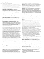
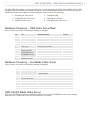
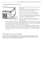
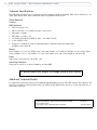
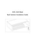
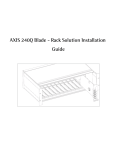
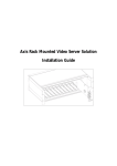
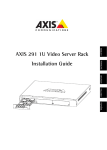
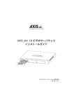
AXIS 241Q/S Blade - Rack Solution
Installation Guide
2
About This Document
use the equipment according to the instruction manual
This document is intended as an addendum to the video
server User’s Manual. It includes instructions for installing
the Axis Rack Mounted Video Server Solution on your
network. Later versions of this document will be posted to
the Axis Web site, as required.
Australia - This electronic device meets the requirements of
the Radio communications (Electromagnetic Compatibility)
Standard 1998 AS/NZS 3548. Compliance is not valid for
unshielded network cables.
Intellectual Property Rights - Axis AB has
intellectual property rights relating to technology embodied
in the product described in this document. In particular,
and without limitation, these intellectual property rights
may include one or more of the patents listed at
http://www.axis.com/patent.htm and one or more
additional patents or pending patent applications in the US
and other countries.
Legal Considerations - Camera surveillance can be
prohibited by laws that vary from country to country.
Check the laws in your local region before using this
product for surveillance purposes.
Electromagnetic Compatibility (EMC) - This
equipment generates, uses, and can radiate radio frequency
energy, and if not installed and used in accordance with the
instruction manual, may cause interference to radio
communications. Shielded cables should be used to ensure
compliance with EMC standards.
US - This equipment has been tested and found to comply
with the limits for a Class B digital device, pursuant to Part
15 of the FCC Rules. These limits are designed to provide
reasonable protection against harmful interference in a
residential installation. This equipment generates, uses and
can radiate radio frequency energy and, if not installed and
used in accordance with the instructions, may cause
harmful interference to radio communications. However,
there is no guarantee that interference will not occur in a
particular installation. If this equipment does cause harmful
interference to radio or television reception, which can be
determined by turning the equipment off and on, the user is
encouraged to try to correct the interference by one or
more of the following measures: Reorient or relocate the
receiving antenna. Increase the separation between the
equipment and receiver. Connect the equipment into an
outlet on a circuit different from that to which the receiver
is connected. Consult the dealer or an experienced radio/TV
technician for help.
Europe -
This digital equipment fulfills the
requirements for radiated emission according to limit B of
EN55022, and the requirements for immunity according to
EN55024 residential, commercial, and light industry.
Japan - This is a class B product based on the standard of
the Voluntary Control Council for Interference from
Information Technology Equipment (VCCI). If this is used
near a radio or television receiver in a domestic
environment, it may cause radio interference. Install and
AXIS COMMUNICATIONS
<Product
Name> Quick User’s Guide
Liability - Every care has been taken in the preparation of
this manual; Please inform your local Axis office of any
inaccuracies or omissions. Axis Communications AB cannot be
held responsible for any technical or typographical errors and
reserves the right to make changes to the product and manuals
without prior notice. Axis Communications AB makes no
warranty of any kind with regard to the material contained
within this document, including, but not limited to, the implied
warranties of merchantability and fitness for a particular
purpose. Axis Communications AB shall not be liable nor
responsible for incidental or consequential damages in
connection with the furnishing, performance or use of this
material.
Trademark Acknowledgments - Acrobat, Adobe, Boa,
Ethernet, IBM, Internet Explorer, LAN Manager, Linux,
Macintosh, Microsoft, Netscape Navigator, OS/2, UNIX,
Windows, WWW are registered trademarks of the respective
holders. Java and all Java-based trademarks and logos are
trademarks or registered trademarks of Sun Microsystems, Inc.
in the United States and other countries. Axis Communications
AB is independent of Sun Microsystems Inc.
Support Services - Should you require any technical
assistance, please contact your Axis reseller. If your questions
cannot be answered immediately, your reseller will forward
your queries through the appropriate channels to ensure a rapid
response. If you are connected to the Internet, you can:
•
•
download user documentation and firmware updates
find answers to resolved problems in the FAQ database.
Search by product, category, or phrases
• report problems to Axis support staff by logging in to your
private support area
Visit the Axis Support Web at www.axis.com/techsup
Battery Replacement - The Axis Rack Mounted Video
Server Solution uses a 3.0V CR2032 Lithium battery as the
power supply for its internal real-time clock (RTC). This battery
will, under normal conditions, last for a minimum of 5 years.
Low battery power affects the operation of the RTC, causing it
to reset at every power-up. A log message will appear when
battery replacement is required.. The battery should not be
replaced unless required! If the battery needs replacing, please
observe the following points:
• Caution! Danger of explosion if battery is incorrectly replaced
• Replace only with the same or equivalent battery, as
recommended by the manufacturer
• Dispose of used batteries according to the manufacturer's
instructions
AXIS 241Q/S Blade - Rack Solution Installation Guide
The Axis Video Server Rack can accommodate up to 12 rack-mounted Axis Video Servers (Blade Servers). This
installation guide describes the hardware installation of the Axis Rack Mounted Video Server Solution. The AXIS
241Q/S Video Server User’s Manual contains additional instructions on the following:
•
•
•
Installing the video server
Configuring the video server
Using the video server
•
•
•
Troubleshooting
Updating the software
Customizing the video server
Hardware Inventory - AXIS Video Server Rack
Please contact your dealer if anything is missing or damaged.
Qty
Item
Product Name/Title
1
Video server rack
AXIS Video Server Rack
5
Cover plates
Cover plate 12TE
1
Cover plate
Cover plate 6TE
2
Connectors
Terminal Connectors 6p
1
Power supply
Power Supply 19” 100W
1
Power Cable
Mains Cable IEC
1
Country-specific:
ensure that the correct adapter is used
Country
Europe
UK
US / Japan
Australia
Warranty Document
Hardware Inventory - Axis Blade Video Server
Please contact your dealer if anything is missing or damaged.
Qty
Item
Title/Variants
1
Video servers
AXIS 241Q Blade
AXIS 241S Blade
2
Connectors
1
Warranty Document
Terminal Connectors 14p
1
User’s Manual
AXIS 241Q/S User’s Manual
1
This Document
AXIS 241Q/S Blade - Rack Solution Installation Guide
Optional Accessory
ACC Y/C TO BNC CABLE (AXIS 241S Blade only)
AXIS 241Q/S Blade Video Server
Read the following information to familiarize yourself with the AXIS 241Q/S Blade video server, making
particular note of where the connectors and indicators are located.
3
4
AXIS 241Q/S Blade - Rack Solution Installation Guide
Control Button
See the AXIS 241Q/S User’s Manual for information on the use of the
control button.
Indicators
Network
Status
Power
Amber
Flashes for activity on a 10 Mbit/s network
Green
Flashes for activity on a 100 Mbit/s network
Red
Flashes rapid red for hardware error, together with the
Status indicator
None
No connection
Green
Normal operation
Amber
Flashes during reset to factory default or at firmware
upgrade
Red
Flashes rapid red for a hardware error, together with the
Network indicator
Green
Normal operation
Amber
Flashes green/amber during upgrade
Video In/Out
P/N: XXXX-YYY-ZZ
P/N: XXXX-YYY-ZZ
AXIS 241Q Blade
Accommodates up to 4 separate video sources (VIDEO 1- VIDEO 4)
simultaneously. Each supported video input is terminated using a
coax/BNC connector. Physical connections made using RG59 75 Ohm
coax video cable have a recommended maximum length of 800 feet
(250 meters).
AXIS 241S Blade
•
Top and bottom screws (PZ1-type
screws) are used to secure the blade.
IMPORTANT! You must use a Pozi
drive screwdriver to avoid stripping
the screw heads.
Coaxial BNC connector supporting a single video source. The
physical connection is made using RG59, 75 Ohm coax video
cable; with a recommended maximum length of 800 feet (250 meters).
• A single video loopthrough (VIDEO OUT) connected in parallel with VIDEO IN and terminated with a
coax/BNC connector allows direct connection of an external monitor. Set dip switch to OFF when in
use.
The AXIS 241S Blade supports conversion between composite video and Y/C (s-video) using a Y/C to BNC
cable (available as optional accessory). See the table on page 5 for DIP switch settings.
Product Label
S/N (serial number) is identical to the unit’s MAC/Ethernet address, e.g. 00408C1A2B3C = 00-40-8C-1A-2B-3C.
P/N (part number) is the product model number.
AXIS 241Q/S Blade - Rack Solution Installation Guide
Bus Connector
Physical interface to the I/O Block Connector on the rack. See the
illustration.
DIP Switch(es)
A corresponding line termination switch for each of the
supported video outputs (1-4 video outputs depending on the
model).
• All units are shipped with the line termination enabled for
each supported video input; that is, with the DIP switches set
to ON (Down position). See the illustration.
• If the AXIS 241Q Blade is to be connected in parallel with
other equipment, disable the input termination by setting the
corresponding DIP switch to OFF (Up position). Failure to do
this can cause the picture quality to be impaired.
• The AXIS 241S is delivered configured for composite video
input:
DIP Switch(es)
Bus
Connector
1
75 ohm video in termination
2
75 ohm video
out termination
3
connects video in and
video out
4
not used
Composite video input
on
off
on
n/a
Y/C video input
on
on
off
n/a
Switch Description
Axis Video Server Rack
DC-Power
(GND)
Power
Connector
DC+Power
I/O Terminal
Blocks
Network
Connectors
The I/O Terminal Block
The physical interface to a relay switch output and four digital photo-coupled inputs; also providing an RS-485
interface and an RS-232 serial connection.
Network Connector
Axis blade video servers are designed for 10 Mbps Ethernet /100 Mbps Fast Ethernet networks and connect to
the network via a standard RJ 45 connector.
DC + Power 12VDC Power (output)
This connector can drive the photo coupler inputs or other equipment such as an IR-sensor. A maximum
current (for all pins) of 1000mA can be sourced from the DC output.
Power Connector
Input power: 100-240 VAC, 50-60 Hz, 1.6A.
5
6
AXIS 241Q/S Blade - Rack Solution Installation Guide
The I/O Terminal Block
Axis Blade Video Servers connect to an I/O terminal block used for transmitting data over multi-drop
communication lines:
• RS-485 Pan/Tilt devices
• RS-232 Pan/Tilt devices
• External triggering (typically associated with CCTV equipment)
The Axis Blade Video Servers support several Pan/Tilt device drivers that are available from the Axis Web site
at www.axis.com
Connector Pinout
The pinout for the I/O Terminal Block and the signaling details for each pin:
Pin
Function
Description
Pin
Function
Description
1
RS-232
RI
15
RS-485 - A
(non-inverting)
A half-duplex RS-485 interface for controlling
auxiliary equipment, e g. PTZ devices
2
RS-232
CTS
16
RS-485 - B
(inverting)
3
RS-232
RTS
17
Transistor Output 4
4
RS-232
DSR
18
GND
5
GND
19
Transistor Output 3
See Transistor Output 4 (above)
6
RS-232
DTR
20
Transistor Output 2
See Transistor Output 4 (above)
7
RS-232
TXD
21
GND
8
RS-232
RXD
22
Transistor Output 1
See Transistor Output 4 (above)
9
RS-232
CD
23
Digital Input 4
Connect to GND to activate or leave floating
(or unconnected) to deactivate
10
GND
24
GND
11
n/a
25
Digital Input 3
See Digital Input 4 (above)
12
n/a
26
Digital Input 2
See Digital Input 4 (above)
13
n/a
27
GND
14
n/a
28
Digital Input 1
With a maximum load of 100mA and maximum voltage of 24V DC, this output has an
open-collector NPN transistor with the emitter connected to GND. If it is to be used with
an external relay, a diode must be connected
in parallel with the load for protection against
any voltage transients
See Digital Input 4 (above)
For compatible replacement connectors, contact http://www.phoenixcontact.com, quoting: MC1.5/14-ST-3.81
(art no 1803691)
For further information, please refer to the Unit Connections section in the AXIS 241Q/S User’s Manual.
AXIS 241Q/S Blade - Rack Solution Installation Guide
Connecting the video server to the rack
Please read through the instructions below before beginning
the installation.
1. Connect the power cable to the power connector on the
rack. Make sure that the green power indicator is lit. See the
illustration for the location of the power indicator.
2. Note the Serial number (S/N) on the front panel on the
video server. You need to know this to set the IP address.
Power
Indicator
•
•
3. Now refer to Installing on a Network in the AXIS 241Q/S
Video Server User’s Manual supplied with the Axis Blade Video
Server, keeping in mind the following details:
•Network - connect the Ethernet cable to the Ethernet
connector on the rack, in the position where the video server
is to be connected.
Power is supplied via the Bus Connector. Slide the blade video server into the slot. Make sure that the
bus connector is securely connected to the I/O terminal block connector at the back of the rack. When
repeating the installation procedure for each individual blade video server, simply disconnect the blade
video server from the rack (i.e. do not disconnect the power cable).
Secure the video server to the rack with the PZ1 screws, placing them at the top and bottom of the
front panel. You will need to use a Pozi Drive screwdriver; a regular Philips screwdriver can strip the
screw heads. See the illustration on page 4. The rack accommodates up to 12 individual Axis Video
Servers. To comply with EMC regulations, ensure that all empty slots are covered using the supplied
cover plates.
AXIS 241Q/S Video Server User’s Manual
The functionality of the Axis Blade Video Servers is the same as in the stand-alone versions. For more
information on how to install and configure your video server rack on your network, please refer to the
relevant sections in the AXIS 241Q/S Video Server User’s Manual available in printed format with your AXIS
241Q/S Video Server or on the Axis Web site at www.axis.com
7
8
AXIS 241Q/S Blade - Rack Solution Installation Guide
Technical Specifications
The following specifications are applicable for the complete Axis Rack Mounted Video Server Solution i.e. an
AXIS Video Server Rack with a mounted AXIS 241Q/S Blade Video Server.
Safety Approvals
EN60950
EMC Approvals
•
•
•
•
•
•
•
EN 55 024:1998 + A1
EN 55 022:1998 + A1 (CISPR 22:1997 + A1) Class B
EN 61000-3-2:2000
EN 61000-3-3:1995 + A1
VCCI:2002 Class B ITE (CISPR 22:1997 + A1:2000, Class B)
C-tick AS/NZS 3548
FCC part 15, subpart B, Class B, demonstrated by compliance with EN 55022:1998
(CISPR 22:1997) Class B
Metrics
Rack: Height: 5.2" (13.2 cm), Width: 19.0" (48.2 cm), Length: 11.8" (30.0 cm), Weight: 7.3 lb (3.3 kg). Video
Server: Height: 1.2" (3.1 cm), Width: 5.1" (12.9 cm), Length: 10.0" (25.5 cm), Weight: 0.5 lb (0.23 kg)
Power
Input Power: 100-240 VAC, 50-60 Hz, 1.6A
Operating Conditions
Temp: 40o to 125oF (5o to 50oC), Humidity: 20-80% RHG
All specifications are subject to change without prior notice
Additional Technical Details
For additional technical details see the Technical Specifications section in the AXIS 241Q/S User’s Manual. The
manual is available in printed format with your AXIS 241Q/S Blade Video Server or on the Axis Web site at
http://www.axis.com
AXIS 241Q/S Blade - Rack Solution Installation Guide
Date: August 2007
Copyright © Axis Communications AB, 2007
Revision 1.1
Part No:29827