1
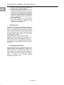
UPS System
Power Modular
Concept
7857.433
7857.434
PMC 12
4,5 and 6kVA
Assembly and Operation Instructions
Microsoft Windows is a registered trademark of Microsoft Corporation.
Acrobat Reader is a registered trademark of Adobe Systems Incorporated.
5.2.
EN
Table of Contents
Start-up in Battery Mode (Cold Start) ......... 18
5.3.
Check Measured Values & Figures detected
by UPS 19
IMPORTANT SAFETY INSTRUCTIONS ..3
5.4.
UPS Default Data and Special Function
Execution...................................................................... 20
1.1.
Documentation Notes ........................................3
1.2.
Retention of Documents...................................3
1.3.
Symbols Used.....................................................3
5.6.
UPS Is Off Due to Unknown Reason and It’s
Trouble Shooting ......................................................... 22
1.4.
Safety Instructions ............................................3
5.7.
Shut Off........................................................... 23
1.5.
Proper Use .........................................................4
5.8.
Maintenance Bypass Mode ............................ 23
1.6.
Storage Instructions..........................................4
6.
TROUBLESHOOTING GUIDE ..... 24
2.
PRODUCT INTRODUCTION ..........5
6.1.
Troubleshooting.............................................. 24
2.1.
General Characteristics ....................................5
2.2.
Special Features.................................................5
7.
BUNDLED SOFTWARE
INSTALLATION GUIDE ......................... 25
3.
UPS FUNCTIONAL DESCRIPTIONS
6
5.5.
UPS Default Settings and their alternatives. 22
7.1.
Hardware Installation.................................... 25
7.2.
Software Installation ...................................... 25
3.1.
UPS Front Panel Display ..................................6
3.1.1.
Symbols on the LCD DisplayPanel............6
8.
OPTIONAL COMMUNICATION
CARD...................................................... 25
3.2.
Rear Panel Descriptions ...................................8
3.2.1.
UPS input and output .................................8
3.2.2.
Battery input...............................................8
8.1.
SNMP Adapter ............................................... 25
8.2.
Internal SNMP Adapter ................................ 26
3.3.
Communication Port Explanation...................9
3.3.1.
EPO (Emergency Power Off).....................9
3.3.2.
RS232 Port Descriptions ............................9
4.
INSTALLATION ............................10
4.1.
Unpacking........................................................10
4.2.
Selecting Installation Position ........................11
9.
HOT SWAPPABLE BATTERY
REPLACEMENT..................................... 27
10.
CUSTOMER SERVICE ................. 27
11.
TECHNICAL DATA ...................... 28
4.3.
Assembling of the different System
Components ..................................................................12
4.3.1.
Tower Assembling steps ..........................12
4.3.2.
Rack installation step................................13
4.4.
Electrical Installation......................................16
5.
OPERATION .................................17
5.1.
Start-Up In Normal Mode ..............................17
2
UPS-Manual
Important Safety Instructions
Important Safety Instructions
1.1. Documentation Notes
The audience for this guide is the technical
specialist familiar with the assembly, installation
and operation of the PMC12 UPS-System.
You should read this operating guide prior to
commissioning and store the guide so it is
readily accessible for subsequent use.
Rittal cannot accept any liability for damage
and operational malfunctions that result from
the non observance of this guide.
1.2. Retention of Documents
This guide and all associated documents are
part of the product. They must be given to the
operator of the unit and must be stored so they
are available when needed.
1.3. Symbols Used
The following safety and other notes are used
in this guide:
Symbol for handling instructions:
•
This bullet point indicates that you should
perform an action.
Safety and other notes:
Danger!
Immediate danger to health and
life!
Warning!
Possible danger for the product
and the environment!
Note!
Useful information
features.
and
special
1.4. Safety Instructions
1. Assembly and installation of the UPS, in
particular for wiring the enclosures with
mains power, may be performed only by
a trained electrician. Other tasks associated with the UPS, such as the assembly and installation of system components with tested standard connectors, and the operation and configuration of the PMC12 UPS-System may be
performed only by instructed personnel.
2. Do not open the case, as there are no
serviceable parts inside. Your warranty
will be void.
3. Do not try to repair the unit yourself;
contact your local supplier or your warranty will be void.
4. If liquids are spilt onto the UPS or foreign objects dropped into the unit, the
warranty will be null and void.
5. Do not install the UPS in an environment with sparks, smoke or gas.
6. This UPS is equipped with an EMI filter.
To prevent potential leakage current
hazard, ensure that the AC main supply
is securely grounded.
7. This UPS is designed to be installed
and commissioned in a sheltered, controlled environment as follows:
- Operating temperature 0-40°C
and 30-90% non-condensing
humidity.
- Always avoid contact with direct
sunlight.
- Do not install the UPS in
inflammable
or
hazardous
environment.
- Dusty, corrosive and salty environments can do damage to any
UPS.
- Install the UPS indoors as it is
not designed for installation outdoors.
8. To prevent any overheating of the UPS,
keep all ventilation openings free from
obstruction, and do not place anything
on top of the UPS. Keep the UPS rear
panel 20 cm away from the wall or other
obstructions.
9. The battery will discharge naturally if the
system is unused for any length of time.
10. Install the UPS away from objects that
give off excessive heat and areas that
are excessively wet.
11. Always switch off the UPS and disconnect the batteries when relocating the
UPS.
12. It should be recharged every 2-3
months if unused. If this is not done,
then the warranty will be null and void.
When installed and being used, the
batteries will be automatically recharged
and kept in top condition.
13. Make sure that the AC main supply
outlet is correctly grounded.
14. Please ensure that the input voltage of
the UPS matches the utility supply voltage. Use a certified input power cable
UPS-Manual
3
EN
Important Safety Instructions
with the correct plugs and sockets for
the appropriate voltage system.
15. Observe the valid regulations for the
electrical installation for the country in
which the unit is installed and operated,
and the national regulations for accident
prevention. Also observe any companyinternal regulations (work, operating and
safety regulations).
16. Use only genuine or recommended
parts and accessories. The use of other
parts can void the liability for any
resulting consequences.
EN
1.5. Proper Use
This UPS is designed for providing power to IT
systems. A use different from that described
here is considered to be an improper use. Rittal
cannot accept any liability for damage resulting
from the improper use or the non-observance
of this guide. The guides for the used
accessories may apply.
Rittal prohibits the use for life-preserving
applications (such as the use in hospitals or the
direct patient care). Rittal expressly does not
sell its products for such applications. Rittal will
not accept any responsibility if a UPS is used in
this area.
1.6. Storage Instructions
For extended storage in moderate climate, the
batteries should be charged for 12 hours at 3
month intervals by connecting the UPS to the
utility supply and switch on input breaker located at UPS rear panel. Repeat this procedure
every 2 months if the storage ambient
temperature is above 30°C.
4
UPS-Manual
Product Introduction
2.2. Special Features
2. Product Introduction
2.1. General Characteristics
The
double-conversion
technology
in
accordance with the specification VFI-SS 111
guarantees the power supply to connected
terminal devices with a pure sinusoidal voltage.
1.
2.
3.
4.
5.
6.
7.
8.
The ultra-efficient PWM technology
achieves a high efficiency for an almost
sinusoidal output voltage. The high crest
factor of the converter filters any switch-on
current peaks without the loading needing
to be modified.
A fully digitalised control circuit provides a
high level of protection and enables future
upgrade. In-built communication capability
enhances its ability for remote control and
monitoring.
The multi-functional LCD/LED panel will
display various status of the UPS. The LED
display may show UPS working status,
Utility Status and UPS Abnormal status,
whilst the LCD display may show
Input/Output Voltage, Frequency, Load
Status, Inner cabinet temperature, and
Abnormal Phenomenon.
To protect the unit from overloading, it
automatically switches to bypass mode in
~160 seconds if loading is at 105% of
rating and in case of overloading of more
than 150% of rating, it switches to bypass
mode immediately. It will automatically
switch back to inverter mode once
overload condition ceases.
If a short-circuit occurs at the output, the
UPS switches the system into standby
operation. The UPS issues an audiovisual
alarm and automatically interrupts the
current output until the short-circuit has
been corrected manually.
Should the unit become overheated, the
internal thermal switch will detect the heat
and switch to bypass mode and vice versa.
Maintenance-free
sealed-type
battery
minimises after-sales service.
The maintenance bypass switch provides
easy and safe troubleshooting or
maintenance function when the utility is
normal.
The transformer-free converter technology with a
housing that can be mounted in a rack or used as
floor-standing enclosure allows the UPS to be
integrated even in environments with restricted
space.
1. The UPS is equipped with an intelligent
microprocessor-based controller and
offers a flexible configuration capability
with
remote
communication
and
comprehensive overload protection.
2. A large 184 V ~ 288 V input voltage
range permits an undervoltage and
overvoltage
correction
without
unnecessary battery discharge and so
ensures an increased battery lifetime.
3. The cold start function ensures that the
UPS can be switched on even when no
mains voltage is present (see chapter
5.2).
4. An optimum battery management
system analyses the charging state of
the battery in order to maximise the
battery lifetime.
5. The "Active Power Factor Correction
(PFC)" control function keeps the "Input
Power Factor (PF)" of the UPS to a
value > 0.99. This allows an excellent
energy efficiency to be attained.
6. Selectable
bypass
input
voltage
tolerance (high/low sensitivity) ensures
that the consumers are not supplied
with undervoltage or overvoltage during
bypass operation. The selectable
voltage ranges are:
(i)
low sensitivity: 184 ~ 260 V
(ii)
high sensitivity: 194 ~260 V.
7. Fixed selectable output voltages
(220/230/240)
to
satisfy
the
requirements for different voltage
systems.
8. The UPS satisfies all relevant EMC
regulations.
UPS-Manual
5
EN
UPS Functional Descriptions
EN
3. UPS Functional Descriptions
of the UPS.
⑫ To re-confirm the change of UPS Setting
3.1. UPS Front Panel Display
3.1.1. Symbols
on
DisplayPanel
Item Symbol
1
LINE
Battery Low
3
Battery Abnormal
4
UPS Overloading
5
UPS Working
Service Mode1
6
A Blackout
Transfer occurred
in UPS Output
the utility input voltage is within the
window; the LED flashes flickeringly to
indicate that the utility input voltage is
within the acceptable window.
8
Green LED lights up to indicate Bypass
10
9
⑤
⑥ UPS Fault or Abnormal
⑦ UPS On/Alarm Silence
⑧ UPS OFF Switch
⑨ Special functions log in/out
⑩ Go to next page
⑪ Go to previous page or change the setting
6
LINE
OFF
UPS Shutoff
UPS Abnormal
Lock
UPS Flow Chart
12
4 Digit
Measurement
Display
13
Indicates the item
desired
to be measured
14
UPS ON Switch or
Alarm Silence
15
UPS OFF Switch
UPS is working under ECO (Economic,
Line-interactive) mode.
OFF
11
Green LED lights up to indicate the UPS
has the capability to run under redundancy
mode.
in
Bypass Input
Abnormal, UPS
fails to transfer to
bypass, Bypass
Abnormal at ECO
mode
Utility Input
Abnormal
② Green LED steadily lights up to indicate that
④
Utility or Bypass
Source
2
① LCD Display
Input is normal.
LCD
Description
7
③
the
1
The specified modes include Normal mode, ECO mode,
CVCF mode, etc..
UPS-Manual
UPS Functional Descriptions
16
Previous Page or
Setting Change
17
Next Page
35
Special Function
Log in /out
Enter or
Reconfirmed
Utility Input Normal
LED
Utility Input Normal
LED
UPS under
Redundancy Mode
UPS under ECO
Mode
18
19
20
21
22
23
36
Er27
37
Er28
38
Er31
39
Er**
CVCF mode with
Bypass input
EN
The UPS must be
operated in normal
mode in parallel
system
Bypass Overload
Time out and cut
off output
The settings of
both control board
and driver board
are not matched
each other
Other Error Code
UPS Fault or
Abnormal Warning
LED
24
25
EPO
26
Er05
27
Er06
28
Er10
Emergency Power
Off
Battery Weak or
Dead
Output Short
Circuit
Inverter Overcurrent
29
Er11
UPS Overheat
30
Er12
UPS Output
Overloading
31
Er15
Wrong Procedure
to Enter
Maintenance Mode
32
Er16
33
Er17
34
Er24
Er21
Output Parameters
Set Error in
Parallel System
ID Numbers are in
conflict in Parallel
System or ID
number Error in
single unit
Parallel
communication
error
(communication
wire disconnected
or failure to find
ID1 UPS ) in
parallel system
UPS-Manual
7
UPS Functional Descriptions
3.2. Rear Panel Descriptions
EN
A B C
E
D
F
H
G
A
B
C
D
E
Terminal Resistor for Parallel function
RS232 Port
EPO Port
Utility Input Breaker
CAN Bus Connection Port for Parallel
System
F External Battery Connector
G Cooling Fan
H Utility Input &UPS Output Power Connector
1 L in
2 N in
PE
3 L out
4 N out
I Customer Options Slot
J Slot
3.2.1. UPS input and output
Model
4,5 kVA
Maximum
Current
24 A
Conductor
Section
4 mm²
6 kVA
32 A
4 mm²
3.2.2. Battery input
8
Model
Maximum
Current
4,5 kVA
25 A
6 kVA
25 A
Conductor
Section
AWG #10,
6 mm²
AWG #10,
6 mm²
UPS-Manual
I
J
UPS Functional Descriptions
3.3. Communication Port Explanation
The Communication port on the UPS provides
true RS232 type communication with the UPS
software to remotely monitor the power and
UPS status.
The bundled UPS software is compatible with
many operating systems such as Windows 98,
& 2000, ME, NT and XP. For other applications
like Novell, NetWare, Unix, Linux, please
contact your local distributor for a proper
solution.
Highest Priority (in descending order),
1)
EPO input port
2)
Optional Interface card
3)
RS232
3.3.1. EPO (Emergency Power Off)
The Pin assignments of the EPO Input port are:
1
2
1 Æ EPO+
2 Æ Ground
To enable the EPO function, please short Pin 1
& 2.
3.3.2. RS232 Port Descriptions
The RS232 interface shall be set as follows:
Baud Rate
Data Length
Stop Bit
Parity
2400 bps
8 bits
1 bit
None
The Pin Assignments of the true RS232 port
are illustrated as follows:
9
8
7
6
UPS-Manual
5
4
3
2
1
Pin 3: RS232 Rx
Pin 2: RS232 Tx
Pin 5: Ground
9
EN
Installation
EN
4. Installation
Warning!
Please thoroughly read the Safety
Instructions (chapter 1.4) before
installing the UPS
4.1. Unpacking
Inspect the delivery conditions of the UPS upon
receipt and notify the freight forwarder and the
dealer in case of any visible damage of the
packing of the product
The packaging is recyclable; save it for reuse
or dispose it properly.
•
•
Remove the UPS from the carton box.
Check the package contents. Standard
contents shall include:
-
1 set of Users Manual
1 set of UPS communication software with
RS232 cable
1 set of accessories pack
-
A1
A2
A3
B1
B2
B3
C1
C2
R1
R2
Include in
Battery Module
S1
10
option
S2
S3
UPS-Manual
S4
Installation
4.2. Selecting Installation Position
0
0
Warning!
The UPS is heavy.
C
40 C EN
0
Select a location sturdy enough to handle the
UPS weight. To ensure proper operation and
long operating life, always position the UPS
according to the following criteria:
Keep minimum 30cm (12 inches) distance
clearance from the rear panel of the UPS to
avoid any obstructions.
Relative Humidly
(non condensing) 30%~90%
Do not block the air-flow to the ventilation
louvers of the unit.
Please ensure the installation site is free from
excessive dust and the ambient temperature
and humidity should be within the specified
limits.
Do not place the UPS in a dusty or corrosive
environment or near any flammable objects.
This UPS is not designed for outdoor use.
30 cm
UPS-Manual
11
Installation
4.3. Assembling of the different
System Components
EN
4.3.1. Tower Assembling steps
Step1: Mounting of Foot Cover and Power
Module
S3
12
UPS-Manual
Installation
Step2: Installation of Power Module and Battery
Module
EN
S3
S1
A3
4.3.2. Rack installation step
Step1: Mounting of Ear Handle
B1 B2 S4
B1 B3 S4
UPS-Manual
13
Installation
EN
Step2: Installation of Ear Cover to Power and Battery Module
S3
S3
Step3: Installation of Rail to Rack
R1
R2
Step4: Installation Battery Module to Rail
14
UPS-Manual
Installation
EN
Step5: Installation Power Module
UPS-Manual
15
Installation
EN
4.4. Electrical Installation
Connect the UPS with the parallel hot swap
chassis (DK 7857.443 or DK 7857.444), the
external bypass (DK 7857.441) or with
installation cable DK 7857.446. Please make
sure, that the parallel hot swap chassis, the
external bypass or the installation cable is
installed correctly. For further information
please read the manual of DK 7857.443 /
DK 7857.444, DK 7857.441 or DK 7857.446.
Danger!
Before starting the installation,
please make sure the grounding is
connected properly.
•
Make sure Utility breaker, UPS’ Utility
breaker is On “Off” position.
Warning!
Make sure the voltage of Utility
matches with the input voltage
window of the UPS.
16
UPS-Manual
Operation
5. Operation
EN
5.1. Start-Up In Normal Mode
•
Connect the Utility to the parallel hot
swap chassis or the installation cable.
Switch on the Power Breaker of the
distribution panel and the breakers of the
UPS’ Utility and Bypass Inputs, and then
the UPS starts up. Green LEDs
&
light up to show the Utility and Bypass
Inputs are normal and the LCD display
with parallel function will illustrate Fig. A1,
Fig. A2 to Fig. B. Otherwise the LCD
display will illustrate from Fig. A2 to Fig.
B.
Fig. C
Then, the UPS is under self-test mode again,
the LCD display will illustrate from Fig. C to
Fig. D and remain approx. 4 seconds under
battery mode, then illustrate from Fig. E1 to
Fig. F if the self-test is successful.
Fig. D: It shows “test”
Fig. A1
Fig. A2
Fig. B
The UPS is on Bypass Mode now and it will
proceed to self-test automatically. If there is
no abnormal message it means the prestartup of the UPS is successful and the
charger starts to charge the batteries.
•
Press the UPS On Switch
for approx.
3 seconds, then the Buzzer sounds twice
and the LCD display changes from Fig. B
to Fig. C.
UPS-Manual
17
Operation
EN
•
Fig. E1: It shows “OK” in self-test
and then the buzzer sounds twice. The
LCD display will illustrate from Fig. A to
Fig. G, and keep awake for approx. 15
seconds.
Press the UPS On Switch
of the UPS
again for about 3 seconds till the LCD
display illustrates from Fig. G to Fig. H,
then the UPS will be in self-test Mode.
The UPS may offer energy to the output
in a minute, and the LCD display
illustrates as Fig. I. In case of failure in
pushing the UPS On Switch in 10
seconds, the UPS will automatically turn
off. You then have to go through step in
this chapter once again.
Fig. E2: It shows “Fail” in self-test
Fig. G: It shows “Off”, which means the UPS
pre-start is successful
Fig. F: It shows “220Vac” in Utility Input
In case of failure in self-test, the LCD display
will illustrate from Fig. D to Fig. E2, then an
error code or error status will be shown on
the screen.
Note!
Your start-up operation of the UPS
is completed. Make sure the UPS
is plugged onto the wall receptacle
for charging at least 8 hours and
the batteries of the UPS are fully
charged.
5.2. Start-up in Battery Mode (Cold
Start)
Fig. H: It shows Utility input is “0” and Utility
Abnormal
Fig. I
Note!
Make sure the UPS you have has
already been installed with at least
1 set (20pcs) of 12V/7Ah or
12V/5Ah batteries.
•
18
once for
Push the UPS On Switch
approx. 5 seconds to awake the UPS,
UPS-Manual
Operation
5.3. Check Measured Values
Figures detected by UPS
&
EN
If you would like to check the measured
values & figures detected by the UPS, please
use scroll down
and scroll up
key
pads. When you use scroll down key pad, the
LCD display will illustrate as Fig. C(Voltage
from Utility Input) ÆFig. I1(Voltage from
Bypass Input) Æ Fig. J(Frequency from
Utility Input) ÆFig. K(Frequency from Bypass
Input) ÆFig. L(UPS Output Voltage) ÆFig.
M(UPS Output Frequency) ÆFig. N(UPS
Output Load %)ÆFig. O(UPS Battery
Voltage) ÆFig. P(UPS Inner Temperature).
Fig. L: It shows UPS output Voltage
Fig. M: It shows UPS output frequency
Fig. I1: It shows voltage comes from Bypass
Input
Fig. N: It shows UPS output load level(%)
Fig. J: frequency from Utility Input
Fig. O: It shows Battery Voltage
Fig. K: It shows frequency from Bypass Input
Fig. P: It shows UPS Inner Temperature
UPS-Manual
19
Operation
5.4. UPS Default Data and Special
Function Execution
EN
•
After the UPS completes start up, press
key pad to change the LCD display
screen to Fig. Q1.
Fig. R2: It shows self-test is “On”
Fig. Q1: It shows buzzer “On”
Fig. S1: It shows Bypass Voltage is adjusted
to narrow tolerance
Fig. Q: It shows buzzer “Off”
•
key pad to scroll down the
Press
screen and check the UPS settings. The
LCD display will subsequently show: Fig.
Q1 (buzzer) Æ Fig. R1 (Self-test) ÆFig.
S1 (Bypass Voltage Windows) Æ Fig. T
(Output
Frequency
Synchronization
Window) ÆFig. U (Inverter Output
Voltage) ÆFig. V1 (UPS Operation
Mode) ÆFig. W (Output Voltage Micro
Tune Value) ÆFig. X (UPS Id) ÆFig. Y
(No. of UPS in Parallel).
Fig. S2: It shows bypass voltage is adjusted
to wider tolerance
Fig. T: It shows Frequency Window is +/-3Hz
Fig. U: It shows inverter output voltage
Fig. R1: It shows self-test is NOT “on”
20
UPS-Manual
Operation
EN
Fig. V1: It shows the UPS is operated in
“normal mode”
Fig. W: It shows Output Voltage Adjustment
% from 0% to 3% or -0% to -3%
Fig. V2: It shows the UPS is operated in “Eco
mode”
Fig. X: It shows UPS Identification Number
Fig. V3: It shows the UPS is operated in
“CVCF 50Hz mode”
Fig. Y: It shows the UPS is the 1st of the
parallel systems
•
Press scroll up key pad to execute
special functions. The functions includes
buzzer ON (as Fig. Q1), or buzzer OFF
(as Fig. Q2, Alarm silence for UPS
Warning) and self-test OFF (As Fig. R1)
or self-test ON. (as Fig. R2. UPS will
execute battery test for 10 seconds. If the
self-test is successful, it will show as Fig.
E1; otherwise, it will show as Fig. E2 &
error message at the same time.)
UPS-Manual
21
Note!
If you want to set a frequency
converter, it must be done by a
qualified technician.
Fig. V4: It shows the UPS is operated in
“CVCF 60Hz mode”
Note!
If you want to set a frequency
converter, it must be done by a
qualified technician.
Operation
5.5. UPS Default Settings and their
alternatives
EN
•
Make sure the UPS is not “On” yet. Press
press “OFF”
key pads for 5 seconds, then
the LCD screen turns to Fig. AA directly,
which means your setting changes are
invalid.
On Switch
and scroll down
key
pads simultaneously for approx. 3
seconds, the buzzer will sound twice, the
LCD display screen shows as Fig. Q1,
then the UPS is under setting mode.
To scroll down the LCD screen, you may
refer to Chapter 5.4.
Fig. Z: Please press Enter key to save data.
Except for Buzzer (as Fig. Q1 & Q2) and
Self-test (as Fig. R1 & R2), all the remaning
default settings may be changed by pressing
scroll up
key pad.
Fig. S1 and S2 show the bypass input
acceptable window, it can be 184 VAC ~ 260
VAC or 195 VAC ~ 260 VAC.
Fig. T shows the bypass frequency window
of the Inverter Output, the acceptable setting
values are ±3 Hz and ±1 Hz.
Fig. U shows the acceptable Inverter Output
Voltage, of which voltage is 200Vac, 208Vac,
220Vac, 230Vac, or 240Vac.
Fig. V1, V2, V3 and V4 show the operation
modes of the UPS, of which the alternatives
are Online, Eco(Economic) mode, fixed 50
Hz Output or fixed 60 Hz Output.
Fig. W shows the adjustments of the Inverter
Output, which may be calibrated as 0%,
+1%, -1%, +2%, -2%, +3%, or -3%.
Fig. X shows a specified address & position
of the UPS when the UPS is in Parallel
mode. The settable numbers are from 1st to
4th.
Fig. Y shows the total number of UPS in
parallel. The settable numbers are from 1 to
4.
Fig. AA: It shows the UPS is locked
•
Your Setting changes are complete.
5.6. UPS Is Off Due to Unknown
Reason
and
It’s
Trouble
Shooting
If there is a serious abnormal condition the
UPS will lock it itself in “OFF” position as
shown in Fig. AA and an abnormal message
will show on the LCD screen
After 3 seconds, all messages will be locked
except Bypass messages(LED
&
LCD
). In cases where the Utility is
abnormal after the UPS is locked, the LED
will be extinguished and the LCD will
be shown on the LCD screen.
To release the UPS lock, please complete
the following:
When all the setting changes are done, you
have to press enter
key Pad to save all
the changes when the LCD screen shows as
Fig. Z, then, the LCD screen will show as Fig.
AA to complete the setting changes. If you
don’t want to change those settings, you may
22
Turn Off the breaker of Utility Input.
UPS-Manual
•
Check those
recorded.
•
Check Chapter 3.1.1 to trouble
shoot the problem of the UPS.
error
messages
Otherwise, consult your
distributor for service.
•
•
•
local
warranty will be void immediately.
EN
Press Off
key pad for 5
seconds and buzzer will sound
twice.
Turn Off the Breaker of Utility
Input.
The UPS lock problem is solved
now, but you should consult with
your Local distributor to make
sure the error message shown is
solved.
•
Release
the
cover
of
the
CAM
Switch(Maintenance Bypass Switch) first,
then turn on the CAM Switch to “Bypass”
mode, and at the right-hand upper Corner of
the LCD screen will show
sign.
•
5.7. Shut Off
•
Press Off
key pad for about 5
seconds, the Inverter output will be
turned off, then the output load is
supplied by Bypass loop and the LCD
screen shows as Fig. B.
• Turn Off the breaker of Utility Input.
The UPS is turned off completely.
5.8. Maintenance Bypass Mode
Note!
A Non-authorised technician is not
allowed to operate the following
procedures. If there is any damage
under unauthorised condition, your
Press the Off
key pad for approx. 5
seconds, the LCD screen shows as Fig.
B and the UPS output is in bypass mode.
Turn off the UPS Utility breaker as well
as the Bypass Input Breaker, you can
now carry out UPS maintenance .
To repeat 1.1, you may put the UPS back to
normal working mode, then turn back the
CAM switch to “INV” mode, fasten back the
cover and repeat 1.1 The UPS will switch
back to inverter mode.
It is required to go through 5.8 first, then go
through 5.8 If you skip 5.8, the UPS will alert
for 10 seconds to warn that the procedure is
abnormal, which may damage the UPS due
to uncertain utility status. The UPS will switch
back to Inverter mode immediately if you turn
the CAM switch back to “INV”.
UPS-Manual
23
Troubleshooting Guide
EN
6. Troubleshooting Guide
6.1. Troubleshooting
When the UPS malfunctions during operation, you may check the following:
a. Is the input and output wiring correct?
b. Is the input voltage of the Utility within the input window of the UPS?
In case of problems or if symptoms still exist, please carry out the following steps. If the problem
persists, please contact your local distributor for help.
Situation
Check Items
Solution
UPS Red Fault LED Check the error code 1.Check to see if the battery connection is
lights up:
shown on the LCD properly done, then re-charge the batteries
for 8 hours to see whether the UPS may
screen
backup normally; otherwise, consult your
local distributor right away.
1.Er05, &
2.Er06, Er10, Er12,
2. Remove some uncritical load at the UPS
Er28 &
output end. If any damage of the coating of
3.EPO
AC power cord, please replace a new one.
4.Er11
5.Er15
3. Remove the short circuit occurred at the
6.Er16, Er27
EPO terminal.
7. Er21
8.Er24
4. Remove the objects blocked on the
9.other error code
ventilation holes.
5. Make sure the UPS is operated normally. If
it is on CVCF mode, you have to turn off and
turn on the UPS again.
6. All of the parameters except ID Number in
the parallel UPS must be same. Please refer
chapter 5.5 to set them again
7. Reconnect the RJ-45 wire or set a UPS
with ID=1.
8. When the UPS is on CVCF mode, it is
prohibited to have bypass input. You have to
turn off the UPS and bypass input and re-start
the UPS.
9. Consult your local distributor for help.
UPS fails to offer
battery backup or its
back up time is shorter
than its calculation.
If the backup time is still too short after 8
hours of charge, please contact your local
distributor for battery replacement.
UPS locks itself and it
can not be turned off.
Please refer to chapter 5.6 to trouble shoot
the problem; otherwise, consult your local
distributor for help.
24
UPS-Manual
7. Bundled Software Installation
Guide
7.1. Hardware Installation
1. Connect the male connector of RS232
cable to the UPS communication port.
2. Connect the female connector of the
RS232 cable to a dedicated RS232 port of
the Computer.
3. For optional interface cards, please refer
to Chapter 8 for more details.
8. Optional Communication Card
EPO
G
DC 36V
The Simple Network Management Protocol
(SNMP)
is
a
worldwide-standardized
communication-protocol. It is used to monitor
any device in the network via simple control
language. The UPS-Management Software
also provides its data in this SNMP format
with its internal software agent. The
operating system you are using must support
the SNMP protocol. We offer our software
with SNMP functionality for Novell, OS/2, all
Windows running on INTEL and ALPHA,
DEC VMS, Apple.
Two types of SNMP interfaces with identical
functionality are available: an external
SNMP-Adapter (Box) and an internal SNMPCard. Both can manage a parallel system (N
modules) and return either global values which are consistent for the whole parallel
system - or specific values from the single
modules.
EN
UPS
External SNMP-Adapter
9
Ethernet
1
2
AC OUTPUT
Internal SNMP-Card
8.1. SNMP Adapter
7.2.
Software Installation
Please install the Software which is on the
enclosed CD or visit our website
www.rimatrix5.com and for download from
UPS software
http://www.rimatrix5.com/service_support/do
wnloads.asp
The adapter may be configured via Telnet,
HTTP (Web-Browser) or serial connection
(Terminal). For normal operation at least one
network connection (Ethernet) is required.
The SNMP adapter can be used, utilising the
RCCMD send function, for an automatic network wide shut down or just for informing
connected users. The shut down procedure
can be initiated on a low residual battery
autonomy time (downtime) or by a
countdown timer which is started at the
beginning of the alarm. A shut down is
therefore possible without extra input from
the operator, and is fully software controlled.
UPS-Manual
25
Optional Communication Card
shut down possible without additional SNMP
management software.
8.2. Internal SNMP Adapter
EN
The Internal SNMP-Card can be inserted into
the appropriate slot of the PMC12. This
adapter communicates via the serial port of
the UPS and makes a direct multiple server
26
For detailed information please see Software
Manual provided with the PMC-Software CD
ROM. RCCMD - Remote Console Command
module for a multi-server shutdown. This
stand-alone software module is designed to
receive and execute a command issued by a
remote device. Thanks to RCCMD it is
possible to execute a shutdown in an
heterogeneous multiplatform network. The
new release RCCMD 2 is an application
available for all Operating Systems,
analogous to PMC-Software. Our SNMP
Interfaces are compatible to RCCMD.
UPS-Manual
Hot Swappable Battery Replacement
9. Hot Swappable Battery Replacement
1. Unscrew the flange of the battery bank
front panel as indicated in Step 1.
4. Unplug the hot swappable
connectors as shown in Step 4.
2. Remove the front panel as indicated in
Step 2.
5. Remove the battery packs from the
battery bank as shown in Step 5.
battery
3. Remove the screw of the battery pack as
shown in Step 3.
10.
Customer Service
If you have any technical questions or questions
concerning our product spectrum, contact the
following service address:
Tel.: +49 (0)2772/505-1855
http://www.rimatrix5.com
E-mail: [email protected]
UPS-Manual
27
EN
Technical Data
EN
11.
Technical Data
Model
4,5 kVA
6 kVA
INPUT
Voltage Window
160~280 VAC*
Frequency
45 ~ 65 Hz
Phase/Wire
Single, Line + Neutral + Ground
Power Factor
Up to 0.99 at 100% Linear Load
Current THD
<6% at 100% Linear Load
OUTPUT
Voltage Window
220/230/240 VAC Selectable
Voltage Adjustment
0%; ±1%; ±2%; ±3%
Voltage Regulation
±2%
Capacity
4500 VA / 3600 W
Rated Power Factor
Wave Form
6000 VA / 4800 W
0.8 Lagging
Sine Wave, THD<3%(no load to full Linear load)
Frequency Stability
±0.2%(Free Running)
Frequency Regulation
±1%; ±3%
Transfer Time
0ms
Efficiency(AC to AC, Normal)
Up to 90%
Efficiency(AC to AC, ECO)
Up to 97%
Autonomy at load
50%
100%
50%
100%
1 Battery
20 Min.
9 Min.
18 Min.
8 Min.
2 Batteries
48 Min.
23 Min.
45 Min.
20 Min.
3 Batteries
95 Min.
39 Min.
74 Min.
33 Min.
DC Start
Yes
BATTERY
Type
Sealed Lead Acid Maintenance Free
12 V / 7 Ah
Quantity
20 pcs
Voltage
240 VDC
Recharge Time
28
4 hours to 90%
UPS-Manual
Technical Data
DISPLAY
EN
Status On LED + LCD
Line Mode, Backup Mode, ECO Mode, Bypass Supply,
Battery Low, Battery Bad/Disconnect, Overload,
Transferring with interruption & UPS Fault.
Readings on LCD
Input Voltage, Input Frequency, Output Voltage, Output
Frequency, Load Percentage, Battery Voltage & Inner
Temperature.
Self-Diagnostics
Upon Power-on, Front Panel Setting & Software
Control, 24-hour routine checking
ALARMS
Audible and Visual
Line Failure, Battery Low, Transfer to Bypass, System
Fault Conditions
PHYSICAL
Dimensions (WxDxH) mm
440x88x660 (UPS Module)
Input/Output Connection
Hardwire
External Battery Connection
Plug & Play
Net Weight (Kgs)
24 (UPS Module)
BATTERY BANK DIMENSIONS Convertible (Rack / Tower)
7857.442 (20pcs 12V/7Ah)
440x133x660(3U)
BATTERY BANK NET WEIGHT
7857.442 w/o bat. / with bat.
18 kg/ 68 kgs
ENVIRONMENT
Operating Temperature
Temperature Warning
0° C to 40° C
The battery design life is based on a temperature of 25°
C. Ambient temperature above this range will reduce
battery life.
Altitude
0~2000 m up to 40° C,
3000 m up to 35° C
Humidity
90% RH Maximum, Non-Condensing
Noise
<50 dB (at 1 meter)
COMPUTER INTERFACE
Interface Type
Standard RS232 Interface, EPO
Communication Slots
SNMP / WEB Card
UPS-Manual
29
EN
SAFETY CONFORMANCE
Quality Assurance
ISO9001 Certified Company
Safety Standard
EMC Standard
EN62040-1, UL1778
EN62040-2, EN61000-3-2, EN61000-3-3,
FCC Class A
Marks
CE, WEEE
* (160~176Vac at <75% load)
30
UPS-Manual
04/11 – A38862 04 IT74
Rittal GmbH & Co. KG · Postfach 1662 · D-35726 Herborn
Telefon +49(0)2772 505-0 · Telefax +49(0)2772 505-2319 · eMail: [email protected] · www.rittal.de