1
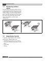
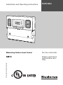
Installation and Operating Instructions
mode
Controller
°F
72186100-00N
For the contractor
AM10
Please read these
instructions carefully
7218 6100 (07/2010) US/CA
Modulating Outdoor Reset Control
US-listed
Contents
Contents
1
Installation manual . . . . . . . . . . . . . . . . . . . . . 3
1.1
Description of Module . . . . . . . . . . . . . . . . 3
1.2
Outdoor reset . . . . . . . . . . . . . . . . . . . . . . . 4
1.3
Mounting of the AM10 . . . . . . . . . . . . . . . . 4
1.4
Positioning outdoor sensor . . . . . . . . . . . . 6
1.5
Single Boiler Control . . . . . . . . . . . . . . . . . 6
1.6
Cascade Boiler Control . . . . . . . . . . . . . . . 8
2
User Manual . . . . . . . . . . . . . . . . . . . . . . . . . . . . 9
2.1
Introduction . . . . . . . . . . . . . . . . . . . . . . . . . 9
2.2
Heating curve . . . . . . . . . . . . . . . . . . . . . . . 9
2.3
Operation . . . . . . . . . . . . . . . . . . . . . . . . . . 9
2.4
Settings description . . . . . . . . . . . . . . . . 10
2.4.1 1st menu, idle display . . . . . . . . . . . . . . . 10
2.4.2 2nd menu, supply temperature set point. 10
2.4.3 3th menu, target point of heating curves. 10
2.4.4 4th menu, base point of heating curves 11
2.4.5 5th menu, warm weather shut down . . . 11
2.5
Faults . . . . . . . . . . . . . . . . . . . . . . . . . . . . 11
2.5.1 Fault code 5H . . . . . . . . . . . . . . . . . . . . . 12
2.5.2 Sensor fault/emergency operation . . . . 12
Notes . . . . . . . . . . . . . . . . . . . . . . . . . . . . . . . . . . . . 13
2
AM10 - We reserve the right to make any changes due to technical modifications!
Installation manual
1
Installation manual
1.1
Description of Module
1
Product description
The AM10 is a modulating control for
Buderus boilers equipped with the EMS
bus. It sets the supply water temperature
based on outdoor temperature. The boiler
fires, runs and modulates based on the
information received from the AM10, and
the delta temperature between supply and
return.
An ON/OFF signal from 3th party room
thermostats or zone controllers is used to
communicate a heat demand.
The AM10 offers warm weather shutdown
when the outdoor temperature rises above
an adjustabletemperature. To control and
stage multiple boilers, combine the AM10
with an MCM10 module.
mode
°F
2x
4x
2x
3x
2x
72186100-01N
Fig. 1
Included items
AM10 - We reserve the right to make any changes due to technical modifications!
3
1
1.2
Installation manual
Outdoor reset
1.3
Outdoor reset is a smart way to
economically control space heating based
on outdoor temperature. It functions based
on the fact that the colder the weather the
greater the heat loss of a structure, and the
higher the supply water temperature
needed to heat the house. On a warmer
day with smaller losses a lower water
temperature will be able to heat the house.
Mounting of the AM10
Mount the AM10 module inside a Buderus
boiler. For detailed instructions see the
installation manual of your boiler.
For connecting the AM10 to the EMS-Bus:
(Æfig. 5).
Outdoor reset is the preferred control
when using multiple zones, as the boiler
supply water temperature is not dictated by
a master or largest zone, but solely based
on the heat loss of the structure.
Heating curve
The AM10 has a built in linear heating
curve that sets the supply water
temperature in relation to the outdoor
temperature.
The maximum supply water temperature is
set on the boiler dial works as a high limit.
The boiler will follow the heating curve in
the AM10 up to the high limit.
Setting
Default
Example 1
Example 2
Example 3
Outside
Supply
temperature temperature
[°F]
[°F]
14
167
0
170
-10
175
-20
180
Tab. 1 Heating curve
4
AM10 - We reserve the right to make any changes due to technical modifications!
Installation manual
1
On/Off
Ø
°F
mode
L
Ø = 18 AWG
L ≤ 100 ft.
R ≤ 100 Ω
72186100-02N
Fig. 2
Thermostat
mode
Ø
°F
L
Ø = 18 AWG
L ≤ 100 ft.
R ≤ 100 Ω
72186100-03N
Fig. 3
Outdoor sensor
[°F]
[k Ω]
[°F]
[k Ω]
[°F]
[k Ω]
[°F]
[k Ω]
-40
336.5
5
72.9
50
19.9
95
6.5
-31
242.6
14
55.3
59
15.7
104
5.3
-22
177.0
23
42.3
68
12.5
113
4.4
-13
130.4
32
32.7
77
10.0
122
3.6
-4
97.1
41
25.4
86
8.1
Tab. 2 Sensor resistance table
AM10 - We reserve the right to make any changes due to technical modifications!
5
1
1.4
Installation manual
Positioning outdoor
sensor
For best performance the outdoor sensor
is to be positioned where the sun can never
reach it. Mount only on a north facing wall
of the building, out of the sunlight, with at
least 1 foot (30 cm) above snow line. Keep
the sensor away from heat sources like
dryer, water heater, or boiler vents,
windows, etc.
☺
☺
Fig. 4
Sensor location
1.5
Single Boiler Control
72186100-04N
To equip a single Buderus with outdoor
reset control, required items are:
• ON/OFF thermostat for every heating
zone with individual zone pump or zone
valve
• Pump relay
• Wiring
6
AM10 - We reserve the right to make any changes due to technical modifications!
Installation manual
1
AM10 Module
Wire terminal strip
RC 10/20
Outdoor
sensor
T T
Connection
DHW
Sensor
Safety
Limit
Orange
Blue
Lt Green
Lt Gray
Red
RC
FA
WA
FW
1
2
1
2
1
2
1
Outdoor
sensor
EV
2
1
2
Terminals FA and WA
not used in this
application
1
Factory
Installed
Jumper
2
On / Off
1
2
1
2
DHW Tank
Sensor
Zone
valve
Low Voltage
Field wiring
120 VAC
Field wiring
T
T
X
X
Pump Relay
N
H
C1
C2
Neutral
Line
Dedicated
120 VAC
15 Amp Circuit
Fig. 5
72186100-05N
Wiring detail
If there are multiple zones, wire all
thermostats in parallel for calls for heat
from any thermostat to produce a heat
demand.
Do not install RC10 module
when using this configuration.
AM10 - We reserve the right to make any changes due to technical modifications!
7
1
1.6
Installation manual
Cascade Boiler Control
In a Buderus cascade with an MCM10 the
AM10 is used as a modulating control
based on outdoor temperature. The
MCM10 will determine which boiler or
boilers need to fire and at what modulation.
The MCM10 also rotates the boilers for
equal run time. For details on the MCM10
module, consult the MCM10 manual.
Do not install RC10 module
when using this configuration.
8
AM10 - We reserve the right to make any changes due to technical modifications!
User Manual
2
User Manual
2.1
Introduction
2
The AM10 is an outdoor temperaturedependent controller with a linear heating
curve. The heat demand is communicated
using a dry contact input.
2.2
A
C
1
B
Heating curve
The heating curve indicates the
relationship between the outdoor
temperature and the supply temperature.
This concerns a straight line which can be
described by 2 points (A and B). Point A is
the supply temperature at an outdoor
temperature of 14 °F and point B is the
supply temperature at an outdoor
temperature of 68 °F. C is the high limit
supply temperature set on the boiler
(Æfig. 6).
The supply temperature requested by the
AM10 can never be higher than the high
limit supply temperature of the boiler. For
this reason it is recommended to set the
supply temperature on the boiler (line C) to
the maximum value, unless you deliberately
want to compensate the heating curve, for
example for a radiant floor heating system.
+68
+14
2
Fig. 6
1
2
-40
72186100-07N
Heating curve
Supply temperature [ °F]
Outdoor temperature [ °F]
2.3
Operation
Use the Mode key (Æ fig. 7, [1]) to go
through the various menu items(Æ fig. 7,
[4]) ; a line (Æ fig. 7, [2]) on the display
indicates the active menu item.
The value of a menu item which can be set
will flash. The value can then be changed
using the plus + and minus – (Æ fig. 7,
[3]) keys. The settings will not be lost if
there is a power outage.
2
1
3
4
°F
mode
72186100-08N
Fig. 7
Display view
AM10 - We reserve the right to make any changes due to technical modifications!
9
User Manual
2
If the display receives no user's input for
10 seconds, it will automatically switch
over to its idle display (outdoor
temperature). The display code is shown
(flashing) when the appliance is locked.
Otherwise the following symbols are
implemented:
Symbol
Icon
2nd menu, supply temperature
set point
Use the Mode key to select the 2nd menu
item: the supply temperature setpoint
.
2.4.2
Range: 32 - 194 °F.
Meaning
Flame
Appliance in
heating mode
Switch
contact
AM10 received a
heat demand
Engineer‘s
wrench
Appliance locked
°F
72186100-10N
Supply temperature on the boiler
3rd menu, target point of
heating curve
Use the Mode key to select the
symbol. This concerns the target point of
the heating curve corresponding with an
outdoor temperature of 14 °F. The value
will flash and can be changed using the +
and – keys.
Adjustment range: 68 - 194 °F.
Factory setting: 167 °F.
2.4.3
Tab. 3 Mode key icons
2.4
Fig. 9
Settings description
2.4.1 1st menu, idle display
The current outdoor temperature is shown
(64 °F); the corresponding symbol
is
marked. A heat demand
has been
registered on the AM10; the appliance is in
heating mode .
°F
°F
72186100-09N
72186100-11N
Fig. 8
10
Idle display
Fig. 10 Target point of heating curve
AM10 - We reserve the right to make any changes due to technical modifications!
User Manual
2
4th menu, base point of
heating curve
Use the Mode key used to select the
symbol. This concerns the base point of the
heating curve corresponding with an
outdoor temperature of 68 °F. The value
will flash and can be changed using the
plus + and minus – keys.
2.4.4
Adjustment range: 68 - 194 °F.
Factory setting: 86 °F.
°F
72186100-13N
Fig. 12 Display of
2.5
°F
72186100-12N
th
Fig. 11 Display of 4 menu item
5th menu, warm weather shut
down
Use the Mode key to select the warm
weather shut down temperature
. This
concerns the maximum outdoor
temperature at which the heating is still
operational. The value will flash and can be
changed using the plus + and minus –
keys.
2.4.5
5th
menu item
Faults
The appliance is locked. When the
appliance is in idle mode, a flashing
appliance display code is shown instead of
the outdoor temperature and the key
symbol
is displayed. Adjustments can
still be made by selecting the relevant
parameter using the Mode key. However,
the appliance will be in idle mode and the
display code will show for as long as the
system detects a fault.
The meanings of the various codes and the
relevant troubleshooting procedures are
detailed in the boiler's installation
instructions.
Adjustment range: 32 - 86 °F.
Factory setting: 70 °F.
AM10 - We reserve the right to make any changes due to technical modifications!
11
2
User Manual
2.5.1 Fault code 5H
This is a communication fault. Check the
connection to the boiler.
°C
72186100-14N
Fig. 13 Fault indication
2.5.2
Sensor fault/emergency
operation
If no sensor is detected on the AM10,
dashes are shown in the numerical field
instead of the outdoor temperature.
If there is a heat request (the display will
show
), the AM10 will request 122 °F,
if this is permitted by the high limit.
°F
72186100-15N
Fig. 14 Sensor fault display
12
AM10 - We reserve the right to make any changes due to technical modifications!
2
Notes
AM10 - We reserve the right to make any changes due to technical modifications!
13
2
Notes
14
AM10 - We reserve the right to make any changes due to technical modifications!
2
Notes
AM10 - We reserve the right to make any changes due to technical modifications!
15
United States and Canada
Bosch Thermotechnology Corp.
50 Wentworth Avenue
Londonderry, NH 03053
Tel. 603-552-1100
Fax 603-584-1681
www.buderus.us
U.S.A.
Products manufactured by
Bosch Thermotechnik GmbH
Sophienstrasse 30-32
D-35576 Wetzlar
www.buderus.com
Bosch Thermotechnology Corp. reserves the right
to make changes without notice due to continuing
engineering and technological advances.