1
PS Engineering
PMA7000M-S Series Audio Selector Panel and Intercom System
Installation and Operator’s Manual for Civil Air Patrol
Section III OPERATION
GENERAL INFORMATION
3.1
SCOPE
This section provides detailed operating instructions for the PS Engineering PMA7000M-S, and
PMA7000S Audio Selector Panel/Intercom Systems, CAP versions. Please read it carefully
before using the equipment so that you can take full advantage of its capabilities.
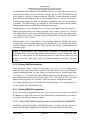
This section is divided into four sections covering the basic operating areas of the PMA7000MS systems. They are Audio Selector, Transceiver Selection, Intercom, and Marker Beacon
Receiver (7000M-S only).
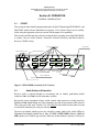
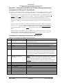
Receive Audio Selectors
Marker Mode Selector
Marker Indicator Lamps
O M
Mic Selector
Photo
Detector
Com 1
I
High
Low
Com 1
Nav 1
MKR
ADF
DME
Test
V
o
l
u
m
e
Com 2
Iso
Nav 2
ICS
Com3
Com 2
Com 1/2
Com 1/3
Com 3
Com 2/3
Transmit
Swap
SPR
All
Push
(Fail-Safe)
Crew
ENGINEERING
INCORPORATED
R
Mounting
Screw
PMA7000M-S
Crew ICS/
Music 1 Mute
Speaker Switch
TX Indicator
Intercom Mode Sel.
Swap Indicator
Intercom Vol.
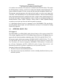
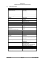
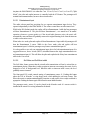
Figure 3-1 PMA7000M-S controls (CAP Version)
3.2
Audio Selector (All models)
Receiver audio is selected through two momentary and six latched, push-button, backlit
switches. Com 1 and Com 2 are the momentary switches.
Because the rotary microphone selector switch controls what transceiver is being heard, the
Com l and Com 2 push-buttons are of the momentary type and do not remain in when selected.
This is also part of the "auto” function. You will always hear the audio from the transceiver that
is selected for transmit by the rotary mic selector switch.
The users can identify which receivers are selected by noting which of the switch LEDs are
illuminated. Push buttons labeled Nav 1, Nav 2, COM 3, DME, MKR (Marker), ADF and
SPR (Speaker) are "latched" type switches. When one of these buttons is pressed, it will stay in
200-072-0004
Page 3-1
Rev. 4, Sept. 2000