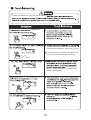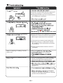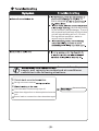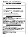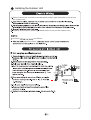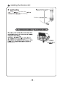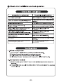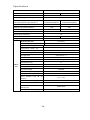
1
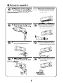
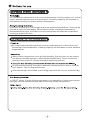
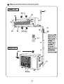
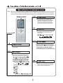
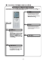
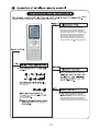
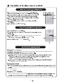
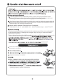
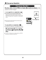
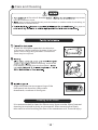
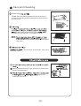
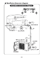
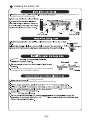
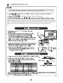
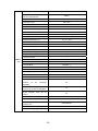
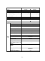
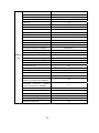
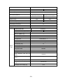
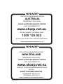
Split Type Inverter Room Air Conditioner
OPERATION MANUAL
MODELS
AY-X09LCJ
AY-X12LCJ
AY-X18LCJ
AE-X09LCJ
AE-X12LCJ
AE-X18LCJ
Thank you for choosing a SHARP air conditioner. Please read this manual
thoroughly before using your air conditioner and keep it for future
reference.
and cleaning
ing
ing
Specifications
NOTE: The figures in this manual may be different to the actual product.
that should be prevented.
that
Collection of such waste should be separated for special
treatment as required by local regulations.
, pl ease ref er the mat ter to
a qualified air conditioner contractor.
objects
Don’t exp ose you rsel f to col d output
ai r for prol onged periods as it may
aff ect you r physi cal con di tion.
To change the airflow direction,
adjust the vertical and lateral
air flow direction by using the
remote control.
Don’t expose animals and
plants directly to the output
air flow as it may have a
detrimental effect on them.
This air conditioner is designed
for normal residential use. Do not
use for any other purpose such as
food preservation or drying clothes.
Don't place a space heater or
cooking appliances near the
air conditioner.
Air conditioners absorb heat in the room and transmits it to the outdoor unit, so that
indoor ambient temperatures are decreased. Its cooling capacity will increase or
decrease according to outdoor ambient temperature.
If the unit is running in COOL mode and in low ambient temperature, frost may be
formed on the heat exchanger. When indoor heater exchanger temperature
decreases below zero, the indoor unit microcomputer will stop the compressor
running to protect the unit.
Air conditioners absorb heat from outdoors and transmit it to the indoor unit,
increasing room temperature. Heating capacity will decrease in lower ambient
temperatures.
Wh en outdoor temp erature is low but high humi dity, frost ma y form on the outdoor
unit during extended operation, affecting heating efficiency. The air conditioner
operation ma y stop for 8-10mi ns during auto defrosting function.
During auto defrosting, the indoor indicator flashes and the outdoor unit may
emit vapour. This is not a malfunction.
After defrosting has finished, the heating operation will recover automatically.
In "HEAT" mode, if in the following situations, the operation of indoor unit maybe
delayed until the heat exchanger has achieved a certain temperature.
Na me and function of each part
Note: Be sure that there are no obstructions between receiver and remote control;
Don't drop or throw the remote control; Don't spill any liquid on the remote
control; Don't leave remote control directly in sunlight or hot environments.
Pres s this button to turn Sleep mode on or
off. Sleep mode "off" is defau lt when
switched on. Sleep functi on is cancelled
when unit is switched off. Sleep mode
durati on can be adjusted . Sleep mode is
not avail able under Fan and Auto modes.
Press this button to select between Auto,
Low, Middle and High speed fan settings.
Auto fan speed is default when unit
switched on.
AUTO
Press this button to turn unit on or off.
Sleep function will be cancelled if unit
is turned off.
Press this button to set clock function.
the clock symbol will blink and display.
Within 5 seconds, the time can be adjusted
by pressing + or - button. Press button
continuously for rapid time change.
During blinking, press confirm button or
clock button again to complete time setting.
Press this button to select between Auto,
Cool, Dry, Fan and Heat modes. Auto
mode is the default when switched on.
Press this button to select between:
setting desired temperature, display
indoor ambient temperature, display
outdoor ambient temperature.
Name and function of wireless remote control
Some
buttons on this control are not applicable to this unit.
Preset temperature is increased by
pressing this button. Continuously
pressing and holding for 2 seconds
changes the temperature rapidly.
Preset temperature is decreased by
pressing this button. Continuously
pressing and holding for 2 seconds
changes the temperature rapidly. The
temperature adjustment is unavailable
under the Auto Mode.
Press this button to select or cancel Blow
mo de. Blow 'off' is default wh en unit is
swi tched on.
Pres s this button to turn light On or Off.
Light On is defau lt when unit is switched on.
Under Co ol or He at mo de, pressing this
button turns on or off the Turbo function.
After the turbo function is turned on, the
Turbo signal is displayed.
Some
buttons on this control are not applicable to this unit.
Press this button to select Timer On
setting. Pressing the + or - button
during the first 5 seconds adjusts the
time value by one minute each time
pressed. Holding the + or - button down
for more than 2 seconds changes the
time rapidly. While time is blinking,
press Timer On button to confirm
setting. After setting, repressing the
Timer On button cancels the operation.
sel ect
The functions below are not applicable
to this model.
When the "I FEEL"
symbol is displayed the remote control
will send a temperature reading to the
wall unit every 10 mi nutes. Press the
“I FEEL" button again to cancel operation.
di rect ions
Press On /Off button to start or stop operation.
to switch On or Off the display on the main unit.
m odels
to switch
BLOW
the fan will con tinu e to bl ow af ter the un it is stop pe d to rem ove
BLOW
BLOW
BLOW
the BLOW function is not operated.
senses the room temperature automatically to select a suitable running method
for room comfort.
TURBO
W hen TURBO mode is selected
To set the guide louvre to a desired position, press Swing Up and Down button
continuously for more than 2 seconds and hold until desired position is achieved.
Releasing the button now stops the swinging at the desired position.
After Swing Up and Down mode is switched on, pressing the button again within 2
seconds circulates between the various settings. If button is pressed more than 2
seconds later, the function is switched off.
About switch between Fahrenheit and Centigrade
。
。
Under status of unit off, press MODE and - buttons simultaneously to switch C and F .
If Defrost function has been selected, it will continue even if the unit is switched off
by the remote control. If settings are changed, they will only be carried out after
defrosting is finished.
To turn defrost function On or Off press Mode button and Blow button simultaneously
when remote control is powered off. When
i s selected,
pressing
switched off.
R emove the battery cover plate from the rear of the remote control.
(As shown in the figure).
Replace the battery cover plate.
remove batteries to prevent damage from leaking batteries.
does
the batteries out and replace them after 30 seconds. If still not
operating properly, replace the batteries.
on the
main unit. Operation will be in Auto Run mode and the temperature setting or fan
speed cannot be changed.
To operate: Press the AUTO/STOP button and
the unit will enter into AUTO RUN mode.
The microcomputer will monitor the room
temperature to select the (COOL, HEAT, FAN)
mode automatically, to obtain the comfortable
effect.
To turn off: Press the AUTO/STOP button
to switch the unit off.
To operate: Adjust the code switch to AUTO
and the unit will enter into AUTO RUN mode.
monitor
To turn off: Adjust the code switch to STOP
position to switch the unit off.
Care and Cleaning
to prevent
at the circuit breaker
the risk of electric shock.
pour or spray liquids directly onto the indoor or outdoor units for cleaning, to
prevent risk of electric shock.
Only wipe the
Rotate the front panel upwards in the direction
of the arrow. While holding both sides of the front
panel, remove by pulling forwards. Some minor
force may be required.
Before cleaning, remove the
LCD display (if fitted) from the front panel.
Align and insert the two support lugs of the
front panel into the slots, then rotate
downwards, as shown in the figure.
Cleaning the air filters
It is recommended to clean the filters every three months. More frequent
cleaning is required in dusty environments. After removing the filters,
take care to avoid touching the fins of the condenser unit, to avoid injury.
Care and Cleaning
Removing
Rotate the front panel upwards in the direction of
the arrow. Pull the air filter downwards and remove
from the unit.
water temperature should be
and leave to dry naturally in a shady location.
Never dry
it with a heater or open flame, as fire or deformation
may occur.
in the di rec tion of the ar rows, then cl os e
the front panel.
Never operate the unit if the wiring or connections
have been damaged.
report to a
licenced contractor.
The air conditioner is not user serviceable.
if attempt to
If a bad smell has been accumulated
from the environment, clean the air filter.
If smells persist, contact your Approved
Service Centre to arrange cleaning.
fluid gurgling
noises. This is not a fault - it is the sound
of flowi ng refrigerant.
mist
mi st
cracking sound
a nd/or contraction
will
Has the circuit breaker device tripped off?
Have the wiring or connections been
damaged?Please report to an authorised
air conditioner contractor.
Is the fan
other
working
Check that there is no magnetic or electrical
interference near the main unit that may be
affecting the operation of the controller.
Is the wireless remote control within its
operating range, or obstructed? Check
the condition of the batteries and replace
if necessary.
Check if the wireless remote control is
damaged.
Water is dripping or leaking from the
indoor unit
has overflowe d.
has been loosened.
Water is dripping or leaking from the
outdoor unit
water condensation occurs naturally
around the pipe and connections.
some ice has thawed and flowed out.
some
water adhered on the heat exchanger has
dripped out.
F
stopped,
there is a sound of refrigerant flowing
in the reverse direction.
air
flow is stopped
fros t can be for med
on the outdoor heat exchanger. The unit
will automatically defrost and the indoor
unit will stop blowing air for 3-12 mins.
During defrost operation, water or
vapour may be emitted.
,disco nnect from the power
supply, and report to an authorised air conditioner
contractor in the following situations.
St rong odours are emi tted
Circuit breaker continuously trips off.
Water has dripped into or been splashed onto the
unit.
Power leads or connections have been damaged.
power supply.
d iscon ne ct from
The unit mus t only be installed by authorised air conditioner contractors according to mun icipal
or governmen t regulations and in compl iance wi th this man ual.
The unit should be installed with a dedicated electrical circuit, and a circuit breaker should
be fitted in accordance with regulations.
Proper installation position is vital for correct and efficient operation. Avoid the
following positions:
liquids
electro-magnetic
Where salt-laden air is a problem (such as close to coastal areas).
Where the air is contaminated with industrial vapours and oils.
Where the air contains sulphured gas such as in hot spring zones.
environments where corrosion or air quality is a problem.
away from any obstruction. Ensure the air can be
blown through the whole room.
where it is
easily connected to the outdoor unit.
the wall
1.8m above the floor.
is installed in accord with the installation instructions.
which will
is installed in accord with the installation instructions,
and is convenient for maintenance and repair.
between indoor and outdoor units is within 5 metres, and the length
of the connecting tubing does not exceed 10 metres.
which
pedestrian
A dedicated power supply circuit should be used, in accordance with local electrical
safety regulations.
The product should be installed by a licenced air conditioning contractor in accordance
with AS/NZS3000 and your electrical supplier's rules.
A circuit breaker should be installed.
WARNING: inadequate or incorrect electrical connections may cause electrocution or
fire.
. P lease ensure the the unit is reliably earthed.
the air conditioner is the earthing wire, and cannot be
used for any other purpose. Improper earthing may cause electrocution.
The unit must be reliably earthed in accordance with AS/NZS3000.
AS/NZS3000 and your electrical
supplier's rules.
Approved
Service Centre
Gap
Gap
Gap
180
Gap
G
ap
Gap
Height
Gap
G
ap
Gap
Installing the indoor unit
is at the lef t, the righ t si de sh ou ld
be slightly higher to allow drainage.
Spirit Level
gap
gap
proper
Drainage hoses passing through indoor areas should
be wrapped with insulation material.
by rotating upwards.
Remove the electrical connection cover plate and screw.
hole in the
provided
using
Replace
. U sing
replace the
Installing the indoor unit
All interconnecting wiring between indoor and outdoor unit must be performed by
a licenced electrical contractor in accordance with AS/NZS3000.
the
unit to
screws adequately to prevent loosening.
Ensure the electrical connections are properly earthed to prevent electrical shocks.
Ensure all wiring connections are secure and the cover plates are reinstalled properly.
Poor installations that allow dust or moisture incursion may cause fire or electrocution.
A circuit breaker of adequate capacity should be installed at the switchboard.
output
Nm
ensure the joint nut is adequately
tightened,
Installing the Outdoor Unit
Remove electrical connection access plate (either right hand side or front) from
the outdoor unit.
Replace access plate (either right hand side or front) on the outdoor unit.
Incorrect
unit failure.
has been fitted,
Installing the Outdoor Unit
soapy
gas detection
are leaking.
Outdoor
attach
satisfactorily.
satisfactory
to the product.
product.
Are the inlet and outlet air openings
blocked?
Is the quantity of gas charge sufficient
for the length of pipe run?
may be
insufficient.
Specifications
Model
AY-X09LCJ;AE-X09LCJ
Function
COOLING
HEATING
Rated Voltage
220-240V
Frequency(Hz) (High/Standard *)
50HZ
Total Capacity (W) (High/Standard *):
3300/2600/ 1188(W)
3800/2850/1109 (W)
11200/9000/4063(Btu/h)
13000/9800/3792(Btu/h)
Power Input (W) (High/ Standard*)
1200/600/264
1250/650/230
Rated Input (W) (High/ Standard *)
1200
1250
5.5
6.0
Total Capacity (Btu/h) (High/ Standard *):
Rated Current (A) (High/ Standard *)
Air Flow Volume (m /h) (H/M/L)**
450
Dehumidifying Volume (l/h)
0.8
3
EER / C.O.P (W/W)
4.25
4.22
Energy Class
A/A
AY-X09LCJ
Model of Indoor Unit
Fan Motor Speed (r/min) (SH/M/L)
1350/1100 /950l/820
Output of Fan Motor (w)
Input Power of
Heater
10
(w)
/
Fan Motor Capacitor (uF)
/
Fan Motor RLA(A)
/
Fan Type-Piece
Cross flow fan – 1
Diameter-Length (mm)
φ85 X 668
Evaporator
Aluminum fin-copper tube
Pipe Diameter (mm)
Indoor
unit
φ7
Row-Fin Gap(mm)
2-1.5
Coil length (l) x height (H) x coil width (L)
657X285X25.4
Swing Motor Model
MP28VB
Output of Swing Motor (W)
2
Fuse (A)
Sound
PCB 3.15A
Pressure
Level
dB
(A)
(S/H/M/L)
Sound Power Level dB (A) (S/H/M/L)
Dimension (W/D/H)( mm)
Dimension
of
Transformer 0.2A
42/ 38 / 30/28
53/ 47/ 40/38
872X178X283
Package
(W/D/H)( mm)
Net Weight /Gross Weight (kg)
935x260X375
12/15
- 24 -
AE-X09LCJ
Model of Outdoor Unit
Compressor
SANYO
Manufacturer/trademark
Compressor Model
C-6RZ110H1A
Compressor Type
Twin rotory
L.R.A. (A)
33
Compressor RLA(A)
4.59
Compressor Power Input(W)
800
Overload Protector
Int11l-3979
Throttling Method
Capillary throttling
Starting Method
Transducer starting
Working Temp Range (℃)
-7℃≤T≤43℃
Condenser
Aluminum fin-copper tube
Pipe Diameter (mm)
9.52
Rows-Fin Gap(mm)
2-1.4
Coil length (l) x height (H) x coil width (L)
Fan Motor Speed (rpm)
830±20
Output of Fan Motor (W)
30
Fan Motor RLA(A)
Outdoor
unit
608X508X44
/
Fan Motor Capacitor (uF)
/
1800
Air Flow Volume of Outdoor Unit (m /h)
3
Fan Type-Piece
Axial fan –1
Fan Diameter (mm)
400
Defrosting Method
Auto defrost
Climate Type
T1
Isolation
I
Moisture Protection
IP24
Permissible Excessive Operating
Pressure
for
the
Discharge
3.8
Side(MPa)
Permissible Excessive Operating
Pressure for the Suction Side(MPa)
Sound
Pressure
Level
dB
(A)
(H/M/L)
Sound Power Level dB (A) (H/M/L)
of
54
64
Dimension (W/D/H)( mm)
Dimension
1.2
848X320X540
Package
(W/D/H)( mm)
Net Weight /Gross Weight (kg)
878X360X590
40/45
Refrigerant Charge (kg)
R410A / 1.1
- 25 -
Model
AY-X12LCJ;AE-X12LCJ
Function
COOLING
HEATING
Rated Voltage
220-240V~
Frequency(Hz) (High/Standard *)
50HZ
Total Capacity (W) (High/Standard /min*):
4000/3500/ 1233(W)
4100/3850/830 (W)
13600/12000/4200(Btu/h)
14000/13000/2830(Btu/h)
Power Input (W) (High/ Standard*)
1400/1000/262
1450/1066/233
Rated Input (W) (High/ Standard *)
1400
1450
6
6.3
Total Capacity (Btu/h) (High/ Standard /imin*):
Rated Current (A) (High/ Standard *)
580/510/450/370
Air Flow Volume (m /h) (S/H/M/L)**
3
Dehumidifying Volume (l/h)
1.2
EER / C.O.P (W/W)
3.51
3.61
Energy Class
A
AY-X12LCJ
Model of Indoor Unit
Fan Motor Speed (r/min) (S/H/M/L)
1400/1150 /1050l/900
Output of Fan Motor (w)
Input Power of
Heater
10
(w)
/
Fan Motor Capacitor (uF)
/
Fan Motor RLA(A)
/
Fan Type-Piece
Cross flow fan – 1
Diameter-Length (mm)
φ85 X 668
Evaporator
Aluminum fin-copper tube
Pipe Diameter (mm)
φ7
Row-Fin Gap(mm)
Indoor
unit
2-1.5
Coil length (l) x height (H) x coil width
657X285X25.4
(L)
Swing Motor Model
MP28VB
Output of Swing Motor (W)
2
Fuse (A)
PCB 3.15A
Sound Pressure Level dB (A)
42/ 38 / 30/28
(S/H/M/L)
Sound
Power
Level
dB
(A)
53/ 47/ 40/38
(S/H/M/L)
Dimension (W/D/H)( mm)
Dimension
of
Transformer 0.2A
872X178X283
Package
935x260X375
(W/D/H)( mm)
Net Weight /Gross Weight (kg)
12/15
- 26 -
AE-X12LCJ
Model of Outdoor Unit
Compressor Manufacturer/trademark
Compressor Model
C-6RZ110H1A
Compressor Type
Twin rotory
L.R.A. (A)
33
Compressor RLA(A)
4.59
Compressor Power Input(W)
800
Overload Protector
Int11l-3979
Throttling Method
Capillary throttling
Starting Method
Transducer starting
Working Temp Range (℃)
-7℃≤T≤43℃
Condenser
Aluminum fin-copper tube
Pipe Diameter (mm)
9.52
Rows-Fin Gap(mm)
2-1.4
Coil length (l) x height (H) x coil width (L)
Outdoor
unit
SANYO
608X508X44
Fan Motor Speed (rpm)
830±20
Output of Fan Motor (W)
30
Fan Motor RLA(A)
/
Fan Motor Capacitor (uF)
/
Air Flow Volume of Outdoor Unit (m /h)
3
Fan Type-Piece
1900
Axial fan –1
Fan Diameter (mm)
400
Defrosting Method
Auto defrost
Climate Type
T1
Isolation
I
Moisture Protection
Permissible
Excessive
IP24
Operating
Pressure for the Discharge Side(MPa)
Permissible
Excessive
Operating
Pressure for the Suction Side(MPa)
3.8
1.2
Sound Pressure Level dB (A) (H/M/L)
54
Sound Power Level dB (A) (H/M/L)
64
Dimension (W/D/H)( mm)
848X320X540
Dimension of Package (W/D/H)( mm)
878X360X590
Net Weight /Gross Weight (kg)
40/45
Refrigerant Charge (kg)
1.27
- 27 -
Model
AY-X18LCJ;AE-X18LCJ
Function
COOLING
HEATING
Rated Voltage
220-240V~
Rated Frequency
50Hz
5650/5300/1610 W
6260/5600W/1217 W
19300/18000/5500 (Btu/h)
21350/19100/4150 (Btu/h)
Power Input (W)
2100/1540/ 370 W
2300/1610/ 398 W
Rated Input (W)
2450
2650
10.7
11.5
Total Capacity (W/Btu/h)
Rated Current (A)
830/670/600
Air Flow Volume (m /h) (H/M/L)**
3
Dehumidifying Volume (l/h)
3.0
EER / C.O.P (W/W)
3.44/3.48
Energy Class
A
AY-X18LCJ
Model of Indoor Unit
Fan Motor Speed (r/min) (H/M/L)
1200/1050/900
1250/1150/1000
Output of Fan Motor (w)
Input
of
Heater
20
(w)
/
Fan Motor Capacitor (uF)
1
Fan Motor RLA(A)
0.4
Fan Type-Piece
Cross flow fan – 1
Diameter-Length (mm)
φ96 X 797
Evaporator
Aluminum fin-copper tube
Pipe Diameter (mm)
Indoor
unit
Φ7
Row-Fin Gap(mm)
2-1.6
Coil length (l) x height (H) x coil width (L)
785X340.51X25.4
Swing Motor Model
MP35XX
Output of Swing Motor (W)
2.5
Fuse (A)
Sound
PCB 3.15A
Pressure
Level
dB
(A)
dB
(A)
(H/M/L)
Sound
Power
Level
(H/M/L)***
Dimension (W/H/D) ( mm)
Dimension
of
Package
Transformer 0.2A
45/43/38
/
830/206/285
(L/W/H)
( mm)
Net Weight /Gross Weight (kg)
1035*390*280
12/15
- 28 -
AE-X18LCJ
Model of Outdoor Unit
Compressor Manufacturer/trademark
China Resources (Shenyang) Sanyo
CO.,LTD
Compressor Model
C-6RVN93H0N
Compressor Type
twin rotary compressor
L.R.A. (A)
41
Compressor RLA(A)
7
Compressor Power Input(W)
1610
Overload Protector
1NT11L-3979
Throttling Method
Capillary
Starting Method
capacitor
Working Temp Range (℃)
-7℃≤T≤43℃
Condenser
Aluminum fin-copper tube
Pipe Diameter (mm)
7
Rows-Fin Gap(mm)
2-1.4
Coil length (l) x height (H) x coil width (L)
Fan Motor Speed (rpm) (H/M/L)
Outdoor
unit
806×660×22
780/600
Output of Fan Motor (W)
60W
Fan Motor RLA(A)
0.26
Fan Motor Capacitor (uF)
Air Flow Volume of Outdoor Unit
3
3
m /h
Fan Type-Piece
2700
Axial fan –1
Fan Diameter (mm)
460
Defrosting Method
Auto defrost
Climate Type
T1
Isolation
I
Moisture Protection
IP24
Permissible Excessive Operating Pressure for the Discharge
Side(MPa)
Permissible Excessive Operating Pressure for the Suction
Side(MPa)
3.8
1.2
Sound Pressure Level dB (A) (H/M/L)
56/54/52
Sound Power Level dB (A) (H/M/L)
66/64/62
Dimension (W/H/D) ( mm)
846X300X685
Dimension of Package (L/W/H)( mm)
994X428X750
Net Weight /Gross Weight (kg)
52/57
Refrigerant Charge (kg)
R410A /1.60
- 29 -
:$55$17<
$LU&RQGLWLRQHUV
6KDUS&RUSRUDWLRQRI$XVWUDOLD3W\/WGJXDUDQWHHVWKDWVKRXOGDGHIHFWLQWKLVSURGXFW
GXH WR HLWKHU )$8/7< 0$7(5,$/6 RU :25.0$16+,3 LQ PDQXIDFWXULQJ EHFRPH
DSSDUHQWZLWKLQWKHSHULRGRI600RQWKVIURPWKHGDWHRIRULJLQDOSXUFKDVHRI
WKH SURGXFW VXFK D GHIHFW ZLOO EH UHFWLILHG ZLWKRXW FRVW WR \RX IRU HLWKHU ODERXU RU
PDWHULDOVZKHQXVHGXQGHUQRUPDOXVH UHDVRQDEOHFDUHLQWKHRSLQLRQRI6KDUS
$LU &RQGLWLRQLQJ XQLWV FDUU\ DQ RQVLWH ZDUUDQW\ WKLV GRHV QRW DSSO\ LI WKH XQLWLV
ORFDWHGRXWVLGHWKHPHWURSROLWDQDUHDDQGLVPRUHWKDQ4NPIURPD6KDUS
$SSURYHG 6HUYLFH &HQWUH DQG GRHV QRW LQFOXGH IUHLJKW FKDUJHV WR DQG IURP D 6KDUS
$SSURYHG&HQWUHRUWUDYHOOLQJFKDUJHV LIUHTXLUHG 7+(:$55$17<,668%-(&772
7KHXQLWLQVWDOOHGLQDFFRUGDQFHZLWKRXU³,QVWDOODWLRQ,QVWUXFWLRQV´
7KHXQLWPXVWEHLQDVHUYLFHDEOHDUHDZLWKWKH2XWGRRUXQLWQRKLJKHUWKDQPDERYH
JURXQGOHYHO
7KHZDUUDQW\LVDSSOLFDEOHWRWKHRULJLQDOLQVWDOODWLRQRQO\
7KHXQLWKDVEHHQLQVWDOOHGE\ DSSURSULDWHO\ OLFHQVHG FRQWUDFWRUV
7+()25*2,1*:$55$17<'2(6127$33/<
,IWKHUDWLQJSODWHKDVEHHQUHPRYHGGDPDJHGRUUHQGHUHGLOOHJLEOH
7KLV ZDUUDQW\ GRHV QRW H[WHQG WR DFFHVVRULHV RU GHIHFWV RU LQMXULHV FDXVHG E\ RU
UHVXOWLQJ IURP FDXVHV QRW DWWULEXWDEOH WR IDXOW\ SDUWV RI WKH PDQXIDFWXUH RI WKH
SURGXFW LQFOXGLQJ EXW QRW OLPLWHG WR GHIHFW RU LQMXU\ FDXVHG E\ RU UHVXOWLQJ IURP
PLVXVH DEXVH QHJOHFW DFFLGHQWDO GDPDJH LPSURSHU YROWDJH OLTXLG VSLOODJH YHUPLQ
LQIHVWDWLRQ H[SRVHG WR DEQRUPDOO\ FRUURVLYH FRQGLWLRQVVRIWZDUH RU DQ\ DOWHUDWLRQV
PDGH WR WKH SURGXFW ZKLFK DUH QRW DXWKRULVHG E\ 6KDUS
3OHDVH UHWDLQ \RXU VDOHV GRFXPHQWDWLRQ DV WKLV VKRXOG EH SURGXFHG WR YDOLGDWH D
ZDUUDQW\ FODLP
7KLV ZDUUDQW\ LV LQ DGGLWLRQ WR DQG LQ QR ZD\ OLPLWV YDULHV RU H[FOXGHV DQ\ H[SUHVV
DQG LPSOLHG ULJKWV DQG UHPHGLHV XQGHU DQ\ UHOHYDQW OHJLVODWLRQ LQ WKH FRXQWU\ RI
VDOH
)-0/24!.4
$/ ./4 2%452. 4()3 $/#5-%.4 4/ 3(!20
'DWHRI3XUFKDVH
5HWDLOHU
)-0/24!.4 ./4)#% 4HIS WARRANTY APPLIES ONLY TO PRODUCTS SOLD IN !USTRALIA .EW :EALAND
&
7
6HULDO 1R
63
IR
UP
2
0RGHO1R
/&
.
4 )/ 4 % $
!
)
E
/ 2 )- R IV
20 $ , N $
# / , ! . NS TO ND
0 !
A
! 2 :% * OH C K L
3 ( % 7 GO ! U
. (U OS E
E N R
0
3
! (!
! " 53 4 2 0
. 2 #/
( U ( U ! , ) 2 0
NT NTIN ! 0 / 2
IN G GW W 4 9 ! 4
O O O O D , ) )/ .
D $ -) 4 /
.3 RI
%$ &
7 VE
)RU\RXUUHIHUHQFHSOHDVHHQWHUWKHSDUWLFXODUVRI\RXU SXUFKDVH
EHORZDQGUHWDLQZLWK\RXUSXUFKDVHGRFXPHQWDWLRQ
SHARP
FOR LOCATION ENQUIRIES WITHIN
AUSTRALIA
REGARDING YOUR LOCAL
SHARP APPROVED SERVICE CENTRE
VISIT OUR WEBSITE AT
www.sharp.net.au
OR CALL SHARP CUSTOMER CARE
1300 135 022
(LOCAL CALL COST APPLY WITHIN AUSTRALIA)
SHARP CORPORATION OF AUSTRALIA PTY LTD
SHARP
FOR LOCATION ENQUIRIES WITHIN
NEW ZEALAND
REGARDING YOUR LOCAL
SHARP APPROVED SERVICE CENTRE
VISIT OUR WEBSITE AT
www.sharp.net.nz
CONTACT YOUR SELLING DEALER/RETAILER
OR CALL
SHARP CUSTOMER SERVICES
TELEPHONE: 09 573 0111
FACSIMILE: 09 573 0113
SHARP CORPORATION OF NEW ZEALAND LIMITED
SPform019(Oct2006)
SHARP CORPORATION OF AUSTRALIA PTY LTD
ABN 40 003 039 405
1 Huntingwood Drive HUNTINGWOOD NSW 2148
www.sharp.net.au
6612990