1
Warning! safety first
The following safety warnings must be observed at all times:
• Due to the complexity of this system, installation of this product must only be performed by an authorized
Directed Electronics dealer.
The following precautions are the sole responsibility of the user; however, authorized Directed Electronics
dealers should:
• Never use a test light or logic probe when installing this unit. Always use a multimeter.
Use of this product in a manner contrary to its intended mode of operation may result in property damage,
personal injury, or death.
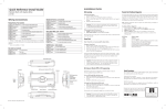
Wiring Diagram
D2D Port (for external
Xpresskit interface module)
Detail
Bitwriter
Port
MINI ATM
RPN: 8540
10A FUSE
Control Center
10A FUSE
MINI ATM
RPN: 8540
+
Control
Center
LED
-
LIGHT FLASH POLARITY
(10A (MAXIMUM) FUSE JUMPER)
+
-
Control
Center
Button
Auxiliary Harness H3
RF Port
Optional Mux Port
(GWA Zone 4)
Door Lock Harness H2
CPU1
Starter Kill Harness
1
4
Main Harness H1
12
1
10
1
8
1
1
Optional Mux Port
(Zone 7)
7
3
© 2009 Directed Electronics. All rights reserved.