1
Not Used
Bitwriter Neutral Safety
Port
Switch
Remote
Start In
Door Lock/
Unlock Output
H2
Port
Relay Out+
Port
Valet
Port
LIGHT FLASH POLARITY
(10A (MAXIMUM) FUSE JUMPER)
Status
+
LED
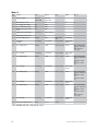
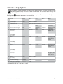
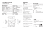
Wiring Connections
RF Port
Main Harness (H1), 12-pin
connector
1
12
10
9
8
7
6
5
4
3
2
1
for IVU
D2D10Port (for external
1
(-) 200mA AUX/TRUNK
OUTPUT
Xpresskit interface module)
H1/1
RED/WHITE
H1/2
RED
H1/3
BROWN
H1/4
WHITE/BROWN
PARKING LIGHT
WIRE - PIN 87a of onboard relay
NotISOLATION
Used
H1/5
BLACK
(-) CHASSIS GROUND
H1/6
VIOLET
(+) DOOR TRIGGER INPUT
H1/7
BLUE
(-) TRUNK PIN/ INSTANT TRIGGER INPUT (N/C OR N/O)
H1/8
GREEN
(-) DOOR TRIGGER INPUT (N/C* OR N/O)
H1/9
BLACK/WHITE
(-) 200mA DOME LIGHT SUPERVISION/FLEX RELAY (Programmable) OUTPUT
H1/10
WHITE/BLUE
200 mA AUX 1 OUTPUT
H1/11
WHITE
H1/12
ORANGE
Bitwriter
10A FUSE
MINI ATM
RPN: 8540
8
Optional Mux Por
(GWA Zone 4)
Detail
MINI ATM
RPN: 8540
Port
(+) SIREN OUTPUT
Optional Mux Por
(Zone 7)
10A FUSE
Control Center
(+)12VDC CONSTANT
INPUT
1
1
CPU1
5
1
ELECTRONICS
+
3
1
12
-
LIGHT FLASH POLARITY
(10A (MAXIMUM) FUSE JUMPER)
+
-
PARKING LIGHT OUTPUT
RF Port
for IVU (-) 500mA GROUND WHEN ARMED OUTPUT
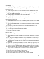
Door Lock Harness (H2), 8-pin connector
MINI ATM
RPN: 8540
10A FUSE
+
-
(10A (MAXIMUM) FUSE JUMPER)
LIGHT FLASH POLARITY
*When using the normally closed setting, this wire only covers one door. Use auxiliary outputs 2, 3 or 4 (as
necessary) programmed as N/C door switch inputs (wired to each individual door of the vehicle) to cover
the other doors. The auxiliary outputs are also programmable as N/O door switchCPU1
inputs so you can connect
multiple doors without the use of diodes.
1
12
When the auxiliaries are programmed for these types of circuits and connected to the vehicle, the alarm
reports a door violation when triggered.
1
10
1
VIOLET*
7
UNLOCK #87 NORMALLY1 OPEN (INPUT)
H2/2
BLUE/BLACK
3
UNLOCK #30 COMMON1 (OUTPUT)
H2/3
BROWN/BLACK
UNLOCK #87a NORMALLY CLOSED
H2/4
VIOLET/BLACK*
LOCK #87 NORMALLY OPEN (INPUT)
H2/5
GREEN/BLACK
LOCK #30 COMMON (OUTPUT)
H2/6
WHITE/BLACK
LOCK #87a NORMALLY CLOSED
H2/7
WHITE/VIOLET
WHITE/BROWN
Optional Mux Port
(Zone 7)
8
H2/1
H2/8
Optional Mux Port
(GWA Zone 4)
CPU1
FLEX RELAY #87 NORMALLY OPEN (INPUT)**
To change
TACH threshold OFF:
jumper
FLEX RELAY #87a
NORMALLY CLOSED**
settings
TACH threshold ON:
1
NOTE: Pin 1 is on the left
12
* Violet and Violet/Black are common at the fuse holder.
1
** These wires work in conjunction withBitwriter
the Black/white
H1/910wire. Door
The Lock/
white/violet
determines
what
the
Neutral Safety Remote
H2
Relay Out
Valet
Status
polarity of the H1/9 wire will be and the white/brown
will
only
be
if Output
a five wire
is required.
1
8
Port
Switch
Start
In used
Unlock
Port circuit
Port
Port
LED
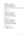
Auxiliary Harness (H3) 7-pin connector
1
7
H3/1
ORANGE/BLACK
1
3
(-) 200mA AUX 4 OUTPUT
H3/2
WHITE/BLACK
(-) 200mA AUX 3 OUTPUT
H3/3
VIOLET/BLACK
(-) 200mA AUX 2 OUTPUT
H3/4
LIGHT GREEN/BLACK
(-) 200mA FACTORY ALARM DISARM OUTPUT
10
H3/5
YELLOW
(+) IGNITION INPUT
1
12
1
5
9
8
7
6
4
3
2
1
10
H3/6
BROWN
(-) 200mA HORN HONK OUTPUT
H3/7
GREY
1
8 N/O)
(-) HOOD PIN INPUT
(N/C OR
R
1
Starter Kill Harness, 3-pin connector
1
GREEN/WHITE
© 2009 Directed Electronics. All rights reserved.
1
5
ELECTRONICS
3
1
12
STARTER - COMMON (KEY SIDE)
5