1
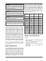
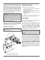
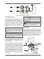
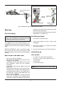
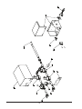
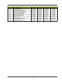
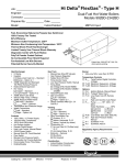
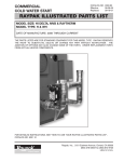
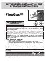
SUPPLEMENTAL INSTALLATION AND
OPERATING INSTRUCTIONS
FlexGas™
For Hi Delta Models
302BD–2342BD
FOR YOUR SAFETY: Do not store or use gasoline or other flammable vapors and liquids
or other combustible materials in the vicinity of this or any other appliance. To do so may
result in an explosion or fire.
NOTE: THIS MANUAL IS SUPPLEMENTAL FOR THE FLEXGAS MODELS OF
THE HI DELTA HEATERS. THIS MANUAL ADDRESSES THE SPECIFIC DIFFERENCES BETWEEN THESE HEATERS AND STANDARD HI DELTA
MODELS. Please refer to the standard Installation and Operating Instruction manuals
(Catalogs 1000.501 and 1000.511 as appropriate) for installation requirements which are not
related to the gas supply.
WHAT TO DO IF YOU SMELL GAS:
• Do not try to light any appliance.
• Do not touch any electrical switch; do not use any phone in your building.
• Immediately call your gas supplier from a neighbor's phone. Follow the gas supplier's
instructions.
• If you cannot reach your gas supplier, call the fire department.
Installation and service must be performed by a qualified installer, service agency or the gas
supplier.
This manual should be maintained in legible condition and kept adjacent to the heater or in another safe place for
future reference.
Catalog No. 1000.58B
Effective: 06-24-08
Patent No. 6,904,873; Other patent pending
Replaces: 02-22-07
P/N 241295 Rev. 3
Rev. 3 reflects the following: Changes to: step 4 of the FlexGas System Start-up section on page 7; the Wiring Diagram
was moved from page 5 to page 9; the addition of: a note to the Attach Manometers to Measure Pressures section on
page 7.
2
2-stage, 8 = 3-stage and 9 = 4-stage). NOTE: Not all
these firing options are available on all heaters.
Refer to the Hi Delta manual for available firing
options. The second group of characters identifies the
size of the heater (four numbers representing the
approximate MBTUH input), and, where applicable, a
letter, indicating the manufacturing series. The final
character is the letter “D” which designates the heater
as a FlexGas equipped heater.
WARNING: Do not use this heater if any part has
been under water. Immediately call a qualified service technician to inspect the heater and to replace
any part of the control system and any gas control
which has been under water.
WARNING: Should overheating occur or the gas
supply valve fail to shut off, do not turn off or disconnect the electrical supply to the heater. Instead, shut
off the gas supply at a location external to the heater.
WARNING: Risk of electrical shock. More than one
disconnect switch may be required to de-energize
the equipment before servicing.
WARNING: This FlexGas heater is intended for
operation on Natural Gas as the primary fuel. DO
NOT use this heater on Propane Gas as the primary
fuel.
Raypak strongly recommends that this manual be
reviewed thoroughly before installing your Hi Delta
heater equipped with FlexGas. Raypak also recommends that the appropriate Hi Delta Installation and
Operating Instruction manual (1000.501 for 302B902B or 1000.511 for 992B – 2342B) be thoroughly
read before attempting to install these heaters. Factory warranty does not apply to heaters that have been
improperly installed or operated. (Refer to the warranty at the back of the standard Hi Delta manuals.)
Installation and service must be performed by a qualified installer, service agency or gas supplier. If, after
reviewing these manuals, you still have questions
which these manuals do not answer, please contact
the manufacturer or your local Raypak representative.
Model
Input
(MBTUH)
Pipe Size
(Nat)
Pipe Size
(LP)
302BD
300
1-1⁄4”
3
402BD
399
1-1⁄4”
3
502BD
500
1
1- ⁄4”
3
652BD
650
1-1⁄4”
3
752BD
750
1-1⁄4”
1-1⁄4”
902BD
900
1-1⁄4”
1-1⁄4”
992BD
990
2”
1-1⁄4”
1262BD
1260
2”
1-1⁄4”
1532BD
1530
2”
1-1⁄4”
1802BD
1800
2”
1-1⁄4”
2072BD
2070
2”
1-1⁄4”
2342BD
2340
2”
1-1⁄4”
⁄4”
⁄4”
⁄4”
⁄4”
Table 1: FlexGas Specifications
Ratings and Certifications
Standards:
•
•
Thank you for purchasing a Raypak product. We hope
you will be satisfied with the high quality and durability
of our equipment.
•
•
Model Identification
The model identification number and heater serial
number are found on the heater rating plate located on
the lower right outside jacket of the heater. The model
number will have the form H9 1262BD or similar
depending on the heater size and configuration. The
letter(s) in the first group of characters identifies the
application (H = Hydronic Heating, WH = Domestic
Hot Water (DHW), P = Pool). The number which follows identifies the firing mode (1 or 4 = on-off, 3 =
3
ANSI Z21.13 · CSA 4.9 - latest edition, Gas-Fired
Hot Water Boilers
CAN 3.1 - latest edition, Industrial and Commercial Gas-Fired Package Boilers
ANSI Z21.56 · CSA 4.7 - latest edition, Gas-Fired
Pool Heaters
ANSI Z21.10.3 · CSA 4.3 - latest edition, Gas
Water Heaters
Installation Codes
All Raypak heaters are National Board Approved, and
design-certified and tested by the Canadian Standards Association (CSA) for the U.S. and Canada.
Each heater is constructed in accordance with Section
IV of the American Society of Mechanical Engineers
(ASME) Pressure Vessel Code, and bears either the
ASME “H” stamp for boilers or “HLW” stamp for water
heaters. The heater also complies with the latest edition of ASHRAE 90.1 Standard.
Installations must follow these codes:
•
•
•
WARNING: Altering any Raypak pressure vessel
by installing replacement heat exchangers, tube
bundle headers, or any ASME parts not manufactured and/or approved by Raypak will instantly void
the ASME and CSA ratings of the vessel and any
Raypak warranty on the vessel. Altering the ASME or
CSA ratings of the vessel also violates national,
state, and local approval codes.
Local, state, provincial, and national codes, laws,
regulations and ordinances
National Fuel Gas Code, ANSI Z223.1/NFPA 54 –
latest edition (NFGC)
National Electrical Code, ANSI/NFPA 70 - latest
edition (NEC)
For Canada only: CAN/CGA B149 Installation Code
(B149.1) and CSA C22.1 C.E.C. Part 1 (C22.1)
Gas Supply
This heater will be connected to 2 different gas supplies (Natural Gas and Propane Gas).
Each gas piping must have a separate sediment trap
ahead of the gas controls. Pounds-to-inches regulators must be installed to reduce the gas supply
pressure to a maximum of 10.5 in. WC for natural gas
and 13.0 in. WC for propane gas. The regulator should
be placed a minimum distance of 10 times the pipe
diameter upstream of the heater gas controls.
Rated inputs are suitable for up to 4,500 ft elevation
without de-rating. Consult the factory for installations
at altitudes over 4,500 ft above sea level.
Component Locations
NOTE: Maintain upright orientation of all components as shown in Fig. 1.
CAUTION: The heater must be disconnected from
the gas supply during any pressure testing of the gas
supply system at test pressures in excess of 1/2 psi
(3.45 kPa).
The heater must be isolated from the gas supply piping system by closing the manual shut-off valves
during any pressure testing of the gas supply piping
system at test pressures equal to or less than 1/2 psi
(3.45 kPa). Relieve test pressure in the gas supply line
prior to reconnecting the heater and its manual shut-off
valves to the gas supply lines. FAILURE TO FOLLOW
THIS PROCEDURE MAY DAMAGE THE GAS
VALVES. Over-pressurized gas valves are not covered by warranty. The heater and its gas connections
shall be leak-tested before placing the appliance in
operation. Use soapy water for leak test. DO NOT use
an open flame.
FlexGas cover not shown for clarity
Fig. 1: Component Locations – Back
4
Low Gas Pressure Switch
(Optional on 302BD-902BD)
Fig. 2: Gas Supply Connection - Top View
Gas Supply Pressure
CAUTION: DO NOT adjust the individual heater
gas valve pressure settings when firing with
propane gas. Propane adjustments (if necessary) should ONLY be made to the FlexGas
propane regulator.
A minimum of 5.0 in. WC and a maximum of 10.5 in.
WC upstream gas pressure is required under load and
no-load conditions for natural gas. A minimum of 8.0
in. WC and a maximum of 13.0 in. WC is required for
propane gas. The gas pressure regulator(s) supplied
on the heater is for low-pressure service. If upstream
gas pressures exceed 14.0 in. WC, intermediate gas
pressure regulators, of the lockup type, must be
installed.
NOTE: DO NOT adjust the FlexGas propane regulator setting without verifying proper operation
including the use of a flue gas analyzer.
Bleeds/Vents
CAUTION: Do not use Teflon tape on gas line pipe
thread. A pipe compound rated for use with natural
and propane gases is recommended. Apply sparingly only on male pipe ends, leaving the two end
threads bare.
This FlexGas gas train is equipped with an propane
gas regulator and low gas pressure switch (optional on
302BD-902BD) which may need to be vented to the
outdoors as required by state and local codes. If these
components are required to be vented, the cover must
be removed and vent lines installed into the components and ran to a suitable location outside the
building in compliance with the NFGC. See Fig.3.
CAUTION: Support gas supply piping with hangers, not by the heater or its accessories. Make sure
the gas piping is protected from physical damage
and freezing, where required.
When connecting additional gas utilization equipment
to the gas piping system, the existing piping must be
checked to determine if it has adequate capacity for
the combined load.
The gas valve pressure regulator(s) on the Hi Delta
heater are nominally preset at 3.5 in. WC. The pressure regulator on the FlexGas propane system is
nominally set at 2.2 ± 0.1 in. WC. This can be verified
by measuring the propane gas pressure at the upper
manifold pressure tap shown in Fig. 5. The pressure at
the gas valve(s) outlet tap, measured with a manometer, while in operation should be 3.5 ± 0.1 in. WC for
natural gas. A nominal pressure of 1.3 in. WC will be
observed at the individual heater gas valve outlet taps
on propane gas. See Fig. 5 for gas pressure measurement locations.
Fig. 3: FlexGas Cover Removal & Vent Locations
5
Propane Supply Pressure
Test Point
Gas Valve
Output Tap
Models: 302BD-902BD
Models: 992BD2342BD
Fig. 4: FlexGas Gas Pressure Measurement Locations
Start-up
•
For Your Safety
Pre Start-up Check
WARNING: If you do not follow these instructions
exactly, a fire or explosion may result causing property damage, personal injury or loss of life.
1. Verify heater is filled with water.
2. Check system piping for leaks. If found, repair
immediately.
This appliance has a hot surface igniter(s). It is
equipped with an ignition device(s) which automatically lights the burners. Do not try to light the burners by
hand.
3. Vent air from system. Air in system can interfere
with water circulation.
BEFORE OPERATING, smell all around the appliance area for gas. Be sure to smell near the floor
because some gas is heavier than air and will settle on
the floor.
4. Purge air from gas lines up to FlexGas gas train.
Initial Start-up
Tools Needed:
WHAT TO DO IF YOU SMELL GAS:
•
•
•
•
•
•
any part of the control system and any gas control
which has been under water.
Check around unit for debris and remove combustible products, i.e. gasoline, etc.
•
•
•
•
•
Do not try to light any appliance.
Do not touch any electrical switch; do not use any
telephone in your building.
Immediately call your gas supplier from a neighbor’s telephone. Follow the gas supplier’s
instructions.
If you cannot reach your gas supplier, call the fire
department.
Use only your hand to push in or turn the gas control knob. Never use tools. If the knob will not turn
by hand, do not try to repair it, call a qualified service technician. Forced or attempted repair may
result in a fire or explosion.
Do not use this appliance if any part has been
under water, immediately call a qualified service
technician to inspect the appliance and to replace
(1)
(4)
(1)
(1)
(1)
12-0-12, 24” scale U-tube manometer
6-0-6, 12” scale U-tube manometers (min.)
Screwdriver
Multi-meter
3/16” Allen wrench
NOTE: Digital manometers are not recommended.
6
Preparation
4. Check if the service regulator is installed and/or
adjust the service regulator.
WARNING: Do not turn on gas at this time.
WARNING: This FlexGas heater is intended for
operation on Natural Gas as the primary fuel. DO
NOT use this heater with Propane Gas as the primary fuel.
Check Power Supply
With multi-meter at incoming power in Hi Delta heater,
check voltage between:
FlexGas System Start-up
Hot - Common (≈120 VAC)
Hot - Ground (≈120 VAC)
Common - Ground (< 1 VAC)
1. Turn off unit. Ensure that the switch on the
FlexGas control is in the position marked “NAT”.
See Fig. 6 for FlexGas control operation. Ensure
the manual valve on the natural gas supply is open
and the manual valve on the propane supply is
closed.
WARNING: If Common - Ground is > 1 VAC,
STOP: Contact electrician to correct ground failure.
Failure to do this may burn out 120V-24V transformer, or may cause other safety control damage or
failure.
2. Turn on the unit, wait 15 seconds, and the igniter
should glow. Look into sight glass located at each
end of the heater to check igniter operation. Gas
valves should open in 45-60 seconds.
Attach Manometers to Measure Pressures
1. Turn off main gas valves.
3. If burner does not light on first trial. It will retry, up
to three times.
2. Attach 24” scale manometer to the first main gas
shut-off valve pressure tapping.
4. Main burner ignition: Check manifold gas pressure at gas valve outlet pressure tap. This should
read 3.5 ± 0.1 in. WC for natural gas. If the natural
gas manifold pressure is not within 3.5 ± 0.1 in.
WC, follow the instructions in the Hi Delta I&O
manual for adjusting manifold pressure. If a flue
gas analyzer is used, the CO2 on natural gas
should be 7.5-8.5% and CO should be less than
150 ppm.
3. Attach (1) 12” scale manometer to the outlet side
of the second main gas shut-off valve pressure
tapping.
4. Attach (1) 12” scale manometer near the fan-proving switch. Pull black cap from air pressure switch
tee and connect the manometer. NOTE: Retain
caps for reinstallation later.
NOTE: Do not adjust Hi Delta valve(s) or manifold
settings when operating on propane. These should
only be adjusted while firing natural gas.
NOTE: The fan(s) pressure is already factory set to
1.4 in. ± .1 in. WC (up to 4500 ft altitude). If adjustment(s) is required, consult the appropriate Hi Delta
manual.
5. When acceptable operation on Natural Gas is confirmed, turn the gas selector key on the FlexGas
control to “OFF”.
Check Gas Supply Pressure
1. Slowly turn on main gas shut-off valve.
6. Close the manual valve on the natural gas supply
then open the manual valve on the propane supply. When the heater shuts off, turn the FlexGas
control key counter-clockwise to the “PRO” position.
2. Read the gas supply pressure from the manometer; minimum supply pressure for natural gas is 5.0
in. WC, recommended supply is 7.0 in. WC, minimum supply pressure for propane gas is 8.0 in.
WC (dynamic readings, all stages firing).
7. Wait 15 seconds, and the igniter should glow. Look
into sight glass located at each end of the heater
to check igniter operation. Gas valves should open
in 45-60 seconds.
3. If the pressure is > 14.0 in. WC, turn off the valve.
7
8. If burner does not light on first trial. It will retry, up
to three times.
NOTE: Reset Low Gas Pressure Switch (when
equipped) if necessary. Refer to Fig. 2 for location.
9. Main burner ignition: Check upper manifold gas
pressure.
From PRO to NAT:
1. Turn the boiler off (power switch on front control
panel).
10. If the pressure readings differ by more than ± 0.1
in. WC, remove screw cover from the gas pressure regulator on the FlexGas fuel train and adjust
until upper manifold pressure is nominally 2.2 ±
0.1 in. WC (manifold pressure 1.3 ± 0.1 in. WC). If
a flue gas analyzer is used, the CO2 on propane
should be 9.0-10.0% and CO should be less than
150 ppm.
2. Turn FlexGas key to “OFF”.
3. Close PRO manual valve.
4. Open NAT manual valve.
5. Turn FlexGas key to “NAT”.
CAUTION: Once the natural gas pressures are
established, DO NOT adjust the Hi Delta gas valves
to attain the required propane pressures.
Adjustments must be made to the FlexGas propane
regulator.
6. Turn the boiler on.
Safety Inspection
1. Check all thermostats and high limit settings.
11. Replace the screw cover.
2. During the following safety checks leave manometers hooked up, check and record.0
CAUTION: Special manifold and air settings may
be required. Verify rating plate and blower housing.
3. If other gas-fired appliances in the room are on the
same gas main, check all pressures on the Hi
Delta with all other equipment running.
12. Turn the gas selector key on the FlexGas control
panel to “OFF”.
4. Check thermostats for ON-OFF operation.
5. Check high limits for ON-OFF operation.
13. Close the manual valve on the propane gas supply
and open the manual valve on the natural gas
supply. Turn the gas selector key on the FlexGas
control clockwise to “NAT”. The heater is now
ready for operation.
6. While in operation, check flow switch operation.
7. Check the low gas pressure switch. (For proper
adjustment, use the attached manometers, if
available, to set pressure. The scales on the
switch are approximate only.) Low gas pressure
switch (if equipped) must be set at 5.0 in. WC for
natural gas.
FlexGas Operation - Changing Fuels
From NAT to PRO:
1. Turn the boiler off (power switch on front control
panel).
Follow-Up
Safety checks must be recorded as performed.
2. Turn FlexGas key to “OFF”.
Turn heater on. After main burner ignition:
3. Close NAT manual valve.
1. Check manometer for proper reading.
4. Open PRO manual valve.
2. Cycle heater several times and re-check readings.
5. Turn FlexGas key to “PRO”.
3. Turn unit off.
6. Turn the boiler on.
8
4. Remove all manometers and replace caps and
screws.
5. Replace all gas pressure caps.
6. Check for gas leaks one more time.
7. Restart unit.
Fig. 5: FlexGas Control Panel
Wiring Diagram
*
*Optional on
302BD–902BD
Fig. 6 Wiring Diagram
9
10
CALL OUT
1-C
2-C
3-C
1-G
2-G
4-G
5-G
6-G
7-G
8-G
1-S
2-S
DESCRIPTION
KEY SWITCH ASSY
RELAY-SPDT 120 VAC
CONNECTOR-WIRE BONDING
GAS SOLENOID VALVE (NAT)
GAS SOLENOID VALVE (PRO)
MANUAL GAS VALVE (NAT)
MANUAL GAS VALVE (PRO)
GAS REGULATOR VALVE
BLEEDLE VALVE
LOW GAS PRESSURE SWITCH
GAS TRAIN COVER
CONTROL BOX w/COVER
302BD-652BD 752BD-902BD 992BD-1262BD 1532BD-2342BD
011943F
011943F
011943F
011943F
012126F
012126F
012126F
012126F
007155F
007155F
007155F
007155F
011910F
011910F
011911F
011911F
012125F
011910F
011910F
011910F
011945F
011945F
007665F
007665F
011944F
011945F
011945F
011945F
011946F
011947F
011947F
011948F
007423F
007423F
007423F
007423F
007187F
007187F
007187F
007187F
011949F
011949F
011950F
011950F
011951F
011951F
011951F
011951F
11
www.raypak.com
Raypak, Inc., 2151 Eastman Avenue, Oxnard, CA 93030 (805) 278-5300 Fax (805) 278-5468
Litho in U.S.A.