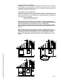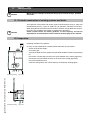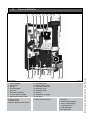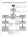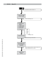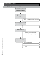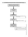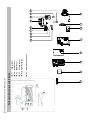
1
Installation & Servicing Instructions High efficiency condensing gas boiler E75CN/E110CN E75CP/E110CP CAUTION! Read this manual thoroughly before installing, servicing, putting into operation or using this boiler and vent system. WARNING! Improper installation, adjustment, alteration, service or maintenance can cause property damage, personal injury or loss of life. Refer to this manual. For assistance or additional information consult a qualified installer or the gas supplier. CAUTION! The user manual is part of the documentation that is delivered to the installation's operator. Go through the information in this manual with the owner/operator and make sure that he or she is familair with all necessary operating instructions. NOTICE! Pictured: E75CN, E110CN E75CP, E110CP Installation and service must be performed by a qualified installer, service technician or the gas supplier. In the Commonwealth of Massachusetts this boiler must be installed by a licensed Plumber or Gas Fitter. - Do not store or use gasoline or other flammable vapors and liquids in the vicinity of this or any other appliance. - WHAT TO DO IF YOU SMELL GAS - Do NOT try to light any appliance. - Do NOT touch any electrical switch. - Do NOT use any phone in your building. - Immediately call your gas supplier from a neighbor’s phone. Follow the gas supplier’s instructions. - If you cannot reach your gas supplier, call the fire department. Address: 103 International Drive, Peachtree City, GA, 30269 Toll-free: 1-800-621-9419 • Fax: 678-829-1666 • www.rinnai.us These instructions to be retained by user. 8U.51.60.01/09.09 Changes reserved. WARNING! If you do not follow these instructions exactly, a fire or explosion may result causing property damage, personal injury or loss of life. Contents of instructions These installation instructions contain important information for the safe installation, start-up and maintanance of boilers with capacities 75,000 through 110,000 BTU/hr. These installation instructions are intended for professional installers, who have the necessary knowledge and are approved for working on heating and gas systems. Subject to technical changes Changes may be made without notice to the illustrations, process steps and technical data as a result of our policy of continuous improvement. Updating of documentation Please contact us if you have any suggestions for improvements or corrections. Find our contact details on the back of this manual. Installation & Servicing Instructions Rinnai E-Series California Proposition 65 lists chemical substances known to the state to cause cancer, birth defects, death, serious illness or other reproductive harm. This product may contain such substances, be their origin from fuel combustion (gas, oil) or components of the product itself. 2 1 2 3 4 5 6 7 8 9 10 11 12 13 14 15 16 17 18 19 Safety and general instructions 1.1 Designated use 1.2 Hazard definitions 1.3 Symbol definitions 1.4 The following instructions must be followed 1.5 Follow these instructions for the space heating water 1.6 Tools, materials and additional equipment 1.7 Relevant Installation, Service and User manuals 1.8 Disposal Regulations and guidelines Description of the boiler Packaging and transportation 4.1 Scope of delivery 4.2 Transportation Installation 5.1 Requirements for the installation room 5.2 Fitting the boiler 5.3 Dimensions 5.3.1 Plumbing kits 5.3.2 Clearances from appliance 5.4 Technical specifications Connecting the boiler 6.1 Central heating system 6.1.1 Plumbing Kit installation 6.1.2 Safety valve 6.1.3 Low water cut off 6.2 Expansion tank 6.3 Underfloor heating system (plastic pipes) 6.4 Gas supply connection 6.4.1. Gas connection with natural gas 6.4.2 Gas connection with propane gas 6.5 Hot water supply 6.6 Condensate drain pipe 6.7 Vent system and air supply system 6.7.1 Intake / Exhaust Guidelines 6.7.2 Examples vent and air supply systems 6.7.3 Installation of the vent system 6.7.4 Recommended vent/air intake terminal position 6.7.5 Dimensioning of the exhaust and air intake duct 6.7.6 Combustion air and vent piping lengths 6.7.7 Calculation of compensation factor 6.7.8 Room Air System (outdoor combustion air) Electrical connections Boiler controls 8.1 Explanation of the function buttons Starting up: Filling and de-aerating the boiler and installation 9.1 Requirements of the water system 9.2 Filling the heating system 9.3 Hot water supply Adjustments 10.1 Altering adjustments 10.2 Activating factory settings (green button function) Isolating the boiler Commissioning 12.1 Testing for gas leaks 12.2 Testing the Ignition Safety shut off device 12.3 Checking for contamination 12.4 Checking of the zero pressure control 12.5 Checking the O2 12.6 Measuring the ionization current 12.7 Installing the casing Maintenance 13.1 Periodic examination of venting and boiler 13.2 Inspection 13.2 Maintenance activities 13.3 Warranty Parts of the boiler Blocks and errors Other errors Spare parts Parts list vent system Common venting guidelines Appendix A Outdoor Reset Sensor Data 4 4 4 4 5 6 6 6 6 7 8 9 9 9 10 10 11 12 14 15 16 17 17 18 19 20 20 21 21 22 23 24 24 25 25 26 28 29 31 32 33 34 37 40 41 42 42 43 44 46 46 49 49 50 51 51 52 53 54 55 55 56 56 56 58 60 61 62 86 92 102 103 104 Installation & Servicing Instructions Rinnai E-Series Content 3 1 Safety and general instructions Please observe these instructions in the interest of your own safety. 1.1 Designated use The boiler is designed for heating water for a central heating system and generating domestic hot water. The boiler is delivered with a burner controller (MCBA) pre-installed. The boiler can be fitted with a modulating outdoor reset sensor ARV12 (included with the boiler) or an On/Off thermostat or relay panel end switch (accessories). 1.2 Hazard definitions The following defined terms are used throughout the documentation to bring attention to the presence of hazards of various risk levels. Notices give important information concerning the operation of the product. ! DANGER DANGER: Indicates the presence of hazards that will cause severe personal injury, death or substantial property damage. ! WARNING WARNING: Indicates the presence of hazards that can cause severe personal injury, death or substantial property damage. ! CAUTION CAUTION: Indicates presence of hazards that will or can cause minor personal injury or property damage. CAUTION CAUTION: Risk of electric shock. Indicates presence of hazards due to electric shock. NOTICE NOTICE: Indicates special instructions on installation, operation or maintenance that are important but not related to personal injury or property damage. Installation & Servicing Instructions Rinnai E-Series i 4 1.3 Symbol definitions The following (safety) symbols may be encountered in these installation instructions and on the unit: This symbol indicates that the unit must be stored away from frost. This symbol indicates that the packaging and/or contents can be damaged as a result of insufficient care taken during transport. This symbol indicates that, whilst still in its packaging, the unit must be protected from weather conditions during transport and storage. 1.4 The following instructions must be followed - - - The boiler must only be used for its designated purpose, as described in the Installation Instructions. Each unit is fitted with a data plate. Consult the details on this plate to verify whether the boiler is compliant with its intended location, e.g.: gas type, power source and venting classification. Only use the boiler with the accessories and spare parts listed. Other combinations, accessories and consumables must only be used if they are specifically designed for the intended application and do not affect the system performance and the safety requirements. Maintenance and repairs must only performed by trained professionals. Installation of a condensing gas boiler must be reported to the relevant gas utility company and have it approved. You are only allowed to operate the condensing gas boiler with the vent system that has been specifically designed and approved for this type of boiler. Please note that local permission for the vent system and the condensate water connection to the public sewer system may be required. ! ! DANGER WARNING DANGER. Gas is flammable and may cause an explosion. Beware if you smell gas: there may be an explosion hazard! If the information in these instructions is not followed exactly, a fire or explosion may result causing property damage, personal injury or death. - Do not store or use gasoline or other flammable vapors and liquids in the vicinity of this or any other appliance. WHAT TO DO IF YOU SMELL GAS - Do NOT try to light any appliance. - Do NOT touch any electrical switch. - Do NOT use any phone in your building. - Immediately call your gas supplier from a neighbor’s phone. Follow the gas supplier’s instructions. - If you cannot reach your gas supllier, call the fire department. Should overheating occur or the gas supply fail to shut off, do not turn off or disconnect the electrical supply to the pump. Instead, shut off the gas supply at a location external to the appliance. Installation & Servicing Instructions Rinnai E-Series You must also respect: - The local building codes stipulating the installation rules. - The local building codes concerning the air intake and outlet systems and the chimney connection. - The regulations for the power supply connection. - The technical rules laid down by the gas utility company concerning the connection of the gas connection to the local gas mains. - The instructions and standards concerning the safety equipment for the water/ space heating system. - The Installation Instructions for building heating systems. - The boiler must be located in an area where leakage of the boiler or connections will not result in damage to the area adjacent to the boiler or to lower floors of the structure. When such locations cannot be avoided, it is recommended that a suitable drain pan be installed under the boiler. - The boiler must be installed in such way that the all components are protected from water (dripping, spraying, rain etc.) during boiler operation and service. - The boiler must not be installed on or against carpeting. - Do not restrict or seal any air intake or outlet openings. - If you find any defects, you must inform the owner of the system of the defect and the associated hazard in writing. 5 1.5 Follow these instructions for the space heating water Unsuitable heating system water can cause the formation of scale or sludge, which affects system efficiency. It can also cause corrosion and reduce life of the heat exchanger. – You must follow Rinnai guidelines for boiler water quality. – Thoroughly flush the system prior to filling. – Follow the Rinnai cleaning instructions. – Never use water that has been treated by salt bedding exchangers, reverse osmosis, D.I., or distilled water to soften the water to fill the heating system. – Do not use inhibitors or other additives unless approved by Rinnai for that purpose! – When frost protection of the heating system is desired, only use Rinnai-approved antifreezes, Noble Noburst Aluminum, or Rhomar RhoGard Aluminum Safe MultiMetal. – When using oxygen-permeable pipes, e. g. for under floor heating systems, you must separate the system from the boiler using plate heat exchangers. – Valve off boiler while flushing system, do not introduce any system cleaner into the boiler loop. Flush system thoroughly to remove all system cleaner before filling boiler. See the Rinnai Boiler Applications Manual and chapter 10 for additional information. 1.6 Tools, materials and additional equipment Installation & Servicing Instructions Rinnai E-Series For the installation and maintenance of the boiler you will need: – Standard tools for space heating, gas and water fitting – Digital manometer, capable of reading both positive and negative pressure (accuracy -0.001” W.C.) – Combustion analyzer (intended for use with condensing boilers) – Digital multimeter – pH digital meter – Metric Allen wrenches – Metric socket wrenches In addition, a handtruck with a fastening belt is useful. 6 For maintenance to the boiler you need, apart from standard tooling for space heating, gas and water fitting the following items: - Rinnai toolkit Q and E-Series 1.7 Relevant Installation, Service and User manuals – Vent system – Rinnai Boiler Applications Manual 1.8 Disposal – Dispose of the boiler packaging in an environmentally sound manner. – Dispose of components of the heating system (e.g. boiler or control device), that must be replaced in an environmentally responsible manner. 2 Regulations and guidelines The installation must comply to the requirements of the authority having jurisdiction or, in the absence of such requirements, to the latest edition of the National Fuel Gas Code, ANSI Z223.1/NFPA 54. In Canada, installation must be in accordance with the requirements of CAN/CSA B149.1, Natural Gas and Propane Installation Code. Where required by the authority having jurisdiction, the installation must comply to the Standard for Controls and Safety Devices for Automatically Fired Boilers, ANSI/ ASME CSD-1. Install CO detectors per local regulations. Boiler requires an inspection every 2 years and maintenance every 4 years or 4000 hours. See maintenance section chapter 14. Operating Limits of the boiler: Max. boiler temperature: 176 °F (80.0 °C) Max. operating pressure: 45 psi (3 bar) Max Allowable Working Temperature ASME: 200 °F (93 °C) Max. Allowable Working Pressure ASME: 45 psi (3 bar) i NOTICE For installations in the Commonwealth of Massachusetts, the following local requirements apply in addition to all other applicable NFPA requirements: For direct- vent boilers, mechanical-vent heating appliances or domestic hot water equipment, where the bottom of the vent terminal and the intake is installed below four feet above grade the following requirements must comply: 1) If not present on each floor level where there are bedrooms, a carbon monoxide detector and alarm must be placed in a living area outside the bedrooms. The carbon monoxide detector and alarm must comply with NFPA 720 (2005 Edition). 2) A carbon Monoxide detector and alarm shall be located in the room that houses the appliance and/or equipment and shall: a) Be powered by the same electrical circuit as the appliance and/or equipment such that only one service switch services both the appliance and the carbon monoxide detector; b) Have battery back-up power; c) Meet ANSI/UL 2034 Standards and comply with NFPA 720 (2005 Edition); and d) Have been approved and listed by a Nationally Recognized Testing Lab as recognized under 527 CMR. 3) A product-approved vent terminal must be used, and if applicable, a product approved air intake must be used. Installation shall be performed in strict compliance with the manufacturer’s instructions. A copy of the installation instructions shall remain with the appliance and/or equipment at the completion of the installation. 4) A metal or plastic identification plate shall be mounted at the exterior of the building, four feet directly above the location of vent terminal. The plate shall be of sufficient size to be easily read from a distance of eight feet away, and read “Gas Vent Directly Below”. Installation & Servicing Instructions Rinnai E-Series The hot water distribution system must comply with all applicable codes and regulations. When replacing an existing boiler, it is important to check the condition of the entire hot water distribution system to ensure safe operation. 7 For direct-vent boilers mechanical-vent heating boilers or domestic hot water equipment where the bottom of the vent terminal and the intake is installed higher than four feet above grade the following requirements must comply: 1)If not present on each floor level where there are bedrooms, a carbon monoxide detector and alarm must be placed in a living area outside the bedrooms. The carbon monoxide detector and alarm must comply with NFPA 720 (2005 Edition). 2) A carbon monoxide detector shall: a) Be located inn the room where the boiler and/or equipment is located; b) Be either hard-wired or battery powered or both; and: c) Shall comply with NFPA 720 (2005 Edition). 3) A product-approved vent terminal must be used, and if applicable, a productapproved air intake must be used. Installation shall be in strict compliance with the manufacturer’s instructions. A copy of the installation instructions shall remain with the appliance and/or equipment at the completion of the installation. 3 Description of the boiler Room sealed boiler The boiler retreives its combustion air from outside then discharges the flue gasses to the outside. Condensing Retrieves heat as much as possible from the flue gasses. Water condensates on the heat exchanger. Modulating Installation & Servicing Instructions Rinnai E-Series Stepless higher or lower burning according to the heat demand. 8 The Rinnai E boiler is a room sealed, condensing and modulating central heating boiler, with an integrated DHW fascility. The boiler is provided with a compact stainless steel heat exchanger with smooth tubes. This design is a well thought out principle using durable materials. The boiler burns gas for supplying heat. The heat is transferred in the heat exchanger to the water in the central heating system. By cooling down the exhaust gases condensate is formed. This results in high efficiency. The condensate, which has no effect on the heat exchanger and the function of the boiler, is drained through condensate collector trap. The boiler is provided with an intelligent control system (CMS Control Management System). The boiler anticipates the heat demand of the central heating system or the domestic hot water facility system. When an outdoor sensor is connected to the boiler it will operate weather dependantly using outdoor reset. This means that the boiler control measures the outside temperature and supply temperature. With this data the boiler calculates the optimal supply temperature for the installation. Explanation of the appliance type: Rinnai E110CN E = Type 110 = Nominal load in (x1000) BTU C = C = Combi N = Natural Gas (P = Propane Gas) Different boilertypes: Combi boiler with integrated DHW fascility E75CN E110CN E75CP E110CP 4 Packaging and transportation 4.1 Scope of delivery The boiler is supplied ready for use. • Please check if the packaging is intact. • Check if all the items listed are included in the delivery. The supply kit is contents: • • • • • • • Boiler with casing; • Template; Automatic air separator (inside the boiler); • Installation instructions; Wall mounting suspension bracket; • User manual; Bronze adapter fittings; • Service manual; 3" PP exhaust adapters (x2); • Outdoor sensor ARV12 Plumbing kit • 3/4" gas shut off valve Fixing material consisting of plugs and screws; 4.2 Transportation CAUTION The boiler may be damaged when not secured properly. • Only transport the boiler using appropriate transportation equipment, such as a handtruck with a fastening belt or special equipment for maneuvering steps. When shipping the boiler must be secured on the transportation equipment to prevent it from falling off. Protect all parts against impacts if they are to be transported. Follow the transportation markings on the packaging. Packaged boilers must always be lifted and carried by two people, or you must use a handtruck or special equipment for transport. Installation & Servicing Instructions Rinnai E-Series ! 9 5 Installation 5.1 Requirements for the installation room ! DANGER - Installation & Servicing Instructions Rinnai E-Series - 10 The room where the boiler will be installed must always be frost free. Do not store or use gasoline or other flammable vapors and liquids in the vicinity of this or any other appliance. Never use or store any chlorinated detergents or halogenated hydrocarbons (e.g. in spraycans, solvents and detergents, paints, adhesives) in proximity of the boiler. The boiler must be installed in such a way that it is protected from water (dripping, spraying, rain, etc.) during boiler operation and service (circulator replacement, condensate trap, control replacement, etc.) This boiler is for intended for indoor installations only. Products to avoid present in boiler room and/or around combustion air intake Spray cans containing chloro-/fluorcarbons Ammonium and/or ammonium solutions Permanent wave solutions Chlorinated waxes and/or cleaners Swimming pool chemicals based on chlorine Calcium chloride used for thawing Sodium chloride used for water softening Refrigerant leaks Paint or varnish removers Hydrochloric acid/muriatic acid Cements and glues Antistatic fabric softeners used in clothes dryers Chlorine-type bleaches, detergents, and cleaning solvents found in household laundry rooms Adhesives used to fasten building products and other similar products Areas likely to have contaminants Dry cleaning/laundry areas and establishments Swimming pools Metal fabrication plants Beauty shops Refrigeration repair shops Photo processing plants Auto body shops Plastic manufacturing plants Furniture refinishing areas and establishments New building construction Remodeling areas Garages with workshops 5.2 Fitting the boiler i NOTICE i NOTICE - Remove the packaging materials. - Lay the boiler on its back during unpacking. Remove the casing from the boiler. This part can be left apart during installation. It must be placed on the boiler and fixed with the screw behind the door and in the 4 quick releases before the boiler is started up. Turn the boiler to its side and remove the wall bracket from the back of the boiler by removing the 2 screws. The boiler can be mounted practically to any wall with the suspension bracket and the enclosed mounting equipment. - The wall must be flat and of sufficient strength in order to be able to securely hold and support the boiler weight with its water content. - Take note of the necessary space around the boiler for installation of venting system, pipework and servicing. See drawing on pages 12 to 15. The location of the boiler can be determined by using the template supplied with the boiler documentation. Remember to account for the spacing of the plumbing kit. Drill the necessary holes using the template Install the mounting bracket to the wall using the supplied mounting materials ! CAUTION Lifting and carrying precautions: To avoid personal injury please follow these recommendations: - Always lift the boiler with 2 people or use special equipment. - When lifting the boiler, bend the knees, and keep the back straight and feet apart. - Do not lift and twist at the same time. - Lift and carry the boiler close to the body. - Wear protective clothing and gloves to protect from any sharp edges. ! WARNING Lift the boiler only by the boiler's rear wall. - Dispose the packaging materials. Installation & Servicing Instructions Rinnai E-Series - 11 5.3 Dimensions ceiling Min. 10" / 250mm D G C F E V 2" 50 0.4" 10 B wall wall A Q S R J P T H N U K L dimensions figure 1 Installation & Servicing Instructions Rinnai E-Series Boiler type 12 A B C D E F G H J K L N P Q R S T U V Height Height with expansion tank Width Depth Left side / vent Center to center / vent and air supply Back / vent Left side / gas pipe Left side / supply pipe Left side / return pipe Left side / condensate pipe Left side / cold water pipe Left side / hot water pipe Pipe length of g* Pipe length of c* Pipe length of f, r, k and w* Back / Center of pipe c, k and w* Back / Center of pipe f, g and r* Pipe length vent co-axial Pipe length vent parallel dimensions Combi E75CN E75CP inches / mm 25.6" / 650 19.7" / 500 15.6" / 395 13.2" / 335 4.7" / 120 10.6" / 270 9.8" / 250 5.9" / 150 13.8" / 350 15.9" / 405 11.2" / 285 8.5" / 215 0.7" / 19 1.6" / 40 2" / 50 1" / 26 2" / 50 3.7" / 95 7" / 177 E110CN E110CP inches / mm 25.6" / 650 34.3" / 870 19.7" / 500 15.6" / 395 13.2" / 335 4.7" / 120 10.6" / 270 9.8" / 250 5.9" / 150 13.8" / 350 15.9" / 405 11.2" / 285 8.5" / 215 8.5" / 215 1.6" / 40 6.3" / 160 1" / 26 2" / 50 3.7" / 95 7" / 177 table 1 Connection for combustion air supply and vent system f wgk r c f wgk r c boiler connections / mounting points figure 2 Combi Vent system / Combustion air supply Gas pipe - g Supply pipe - f Return pipe - r Condensate pipe - c Cold water pipe - k Hot water pipe - w connection diameters E75CN E75CP E110CN E110CP 80/125mm 80/125mm 3/4"M-NPT 0.87" x 3/4"M-NPT / 22mm 0.87" x 3/4"M-NPT / 22mm 0.87" / 22mm 0.59" x 3/4"M-NPT / 15mm 0.59" x 3/4"M-NPT / 15mm 3/4"M-NPT G3/4"x 3/4"M-NPT G3/4"x 3/4"M-NPT 0.87" / 22mm G1/2"x 3/4"M-NPT G1/2"x 3/4"M-NPT table 2 Installation & Servicing Instructions Rinnai E-Series Boiler type 13 5.3.1 Plumbing Kits Rinnai supplies with each type of boiler a Plumbing kit. Find below the dimensions. See chapter 6.1 for additional information. (REF. 16.07) Plumbing Kit 1 (REF. 5.12) 200mm 7.87 (REF. 17.76) Suitable for: E75CN / E75CP E110CN / E110CP 1 1/4” Installation & Servicing Instructions Rinnai E-Series plumbing kit 1 14 1 1/4” 9.00 figure 3 5.3.2 Clearances from boiler ceiling Min. 10" / 250mm 2" 50 24" 600 0.4" 10 wall 15.7" 400 Minimum required clearances to combustibles All types inch / mm Top of boiler 2" / 50 Back of boiler 0" Front of boiler 6" / 150 Left side of boiler 2" / 50 Right side of boiler 2" / 50 Floor / Ground 12" / 300 Vent 0" clearances to the boiler Minimum required clearances to non-combustibles All types inch / mm 2" / 50 0" 6" / 150 2" / 50 2" / 50 12" / 300 0" figure 4 Recommended service clearances All types inch / mm 10" / 250 0 24" / 600 2" / 50 2" / 50 30" / 762 0" For closet installation: clearance is 1” / 25mm from the front. Low Loss Header Clearances to combustible and non-Combustible is 0 inch for sides, top, front and floor/ground table 3 Installation & Servicing Instructions Rinnai E-Series service clearances to the boiler 15 5.4 Technical specifications E-Series Natural gas E75CN E110CN Boiler type Input Hs CH Propane orifice diameter Display indication at start-up Qn Output non-condensing CH Qn Output EN677 efficiency CH Installation & Servicing Instructions Rinnai E-Series Qn Output AFUE CH 16 BTU/hr kW inch / mm BTU/hr kW BTU/hr kW BTU/hr kW Efficiency at 98.6/86°F (36/30°C) part load, % Hs, EN677 CH AFUE according IBR % O2 (at full load) % Electr. power consumption max. W Electr. power consumption stand by W Current V/Hz Fuse rating A Degree of protection acc. EN 60529 Weight (empty) lbs / kg Water content CH gallon / liter Water content DHW gallon / liter After run time pump CH min After run time pump DHW min PMS Water pressure min.-max. PSI / bar PMW Water pressure DHW max. PSI / bar Flow temperature max. °F / °C Pump type Available pump height CH PSI / kPa Approvals gallon/min DHW flow (at 50°F) liter/min DHW flow (at 10°C) DHW flow (at 75°F) gallon/min DHW flow (at 23.9°C) liter/min DHW temperature (T in=50°F (10°C) °F / °C Pressure difference DHW PSI / bar Content expansion vessel gallon / liter Pre-charge pressure expansion vessel PSI / bar CSA number Technical specifications Propane gas E75CP E110CP 75,000 22 n.a. 22.t 67,500 19.8 74,100 21.7 72,400 21.2 110,000 32 n.a. 32.t 98,000 28.8 108,000 31.7 105,700 30.7 75,000 22 0.16" / 4.15 22.tP 67,500 19.8 74,100 21.7 72,400 21.2 110,000 32 0.20" / 5.2 32.tP 98,000 28.8 108,000 31.7 105,700 30.7 98.8 99.0 98.8 99.0 96.1 96.5 96.5 91 / 39 0.9 / 3.5 0.13 / 0.5 UPS20-48 3.8 / 26 2.1 7.9 2.9 / 0.2 2.1 / 8 96.1 4.8 - 5.1 4.4 - 4.7 145 14 120Vac/60Hz 5AF & 4AT IPX4D (IPX0D in case of room air) 101 / 40 91 / 39 1.3 / 5 0.9 / 3.5 0.18 / 0.7 0.13 / 0.5 5 1 14-43 / 1-3 150 / 10 176 / 80 UPS20-58 UPS20-48 0.7 / 5 3.8 / 26 ASME, CSA 4.6 17.4 3.2 2.1 12.1 7.9 176 / 80 4.4 2.9 / 0.2 3.1 / 12 2.1 / 8 14.5 / 1 2183087 Table 4 101 / 40 1.3 / 5 0.18 / 0.7 UPS20-58 0.7 / 5 4.6 17.4 3.2 12.1 4.4 3.1 / 12 6 Connecting the boiler The boiler has the following connection pipes; - The central heating circuit pipes. These must connected to the plumbing kit by means of adapter fittings. See further chapter 6.1; - The gas supply pipe. It is provided with a 3/4" male thread into which the tail piece of the gas valve can be screwed. See further chapter 6.4; - Cold and hot water pipes for domestic hot water (DHW). These consist of 3/4" (15 mm) copper pipe and can be connected to the installation by means of 1/2" M-NPT adapter fittings. See further chapter 6.5; - The condensation drain pipe. It consists of an oval 1" (22 mm) plastic pipe. The drain pipe can be connected to this by means of an open connection. If the open connection is fitted in a different location, then the pipe can be lengthened by means of a 1 1/4" (32 mm) PVC sleeve. See further chapter 6.6; - The vent system and air supply system. It consists of a concentric connection 3"/5" (80/125 mm). The boiler can be converted to a twin pipe connection that will accept 80mm flue and intake air or with the use of the included adapters 3” PVC/CPVC flue and intake. See further chapter 6.7. i NOTICE The pipe to be connected to the boiler must be cleaned before connecting in order to prevent dirt from entering and damaging the boiler. 6.1 Central heating system Connect the central heating system according to its instructions. The boiler pipes can be connected to the installation by means of compression fittings. Reducers should be used for connecting to thick-walled pipe (welded or threaded). i NOTICE i NOTICE i NOTICE When removing the plastic sealing caps from the pipes, dirty testing water may drain from the boiler. A Plumbing Kit must be fitted to the boiler. The boiler, when used in connection with a refrigeration system, must be installed so the chilled medium is piped in parallel with the boiler with appropriate valves to prevent the chilled medium from entering the boiler. The boiler piping system of a hot water boiler connected to heating coils located in air handling units where they may be exposed to refrigerated air circulation must be equipped with flow control valves or other automatic means to prevent gravity circulation of the boiler water during the cooling cycle. Installation & Servicing Instructions Rinnai E-Series i NOTICE 17 6.1.1 i Plumbing Kit installation Rinnai supplies specific Plumbing Kits with each boiler type, which must be fitted directly underneath the boiler on the supply and return pipe. Use of the Rinnai boiler without the plumbing kit will result in the void of warranty. NOTICE To protect the entire heating system we recommend installing a dirt particle trap in the return circuit. When the boiler is installed to an existing heating system this trap is required. Use of a Y strainer is not permitted as substitute for a dirt trap. - i - NOTICE - Install shut-off valves immediately before and after the dirt particle filter to allow the filter to be cleaned. Position 3 (figure 6) is a garden house thread boiler drain, that can be used to drain the boiler or add water tratment additives to the system, such as inhibitors or glycol. Position 4 (figure 6) is the supply connectionfor an idirect tank when used with the optinal 3-way valve kit. For information on locating the expansion tank and system fill, please see the Rinnai Boiler Applications Manual. Thoroughly flush all pipes and radiators. We recommend the use of a Rinnai approved system cleaner. Refer to the Rinnai Boiler Applications Manual for an approved list of Rinnai system cleaners. - Refer to the installation template and chapter 5.3 for the pipe connection dimensions. Fit the bronze adapter fittings, supplied with the boiler (fig. 5, pos. 4) first to the Plumbing Kit and then to the boiler. Connect the expansion tank to the system. See chapter 6.2. Connect the pipes so that they are free from strain. Compression fittings. Parts: 1. Nut 2. Ferrule 3. Fitting 1 Installation & Servicing Instructions Rinnai E-Series Fitting instructions: 18 2 1 4 1. Push the complete fitting over the pipe as far as possible. Ferrule should be over the pipe completely. 2 1. Plumbing kit 2. Safety valve 3. Filling connection 4. Bronze adapter fittings 5. Service valves 6. Flow 1 1/4" 7. Return 1 1/4" 8. External pump 5 3 2. Turn the nut handtight clockwise. 6 7 3 3. Use 2 wrenches, one to hold the fitting on its place, the other for tighten the nut clockwise in 3/4 turn. Plumbing Kit installation 8 fig. 5 The boiler has a self-adjusting and self-protecting control system for the load and the pump capacity. By this means the temperature difference between the supply and return water is checked and controlled. If the installation resistance is over the stated value; the load will be adjusted until an acceptable temperature difference between supply and return water has been obtained. If, after this, the temperature difference is still not acceptable then the boiler will switch off and wait until an acceptable temperature has arisen. If an unacceptable temperature is detected, the control will repeatedly try to achieve water flow over the boiler. If not the boiler will switch off. The electrical side of an external circulation pump (fig. 6, pos. 8) can be connected to the Control Tower. This pump thus switches simultaneously to the boiler pump. The maximum absorbed current consumption of the external circulation pump may not exceed 120V, 2 Amp. If a pump with a larger current draw is required an isolation relay must be used. See the Rinnai Boiler Applications Manual for further information. The extra external pump must be selected according the installation resistance and required flow. As standard the boiler is provided with a water filter in the return pipe of the boiler, so that debris of the central heating water is prevented from affecting the boiler. NOTICE The boiler is designed to be used on pressurized heating systems only. 14 32.3 12 27.7 10 23.0 8 18.5 6 13.8 4 9.2 2 4.6 0 0 0 2 UPS 20-48 UPS 20-48 25% 4 UPS 20-58 UPS 20-58 100% pump index lines 6 8 Q [gallons/min] Resistance E75C Resistance OSS1 10 12 Resistance E110C Resistance OSS2 graph 1 Installation & Servicing Instructions Rinnai E-Series i When using more than one boiler in an installation please refer to the cascade installation instructions. Feet of head NOTICE PSI i 19 6.1.2 i NOTICE 6.1.3 i NOTICE Safety valve An ASME 30 psi pressure relief valve is installed on the plumbing kit included with the boiler. Low water cut off The Rinnai E boiler has a factory installed pressure switch type Low Water Cut Off (LWCO). Check your local codes to see if a Low Water Cut Off is required (LWCO) and if this device conforms to local code. See the Rinnai Boiler Applications Manual for further information. The Low water cut off is not serviceable. 6.2 Expansion tank The E-Series boilers are equiped with an internal expansion tank. The tank of the E75CN and E75CP is positioned inside the boiler casing. This expansion tank has a pre-charge pressure of 14.5 PSI / 1 Bar and a capacity of 2.1 gallon / 8 litres. The tank of the E110CN and E110CP is positioned directly beneath the boiler and together with the casing forms a single entity with the boiler. The casing can be removed by pulling forwards. The expansion tank has a pre-charge pressure of 14.5 PSI / 1 Bar and a capacity of 3.1 gallon / 12 litres. If a larger capacity expansion tank is needed for the installation a standard expansion vessel should be fitted additionally. In that case choose an expansion tank volume, of which the summary is geared to the installation’s water capacity. The pre-charge pressure depends on the installation height above the expansion tank. Fit the expansion tank into the return pipe as close as possible to the boiler. The extra expansion tank should be sourced locally. Please refer to the expansion tank manufacturer for further information. Installation & Servicing Instructions Rinnai E-Series i 20 NOTICE Fill the expansion tank to a minimum of 14.5 psi. 6.3 Underfloor heating system (plastic pipes) When using oxygen-permeable pipes, e. g. for underfloor heating systems, the system must be separated using plate heat exchangers. NOTICE 6.4 ! DANGER ! WARNING ! DANGER No recourse can be made to the terms of the warranty in the event of failure to regard the regulations pertaining to plastic underfloor heating pipes. Gas supply connection Only work on gas lines if you are licensed for such work. If these instructions are not followed exactly, a fire or explosion may result causing property damage, personal injury or death. Rinnai wall mounted boilers are built to run on Natural Gas or Propane Gas. The gas type the boiler is suitable for is indicated on the packaging and on the boiler by a blue label with Natural Gas or a green label with Propane Gas and on the identification plate on the boiler. First check the identification plate on the boiler for the suitable gas type. Do not use the boiler for another type of gas than indicated on the identification plate of the boiler. This will cause improper functioning and can damage the boiler. Natural gas: Propane gas: resume with chapter 6.4.1 resume with chapter 6.4.2 Installation & Servicing Instructions Rinnai E-Series i 21 6.4.1. i Gas connection with natural gas The gas supply connection must comply with local regulations or, if such regulations do not exist, with the National Fuel Gas Code, ANSI Z 223.1. For Canada, the gas connection must comply with local regulations or, if such regulations do not exist, with the CAN/CSA B149.1, Natural Gas and Propane Installation Code. NOTICE Pipe sizing for natural gas Contact gas supplier to size the gas supply line and meter. Gas piping A sediment trap must be installed upstream of the gas controls. The boiler gas pipe is equiped with external 3/4" M-NPT thread, onto which the tail piece of the gas shut off valve can be connected. Use appropiate sealing. The connection to the boiler must include a suitable method of disconnection and a gas control valve must be installed adjacent to the boiler for isolation purposes. The nominal inlet gas pressure measured at the boiler should be 7" W.C. (18 mbar) for Natural gas (Gas A). Maximum pressure with no flow (lockup) or with the boiler running is 10.5 inches W.C. Minimum pressure with the gas flowing (verify during boiler startup) is 5.0 inches W.C. Installation & Servicing Instructions Rinnai E-Series Sediment trap 22 figure 7 The gas pipe must be fitted to the gas valve free from any strain. i NOTICE Make sure that the gas pipe system does not contain dirt, particularly with new pipes. ! DANGER Always check the safety of the gas pipe system by means of a bubble test using leak-search spray. i NOTICE i NOTICE The boiler and its individual shut off valve must be disconnected from the gas supply piping system during any pressure testing of that system at test pressures in excess of 1/2 PSI (3.5kPa). The boiler must be isolated from the gas supply piping system by closing its individual manual shutoff valve during any pressure testing of the gas supply piping system at test pressures equal to or less than 1/2 PSI (3.5 kPa). 6.4.2 i NOTICE Gas connection with propane gas The gas supply connection must comply with local regulations or, if such regulations do not exist, with the National Fuel Gas Code, ANSI Z 223.1. For Canada, the gas connection must comply with local regulations or, if such regulations do not exist, with the CAN/CSA B149.1, Natural Gas and Propane Installation Code. Pipe sizing for propane gas - Contact gas supplier to size pipes, tanks, and 100% lockup gas pressure regulator. Propane Supply Pressure Requirements - Adjust propane supply regulator provided by the gas supplier for 14 inches W.C. maximum pressure. - Pressure required at gas valve inlet pressure port: - Maximum 14 inches W.C. with no flow (lockup) or with boiler running. - Minimum 8 inches W.C. with gas flowing (verify during boiler startup). ! DANGER Ensure that the high gas pressure regulator is installed at least 6 to 10 feet upstream of the boiler. Gas piping - Use a gas shut off valve compatible with propane gases. - A sediment trap must be provide upstream of the gas controls. The boiler pipe is equiped with external 3/4" M-NPT thread, onto which the tail piece of the gas shut off valve can be screwed. Use appropriate sealing. The connection to the boiler must include a suitable method of disconnection. A gas control valve must be installed adjacent to the boiler for isolation purposes. The nominal inlet working gas pressure measured at the boiler should be 12 inch W.C. (30mbar) for Propane gas (Gas E). The gas pipe must be fitted to the gas valve free from any strain. i NOTICE Make sure that the gas pipe system does not contain dirt, particularly with new pipes. ! DANGER Always check the safety of the gas pipe system by means of a bubble test using leak-search spray. i NOTICE The boiler and its individual shut off valve must be disconnected from the gas supply piping system during any pressure testing of that system at test pressures in excess of 1/2 PSI (3.5kPa). i NOTICE The boiler must be isolated from the gas supply piping system by closing its individual manual shutoff valve during any pressure testing of the gas supply piping system at test pressures equal to or less than 1/2 PSI (3.5 kPa). Installation & Servicing Instructions Rinnai E-Series Gas shut off valve onto boiler figure 7 23 6.5 Hot water supply Connection of the drinking water installation should be performed according to the national secondary drinking water regulations. ! DANGER Do NOT use toxic chemicals, such as are used for boiler treatment in potable water heating systems used for space heating. The sanitary water pipes can be connected to the installation by use of adapter fittings. The cold water inlet on the Combi boilers must be equiped with the following components (counted in the water flow direction): Flow regulator valve (supplied), Safety group, Expansion vessel 87 PSI / 6bar (potable water, blue). The 3/4" NPT adapter fitting with flow reducing valve must be fitted in the cold water connection. A flow regulator valve is supplied with the boiler in a 3/4"NPT adapter fitting. The flow regulator valve ensures that a quantity of water is supplied which has a outlet temperature of 120°F (assuming a cold water temperature of 45°F). The quantity of water is virtually unaffected by the water pressure. i NOTICE When there is a water pressure lower than 22PSI / 1.5 bar it is advisable to remove the inside mechanism of the flow reducing valve. 6.6 Condensate drain pipe This boiler produces condensate. Condensate must be drained otherwise the boiler will not function and can cause property damage. The condensation drain pipe should be connected to a drain in the building by means of an open connection. By this means the possibility of drain gases effecting the boiler is prevented. The drain connection should have a minimum diameter of 1.3" / 32mm. Installation & Servicing Instructions Rinnai E-Series Install the condensation drain pipe according to the applicable rules and regulations. 24 If the condensate outlet of the boiler is lower than the public sewage system a condensate pump must be used. The condensate produced by the boiler has a pH value between 3 and 4. Install a neutralization unit if required by the local code. It is recommended, but not required to install a condensate neutralizer. i NOTICE i NOTICE i NOTICE i NOTICE Do not drain the condensation water to the external rain gutter because of the danger of freezing and blockage of the drain. Before putting the boiler into operation fill the condensate trap with 1.27 cups / 300 ml of water. If the boiler will be installed in a high temperature installation such as baseboard, then fill the condensate trap with mineral oil instead of water. Use materials approved by the authority having jurisdiction. In absence of such authority, PVC and CPVC pipe must comply with ASTM D1785, F441 or D2665. Cement and primer must comply with ASTM D2564 or F493. For Canada, use CSA or ULC certified PVC or CPVC pipe, fittings and cement. Periodic cleaning of the condensate disposal system must be carried out. See the Rinnai Boiler Application Manual for further information and for a piping diagram for the condensate. 6.7 Vent system and air supply system Provisions for combustion and ventilation air must be made in accordance with section, Air for Combustion and Ventilation of the National Flue Gas Code, ANSI Z223.1, or Sections 7.2, 7.3 of 7.4 of CAN/CGA B149.1, Installation Codes, or applicable provisions of the local building codes. - i NOTICE 6.7.1 Do not store chemicals near the boiler or in rooms where the air is being supplied to the boiler. See the list on page 10. Do not allow the flue gases of other appliances to enter the boiler. Keep cabinet free of moisture In the event that the system has actuated to shut off the main burner gas, do not attempt to place the boiler in operation. Contact a qualified service agency. Intake / Exhaust Guidelines • • • • • • • • • • • • i NOTICE You must use vent components that are certified and listed with this model. Do not combine vent components from different manufacturers. Venting should be as direct as possible with a minimum number of pipe fittings. Avoid dips or sags in horizontal vent runs by installing supports per the vent manufacturer’s instructions. Support horizontal vent runs every four feet and all vertical vent runs every six feet or in accordance with local codes. Vent diameter must not be reduced. The boiler is unsuitable to install on a common vent installation, see also chapter 19. Do not connect the venting system with an existing vent or chimney. Do not common vent with the vent pipe of any other water heater or appliance. Vent connections must be firmly pressed together so that the gaskets form an air tight seal. Refer to the instructions of the vent system manufacturer for component assembly instructions. If the vent system is to be enclosed, it is suggested that the design of the enclosure shall permit inspection of the vent system. The design of such enclosure shall be deemed acceptable by the installer or the local inspector. If it becomes necessary to access an enclosed vent system for service or repairs, Rinnai is not responsible for any costs or difficulties in accessing the vent system. Warranty does not cover obtaining access to an enclosed vent system. Installation & Servicing Instructions Rinnai E-Series Refer to the specific instructions on your vent product for additional installation requirements. 25 6.7.2a Examples vent and air supply systems (concentric) Wall thickness for vent termination installation: Examples wall terminals Minimum: 100mm / 4” Maximum: 508mm / 20” Short termination with wall terminal figure 9A Termination with wall terminal on higher level figure 9B Installation & Servicing Instructions Rinnai E-Series Examples roof terminals 26 Short termination with roof terminal figure 10A Termination with roof terminal and bends figure 10B 6.7.2 b Examples vent and air supply systems (parallel) Wall thickness for vent termination installation: Examples sealed combustions Minimum: 100mm / 4” Maximum: 508mm / 20” Horizontal with concentric termination figure 11A Horizontal with parallel termination figure 11B 10" MINIMUM INSIDE EDGE T`O INSIDE EDGE Vertical vent and horizontal air intake figure 11C Vertical with concentric termination figure 11D Vertical with parallel termination figure 11E Installation & Servicing Instructions Rinnai E-Series 12" OVER MAXIMUM SNOW LEVEL OR 24" WHICHEVER IS GREATER 27 6.7.3 Installation of the vent system i NOTICE Consult local and state codes pertaining to special building code and fire department requirements. Adhere to national code requirements. i NOTICE Follow the listed maximum length of vent systems, which are boiler output dependent. The maximum permissible lengths are listed in table 9, chapter 6.7.6. Decide how to install the exhaust and air intake system. You can choose between: Concentric system (see page 26) The concentric connection is provided standard initially. The boiler concentric connection diameter is 3"/5" (80/125 mm), to which the venting and air supply system can be fitted, with or without elbow pieces. The maximum permissible pipe length is displayed in table 9, chapter 6.7.6. Parallel system (see page 27) The boiler can be converted to a parallel system with supplied adapters. It is possible to use a parallel pipe connection of 2x 3". In this case a seperate supplied kit, with 2 vent adapters 3" (ø80mm), cover 5" (ø125mm), vent exhaust pipe and gaskets should be fitted instead of the concentric vent adapter on top of the boiler. See figure 12 for installation. The maximum permissible pipe length is set out in table 9, chapter 6.7.6. Room Air System (outdoor combustion air) The boiler can use room air for combustion. If this option is selected the boiler must first be converted to the Parallel system. A single exhaust pipe can then be fitted. It is required to use a room air filter when using indoor air for combustion. The maximum permissible pipe length is set out in table 9, chapter 6.7.6. i NOTICE We advise to install a vent system out of the venting system program supplied by Rinnai (See chapter 19 Parts list Vent system). For further information about the available components of the venting and air supply system we recommend you consult Rinnai and the Installation instructions and parts list documentation. A B C 10 D 9 7 2 4 6 Installation & Servicing Instructions Rinnai E-Series 8 28 3 5 1 boiler conversion from concentric to parallel A. 1. Push the 2 clips slightly outwards B. 2. Pull the concentric adaptor out of the boiler 3. Press the cover in the connection at the back from inside out C. 4. Push the 3" adapter into the connection at the back of the boiler (= air intake) 5. Pull the rubber seal around the bottom of the exhaust connector 6. Push the exhaust connector in the boiler, in the boiler exhaust pipe until 'CLICK' 7. Push the 5" cover over the exhaust connector in the 5" opening until 'CLICK' 8. Push the rubber plug in open position in the O2 measuring opening and close the stop. 9. Push the gasket around the top of the exhaust connector 10. Push the 3" exhaust adaptor in the exhaust connector. D. Connect the parallel vent system. figure 12 6.7.4 Recommended vent/air intake terminal position Terminals should be positioned as to avoid products of combustion entering openings into buildings or other vents. Maintain 12” of clearance above the highest anticipated snow level or grade or, whichever is greater. Please refer to your local codes for the snow level in your area. Terminal positions Description A Clearance above grade, veranda, porch, deck, or balcony B Clearance to window or door that may be opened Canadian Installations - Direct Vent and non Direct Vent US Installations Direct Vent US Installations non Direct Vent 12 inches (30 cm) 12 inches (30 cm) 12 inches (30 cm) 6 inches (15 cm) for appliances < 10,000 6 inches (15 cm) for appliances < 10,000 4 feet (1.2 m) below or to Btuh (3 kW), 12 inches (30 cm) for apBtuh (3 kW), 9 inches (30 cm) for ap- side of opening; 1 foot (300 pliances > 10,000 Btuh (3 kW) and < pliances > 10,000 Btuh (3 kW) and < mm) above opening 100,000 Btuh (30 kW), 36 inches (91 cm) 50,000 Btuh (30 kW), 12 inches (91 cm) for appliances > 100,000 Btuh (30 kW) for appliances > 50,000 Btuh (30 kW) C Clearance to permanently closed window * * * D Vertical clearance to ventilated soffit, located above the terminal within a horizontal distance of 2 feet (61 cm) from the center line of the terminal * * * E Clearance to unventilated soffit * * * F Clearance to outside corner * * * G Clearance to inside corner * * * H Clearance to each side of center line ex- 3 feet (91 cm) within a height 15 feet (4.5 tended above meter/regulator assembly m) above the meter/regulator assembly * * I Clearance to service regulator vent outlet * * J Clearance to nonmechanical air supply 6 inches (15 cm) for appliances < 10,000 6 inches (15 cm) for appliances < 10,000 4 feet (1.2 m) below or to inlet to building or the combustion air inlet Btuh (3 kW), 12 inches (30 cm) for apBtuh (3 kW), 9 inches (30 cm) for ap- side of opening; 1 foot (300 to any other appliance pliances > 10,000 Btuh (3 kW) and < pliances > 10,000 Btuh (3 kW) and < mm) above opening 100,000 Btuh (30 kW), 36 inches (91 cm) 50,000 Btuh (30 kW), 12 inches (91 cm) for appliances > 100,000 Btuh (30 kW) for appliances > 50,000 Btuh (30 kW) K Clearance to a mechanical air supply inlet L 36 inches (91 cm) 6 feet (1.83 m) 3 feet (91 cm) above if within 10 feet (3 3 feet (91 cm) above if witm) horizontally hin 10 feet (3 m) horizontally Clearance above paved sidewalk or paved driveway located on public property 7 feet (2.13 m) [1] * 7 feet (2.13 m) M Clearance under veranda, porch, deck, or balcony 12 inches (30 cm) [2] * * [1] A vent shall not terminate directly above a sidewalk or paved driveway that is located between two single family dwellings and serves both dwellings. [2] Permitted only if veranda, porch, deck, or balcony is fully open on a minimum of two sides beneath the floor. * For clearances not specified in ANSI Z223.1/NFPA 54 or CSA B149.1, clearances are in accordance with local installation codes and the requirements of the gas supplier. clearances of venting system terminals table 6 Installation & Servicing Instructions Rinnai E-Series Ref figure 14 29 6.7.4 i NOTICE ! CAUTION ! CAUTION i NOTICE i NOTICE i NOTICE i NOTICE Recommended vent/air intake terminal position Terminals should be positioned as to avoid products of combustion entering openings into buildings or other vents. Maintain 12” of clearance above the highest anticipated snow level or grade or, whichever is greater. Please refer to your local codes for the snow level in your area. The termination shall be at least 4 feet (1,220 mm) for the US and 6 feet (1,830 mm) for Canada distance from electric meters, gas meters, regulators and relief equipment. (for room air application only) Horizontal vent systems should always be installed sloping towards the boiler (min. 21 mm/m, 1/4 “/ feet), in order to avoid condensate retaining in the vent system. With the condensate running back to the boiler the risk of ice forming at the terminal is reduced. The whole route of the vent system must be installed upwards, never downwards, completely nor partly. Place pipe supports every 4 feet (1219 mm) of horizontal run, beginning with the support near the boiler to prevent movement in fittings and allow boiler to be free from any strain or weight on boiler or fittings. The terminal should be located where dispersal of combustion products is not impeded and with due regard for the damage or discolouration that might occur to building products in the vicinity (see fig 14 and 15). Item Description Plastic Vent and/or air pipes and fittings Installation & Servicing Instructions Rinnai E-Series Plastic Pipe cement and primer 30 Item Description Stainless steel vent systems Plastic Vent and/or air pipes and fittings Flue Material PVC Schedule 40 PVC - DWV CPVC Schedule 40 PVC CPVC Approval Codes for Installation United States ANSI/ASTM D1785 ANSI/ASTM D2665 ANSI/ASTM F441 ANSI/ASTM D2564 ANSI/ASTM F493 Flue Material Manufacturer AL29-4C Heat Fab PPS Ubbink US/CAN UL1738 Approval codes for installation of venting system Equivalent friction loss of PVC/CPVC EXHAUST 12" (300 mm) minimum Terminal positions PVC Fittings or Piping Equivalent feet 45 degree elbow 3 90 degree elbow 6 plastic pipe per foot 1 concentric vent kit 3 12" (300 mm) minimum 12" (300 mm) minimum INTAKE Flue system concentric Saf-T Vent SC twin pipe Saf-T Vent EZ Seal Rolux Condensing Vent System 12" (300 mm) minimum 12" (300 mm) minimum figure 15 table 7 m 0.91 1.83 0.30 0.91 table 8 i NOTICE In certain weather conditions condensation may also accumulate on the outside of the air inlet pipe. Such conditions must be considered and where necessary insulation of the inlet pipe may be required. In cold and/or humid weather water vapor may condense on leaving the vent terminal. The effect of such ‘water condensation’ must be considered. The terminal must be located in a place not likely to cause a nuisance. Use the Instructions of the Rinnai venting system for installation and service. Cellular or Foam core PVC is not permitted for use with the boiler. ! DANGER ! WARNING i ! NOTICE WARNING Dimensioning of the exhaust and air intake duct The wall mounted boiler must be vented and supplied with combustion and ventilation air as described in this section. Ensure the vent and air piping and the combustion air supply comply with these instructions regarding vent system, air system, and combustion air quality. Inspect finished vent and air piping thoroughly to ensure all are airtight and comply with the instructions provided and with all requirements of applicable codes. Failure to provide a properly installed vent and air system may cause severe personal injury or death. Use only the material listed in Rinnai's vent documentation for vent pipe, and fittings. Failure to comply could result in severe personal injury, death or substantial property damage. i NOTICE Installation must comply with local requirements and with the National Fuel Gas Code, ANSI Z223.1 for U.S installations or CSA B 149.1 for Canadian installations. i NOTICE For closet and alcove installation, CPVC material (instead of PVC) must be used in a closet/alcove structure. Failure to follow this warning could result in fire, personal injury, or death. All vent pipes must be connected and properly supported, and the exhaust must be pitched a minimum of a 1/4” inch per foot back to the boiler (to allow drainage of condensate). Please refer to the venting manufacturer's manual to see if a larger pitch is required for specific venting sytems. For the Room Air System, combustion air piping from the outside MUST BE used. Use of combustion air from indoor rooms using louvers, plenums, or any other devices is not authorized. See the Rinnai Boiler Applications Manual for further information on venting. Installation & Servicing Instructions Rinnai E-Series 6.7.5 31 6.7.6 Combustion air and vent piping lengths. In the table below you find the maximum equivalent pipe length of the vent/air system based on 3" diameter. These lengths are for single pipe (room air), twin pipe, and concentric venting systems. Boiler type E75 E110 3” Max Vent equivalent length 100 feet 100 feet Equivalent vent length 3” Max Air equivalent length 100 feet 100 feet table 9 Calculation of equivalent length vent system Choose the vent type and fill out the corresponding table. * When determining equivalent combustion air and vent length, add 6 feet for each 90° elbow, 3 feet for each 45° elbow, 5 feet for the concentric terminal in the Parallel System, and 2 feet for the concentric terminal in the Concentric System . Parallel system Length tube Number of elbows 90° x 6* Combustion air Vent Number of elbows 45° x 3* Concentric terminal Add 5 ft.* ft ft ft ft ft ft ft ft Concentric system Length concentric tube, boiler to roof horizontal Number of elbows 90° x 6* ft Number of elbows 45° x 3* ft Concentric terminal Add 2 ft.* ft ft Installation & Servicing Instructions Rinnai E-Series Example of calculation: Twin tube (parallel) with terminal Combustion air length Vent length 32 Calculation: Equivalent Air Length Equivalent Vent Length : 24 ft : 24 ft Total Multiply with factor ft Equivalent length 0.5 ft ft 0.5 Total equivalent length Total ft ft Multiply with Total equivalent factor length ft 1.0 ft with elbow 3 x 90° with elbow 2 x 90°, elbow 2 x 45° : (24+3x6+2) x 0.5 : (24+2x6+2x3+2) x 0.5 = = 23 ft 23 ft +Total = 46 ft. 6.7.7 Calculation of compensation factor The compensation factor eliminates or reduces the natural effect of derate of maximum input caused by the resistance of the vent system and/or the impact of the altitude. 1. Determine the Compensation Factor Vent System CF(V) in the table below. Eq. length (ft) min 0 11 21 31 41 61 81 max 10 20 30 40 60 80 100 Boiler type E75 E110 CF (V) 0 0 0 0 0 2 1 4 2 6 3 8 4 10 Compensation factor vent system CP(V) table 10 2. Determine the Compensation Factor Altitude CF(A) in the table below. Altitude (ft) min 0 1,000 2,000 3,000 4,000 5,000 6,000 7,000 8,000 9,000 max 1 2,000 3,000 4,000 5,000 6,000 7,000 8,000 9,000 10,000 Boiler type E75, E110 CF (A) 0 6 12 18 24 30 36 42 48 54 Compensation factor altitude CP(A) NOTICE Any application or installation above 10,000 must be reviewed by Rinnai's Engineering group. This is to ensure the product is installed and the overall system is designed properly and that the units are commisioned properly. Not involving of Rinnai's Engineering group would result in no support of the product and no warranty. 3. Calculate the Compensation Factor Total CF(T): CF(T) = CF(V) + CF(A) The result is the setting for Parameter 73. Change parameter 73 according to this result. See Chapter 10.1 how to change parameters. ! WARNING Example of calculation: E110 Eq. lenth vent system (taken from previous example) 46 ft Altitude 7,200ft Parameter setting (Par. 73) = 48 CF(V) = 6 CF(A) = 42 + CF(T) = 48 Do not overcompensate the boiler by setting a higher value than calculated, otherwise the boiler could be seriously damaged. Installation & Servicing Instructions Rinnai E-Series i table 11 33 6.7.8 Room Air System (indoor combustion air) When using indoor air, Rinnai strongly recommends the use of an indoor air filter, P/N 808000025. This boiler requires adequate combustion air for ventilation and dilution of flue gases. Failure to provide adequate combustion air can result in unit failure, fire, explosion, serious bodily injury or death. Use the following methods to ensure adequate combustion air is available for correct and safe operation of this water heater. Important: Combustion air must be free of corrosive chemicals. Do not provide combustion air from corrosive environments. Appliance failure due to corrosive air is not covered by warranty. Combustion air must be free of acid forming chemical such as sulfur, fluorine and chlorine. These chemicals have been found to cause rapid damage and decay and can become toxic when used as combustion air in gas appliances. Such chemicals can be found in, but not limited to bleach, ammonia, cat litter, aerosol sprays, cleaning solvents, varnish, paint and air fresheners. Do not store these products or similar products in the vicinity of this water heater. Unconfined Space: An unconfined space is defined in NFPA #54 "as a space whose volume is not less than 50 cubic feet per 1000 Btu/hr (4.8 m3 per kW per hour) of the aggregate input rating of all appliances installed in that space. Rooms communicating directly with the space in which the appliances are installed, through openings not furnished with doors, are considered a part of the unconfined space." If the “unconfined space” containing the appliance(s) is in a building with tight construction, outside air may still be required for proper operation. Outside air openings should be sized the same as for a confined space. 25FT 36FT Installation & Servicing Instructions Rinnai E-Series 25FT 34 NOTE: 8FT CEILING Unconfined space 36FT NOTE: 8FT CEILING Unconfined Space Unconfined Space 91,300 BTU Boiler 200,000 BTU Boiler figure 16 Confined Space: (Small Room, Closet, Alcove, Utility Room, Etc.) A confined space is defined in the NFPA #54 as "a space whose volume is less than 50 cubic feet per 1000 Btu/hr (4.8 m3 per kW per hour) of the aggregate input rating of all appliances installed in that space." A confined space must have two combustion air openings. Size the combustion air openings based on the BTU input for all gas utilization equipment in the space and the method by which combustion air is supplied: Using indoor air for combustion Using outdoor air for combustion Louvers and Grills When sizing the permanent opening as illustrated in figure 17, consideration must be taken for the design of the louvers or grills to maintain the required free area required for all gas utilizing equipment in the space. If the free area of the louver or grill design is not available, assume wood louvers will have 25% free area and metal louvers or grills will have 75% free area. Under no circumstance should the louver, grill or screen have openings smaller than ¼”. Example: Wood: 10 in x 12 in x 0.25 = 30 in2 Metal: 10 in x 12 in x 0.75 = 90 in2 Location To maintain proper circulation of combustion air two permanent openings (one upper, one lower) must be positioned in confined spaces. The upper shall be within 12 inches of the confined space and the lower opening shall be within 12 inches of the bottom of the confined space. Openings must be positioned as to never be obstructed. Combustion air provided to the appliance should not be taken from any area of the structure that may produce a negative pressure (i.e. exhaust fans, powered ventilation fans). Gas Vent / Boiler Exhaust BOILER PERMANENT OPENINGS 12in. MAX OUTLET AIR DUCT BOILER 12" (300mm) INLET AIR DUCT Louvers and grills 10" (250mm) figure 17 Installation & Servicing Instructions Rinnai E-Series 12in. MAX 35 Using Indoor Air For Combustion When using air from other room(s) in the building, the total volume of the room(s) must be of adequate volume (Greater than 50 cubic feet per 1000 Btu/hr). Each Combustion air opening must have at least one square inch of free area for each 1000 Btuh, but not less than 100 square inches each. Using Outdoor Air For Combustion Outdoor air can be provided to a confined space through two permanent openings, one commencing within 12 in. (300mm) of the top and one commencing within 12” (300mm) of the bottom, of the confined space. The openings shall communicate to the outside by one of two ways: directly through horizontal ducts indirectly through vertical ducts When communicating directly with the outdoors through horizontal ducts, each opening shall have a minimum free area of 1 in2/2000 Btu/hr (1100 mm2/ kW) of total input rating of all appliances in the confined space. Note: If ducts are used, the cross sectional area of the duct must be greater than or equal to the required free area of the openings to which they are connected. When communicating indirectly with the outdoors through vertical ducts, each opening shall have a minimum free area of 1 in2/4000 Btu/hr (550 mm2/ kW) of total input rating of all appliances in the confined space. Combustion air to the appliance can be provided from a well ventilated attic or crawl space. Gas Vent / Boiler Exhaust Gas Vent / Boiler Exhaust OUTLET AIR OUTLET AIR DUCT Installation & Servicing Instructions Rinnai E-Series BOILER 36 BOILER INLET AIR INLET AIR DUCT Ventilation Louvers for unheated crawl space Gas Vent / Boiler Exhaust BOILER OUTLET AIR INLET AIR DUCT [Ends 1Ft (300mm) above floor] Louvers and grills figure 18 7 Electrical connections The electrical connections to the boiler must be made in accordance with all applicable local codes and the latest revision of the National Electrical Code, ANSI/NFPA-70. Installations should also conform with CSA C22.1 Canadian Electrical Code Part 1 if installed in Canada. Devices such as, outdoor sensor, room thermostat or temperature control, temperature sensor or thermostat and an external pump are all connected to the internal connection terminal. The connection terminal is situated behind the Control Tower. Connecting incoming power Install a 120V main switch next to the boiler as service main switch of the boiler. Lead the cable through the back part of the boiler using a strain relief and lead the cable through the cable supports to the Control Tower. Connect a power supply cable to the cable harness terminal strip that connects to both the power switch on the front of the Control Tower and the terminal strip with positions 1, 2, and 3 on the inside of the Control Tower. The boiler must be electrically grounded in accordance with local codes, or in absence of local codes, with the National Electrical Code, ANSI/INFPA 70 and/or the CSA C22.1, Electrical Code. RISK OF ELECTRIC SHOCK. Once the main power supply is on then there is 120V on terminals 1 to 12 if the main switch next to the boiler is switched on. CAUTION - NOTICE The Rinnai room thermostat and controls must be connected to their allocated connections. All other types or makes of room thermostats or controls which are used must have a Volt free contact. No changes may be made to the wiring of the boiler; All connections should be designed in accordance with the applicable regulations; ! CAUTION External safety contact 24 V~ 100 mA 24 Volts maximum 100 mA Room therm. On / Off External safety contact Bus Outside Controller sensor On/off thermostat or control (Volt free) Cylinder connection three-way valve DHW sensor CH DHW N Bus room thermostat L 11 ARV12 outdoor sensor 7 N 10 internal three-way valve motor and DHW sensor 120 V~ 120 Volts 120 V~ Ext.controller 120 Volts for external control 120 Volts for external pump 120 V~ External pump N L 4 5 6 main power supply 120 V~ Power supply 8U352200 When using an on/off thermostat or control, it is possible that an anticipating resistance must be calibrated in order to prevent too high temperature fluctuations. As a standard rule this means mercury thermostats. This resistance wire is present in the Control Tower and must be connected to clamps 23 and 27. The anticipating resistance in the room thermostat has to be set at 0.11 A. For more detailed questions regarding the components which are not supplied, the distributor should be contacted. Connection terminal E-Series CAUTION Make sure that the power consumption of each of the terminals 4-5-6, 7-8-9 and10-11 does not exceed 230W or 2 Amp. Connection terminal figure 19 Installation & Servicing Instructions Rinnai E-Series i CAUTION 37 2 Amp. max. Installation & Servicing Instructions Rinnai E-Series X7 ! E-Prom 120V Flowswitch T 220°F 120V 120V figure 15 CAUTION Label all wires prior to diconnection when servicing or replacing controls. Wiring errors can cause improper and dangerous operation electrical diagram 38 5 Installation & Servicing Instructions Rinnai E-Series electrical ladder diagram 39 figure 15a 8 Boiler controls The boiler is provided with a fully automatic microprocessor control, called CMS Control Management System. This control simplifies operation by undertaking all major control functions. Initially when power to the unit is switched on it will remain on standby. There is no indication LED on, until one of the program buttons is pressed. The control panel display will show the relevant state. When the installation is empty the display will show FILL. The various parameters can be called up in two ways: The Good-state or standard read out The first way shows a simple display read out. The boiler in operation will always show 'Good'. When a message is necessary this will be shown instead of Good. Example Example i NOTICE Technical read out The second way is a technical read out. In normal situations the following will be shown: • on the left the status in which the boiler is active; • on the right the supply temperature in °F; Alternately indicated by: • the water pressure in the installation in PSI. When a message (error or blocking code) is necessary this will be shown instead of the technical read out. To switch over from the Good-state to the Technical read out (and vice versa): - Press the STEP-button for 5 seconds. When the system has been filled the automatic de-aeration program starts, when a program has been selected, by pressing the button for Central Heating, DHW or pump Installation & Servicing Instructions Rinnai E-Series program ( , of ). The program takes 17 minutes and stops automatically. After this the unit will function normally. (See also 'Filling and de-aerate the boiler and installation, chapter 9). 40 On a call for heating or hot water the control system will select the required water control temperature. This water temperature is called the T-set value. On a call for central heating the boiler ignites first at low input. The input is then changed slowly to match the load required. The boiler operates in this way to avoid excessive water noises and temperature overshoot. On a call for domestic hot water supply the T-set value of central heating return water temperature is monitored. Depending on the amount of domestic water which is withdrawn from the DHW fascility, the central heating return water temperature, from which the input is adjusted, will vary. Operation indication (in the first display position by technical read out) 0 1 2 3 4 5 6 7 8 9 A No heat demand Fan pre/post purge Ignition phase Burner active on central heating Burner active on DHW Fan check Burner off when room thermostat is demanding Pump overrun phase for central heating Pump overrun phase for hot water Burner off because of to high flow temperature Automatic de-aeration program 8.1 Explanation of the function buttons 2 1 3 7 4 6 5 8 Boiler control panel i NOTICE figure 16 Only qualified personel who are trained for servicing these boilers are permitted to make alterations in the controller to calibrate the boiler to the installation. 1. Display. See previous page for further information. 2. ON-OFF Switch (Placed separately next to the boiler) This switch turns the power supply to the boiler on or off. ! CAUTION Only turn the boiler off using this switch, when the burner is off.. 3. Central Heating program button. Switching the Central Heating on or off (LED on/off); 4. Hot Water program button. Switching the Domestig Hot Water (DHW) facility on or off (LED on/off); 5. Pump program button. adjusts the pump to continuous water circulation in the central heating system (LED on), or according to the pump overrun times on the relevant programs (LED off); NOTICE When the pump is switched on continuously it can lead to undesired heating up of the central heating system during the summer. 6 Mode-button. After briefly pressing, a selection of the data chapters can be retrieved. After pressing for 5 seconds it is possible to enter the code as described in chapter 11.3; 7 Step-button. After briefly pressing, the water pressure can be retrieved and pages per chapter can be retrieved. After pressing for 5 seconds it switches from the Good-state to technical read out and vice versa; 8 Reset-button. After briefly pressing, for: - unlocking errors; - ending the access code; After pressing for 5 seconds an operating stop is made, for example, for activating the automatic venting program. Some buttons have other functions.These functions are only active when according to the procedure described in chapter 10, adjustment has to be changed or data must be retreived from the CMS. The other functions are: 3. Central Heating program button : 4. Hot Water program button: 5. Pump program button : 7. Step-button: + function; - function; store-function, which means that by means of this button a modified setting is confirmed; scrolling in a data chapter. Installation & Servicing Instructions Rinnai E-Series i 41 9 Starting up: Filling and de-aerating the boiler and installation ! CAUTION i NOTICE i NOTICE ! WARNING CAUTION Observe the following rules of safety: - All work on the unit must take place in a dry environment. - Rinnai units may never be in operation without their housing, except in connection with maintenance or adjustments (see Chapter 12 and 13). - Never allow electrical or electronic components to come into contact with water. NOTICE Carry out the following tasks in connection with maintenance, etc. to an alreadyinstalled unit: - Shut down all programs - Close the gas shut off valve - Shut off the power at the main power switch - Close the service valves (system supply and return) NOTICE Take note of the following when maintenance or adjustments are needed: - The unit must be able to function during these activities; for this reason, the unit’s supply voltage, gas pressure and water pressure must be maintained. Ensure that this is not a source of potential danger during these activities. Following maintenance or other activities; always check the installation of all parts through which gas flows (with bubble test using leak-search spray). 9.1 Requirements of the water system Before filling the heating system, the complete system, including all zones, must be thoroughly cleaned and flushed to remove sediment. Flush until clean water runs free of sediment. Rinnai suggests using an approved system cleaner to flush the system, but not the boiler. See the Rinnai Boiler Applications Manual for furtherinformation and for a list of approved cleaners. Approved antifreezes are Noble Noburst Aluminum, Rhomar RhoGard Aluminum Safe Multi-Metal. Never use salt bedding exchangers, reverse osmosis, D.I., or distilled water for filling the heating system. Installation & Servicing Instructions Rinnai E-Series ! 42 WARNING Do not use petroleum-based cleaning or sealing compounds in the boiler system. Damage of seals and gaskets in boiler and system could occur, resulting in substantial property damage. The central heating installation needs to be filled with potable water. ! WARNING Use only potable water or approved glycol for filling the heating system. When the water hardness of the filling water exceeds > 10.5 gpg (200 mg/L) and the volume of the installation > 20L/kW (5.2 gallons/3,412 BTU) the water has to be treated until below the maximum value of 10.5 gpg (200 mg/L). The pH value of the installation water must be between 6.5 and 8.5. Check the The pH value using a digital pH meter that has been properly calibrated or by having the water analyzed by a water treatment company. If pH differs from above, contact Rinnai engineering for further assistance. i NOTICE Failure to adhere to the water quality requirements will result in a void of warranty. Freeze protection Freeze protection for new or existing systems must use glycol that is specially formulated for this purpose. This includes inhibitors, which prevent the glycol from attack the metallic components. This should be for multi-metallic components. Make certain to check that the system fluid is correct for the glycol concentration and inhibitor level. The system should be tested at least once a year and as recommended by the producer of the glycol solution. i NOTICE ! WARNING i NOTICE Use only Rinnai approved inhibitors. See the Rinnai Boiler Applications Manual for an approved list of inhibitors. Use only inhibited propylene glycol solutions, which are specially formulated for central heating systems. Ethylene glycol is toxic and can attack gaskets and seals used in the boiler and system. Approved glycols ae listed in the Rinnai Boiler Applications Manual. Additives in the installation water are not permitted. 9.2 Filling the heating system For filling or topping up the installation you use the filling loop according to the following procedure: 1 Switch on the power supply; 2 The display will show FILL; 3 All functions off (heating , DHW and pump ); 4 Push briefly the 'STEP'-button: P XX (XX = water pressure in PSI); 5 Open the filling loop (Indication on display increases); 6 Fill up slowly to 22 to 25 PSI; 7 STOP appears on the display; 8 Close the filling loop; 9 De-aerate the complete installation, start at the lowest point; 11 Close the filling loop; 12 Activate the functions in use (heating , DHW and/or pump ); 13 If A XX appears on the display, wait for 17 minutes; 14 Check the water pressure and if necessary top it up to 22 to 25 PSI 15 Close the filling loop; 16 Press the ‘STEP’-button; 17 Be sure that the filling loop is closed. 18 After the automatic de-aeration program (A XX) is finished the boiler will return to the Good state or Technical read out. Check the water pressure regularly and top off the installation when necessary. The working pressure of the installation should be between 22 and 25 PSI when the system is cold. Installation & Servicing Instructions Rinnai E-Series 10 Check the water pressure and if necessary top it up; 43 i NOTICE It can take a while before all air has disappeared from a filled installation. Especially in the first week noises may be heard which indicate the presence of air. The automatic air vent in the boiler will remove this air, which means the water pressure can reduce during this period and therefore topping off with water will have to be done. During normal use the following messages can occur with the necessary follow up: Water pressure is too low (<10 PSI), FILL indication remains continuously visible, the boiler is taken out of operation. The installation needs to be topped off. Water pressure is too low (<14,5 PSI), flashing FILL will alternate with indication of water pressure, boiler power of 50% is possible. The installation needs to be topped off. Water pressure is too high (>52,2 PSI), if HIGH indication remains continuously visible, the boiler is taken out of operation. The installation pressure needs to be decreased by draining water. 9.3 Hot water supply Apply the water pipe pressure to the DHW fascility (open main valve and/or stop valve of the safety group). Installation & Servicing Instructions Rinnai E-Series Vent the DHW fascility and the hot water installation by opening a hot water shut off valve. Leave the shut off valve open for as long as required until all air has disappeared from the DHW fascility and the pipes and only water is flowing from the shut off valve. 44 FOR YOUR SAFETY READ BEFORE OPERATING WARNING: If you do not follow these instructions exactly, a fire or explosion may result causing property damage, personal injury or loss of life. A. This appliance does not have a pilot. It is equipped with an ignition device which automatically lights the burner. Do NOT try to light the burner by hand. B. BEFORE OPERATING smell all around the appliance area for gas. Be sure to smell next to the floor because some gas is heavier than air and will settle on the floor. WHAT TO DO IF YOU SMELL GAS - Do NOT try to light any appliance. - Do NOT touch any electrical switch. - Do NOT use any phone in your building. - Immediately call your gas supplier from a neighbor’s phone. Follow the gas supplier’s instructions. - If you cannot reach your gas supplier, call the fire department. C. Use only your hand to push in or turn the gas control knob. Never use tools. If the knob will not push in or turn by hand, don’t try to repair it, call a qualified service technician. Force or attempted repair may result in a fire or explosion. D. Do not use this appliance if any parts have been under water. Immediately call a qualified service technician to inspect the appliance and to replace any part of the control system and any gas control which has been under water. OPERATING INSTRUCTIONS STOP! Read the safety information above this label. Turn off al electrical power of the appliance. Set the thermostat or other operating control to the lowest setting. This appliance is equipped with an ignition device which automatically lights the burner. Manual Gas Valve (Main valve) Do NOT try to light the burner by hand. CLOSE OPEN 5. Close main gas shut off valve. 6. Wait (5) minutes to clear out any gas. Then smell for gas. Including near the floor. If you smell gas, STOP! Follow “B” in the safety information above on this label. If you don’t smell gas, go to the next step. 7. Open main shut off valve. 8. Set the thermostat or other operation control to desired setting. 9. Turn on all electric power to the appliance. 10. If the appliance will not operate, follow the instructions “To Turn Off Gas To Appliance” and call your service technician or gas supplier. TO TURN OFF GAS TO APPLIANCE 1. Turn off all electric power to the appliance if service is to be performed. 2. Set the thermostat or other operating control to the lowest setting. 3. Close main gas shut off valve. 8U.34.01.00 / 05.09 Installation & Servicing Instructions Rinnai E-Series 1. 2. 3. 4. 45 10 Adjustments When the boiler is installed it is ready for use. All adjustments of the boiler control are already pre-programmed for a heating system with radiators/convectors with a supply temperature of 185°F. The adjustments are described in the Parameter chapter on page 44. In certain cases parameters have to be altered in case of : - Lower supply temperature - High altitude/long vent length Read through the Parameter chapter to adjust the boiler to its installation. Contact Rinnai in case of doubt. i NOTICE Only qualified personel who are trained for servicing these boilers are permitted to make alterations in the controller to calibrate the boiler to the installation. 11.1 Altering adjustments STEP 1 Press the Mode-button for 5 seconds. The display shows COdE followed by an arbitrary number; STEP 2 Press by means of the + or the - button until the code C123 is shown; STEP 3 Press the STORE-button to confirm the code (code blinks1 x). Now you have acces to the installer level. There are 4 chapters: • • • • Parameters Information chapter (no adjustments possible) Service chapter Error-chapter (no adjustments possible) Installation & Servicing Instructions Rinnai E-Series The content of the chapters is described on the following pages. 46 STEP 4 Press briefly the MODE-button to select one of the 4 chapters, i.e. PARA; STEP 5 Press once or more briefly on the STEP-button to select a Parameter (parameter visible on the left, value on the right) ; STEP 6 Alter the value, if necessary/possible, by means of the + or the - button STEP 7 Press briefly on the STORE-button to confirm the alteration. When you have to change more values, repeat from step 5. STEP 8 Press once or more on the MODE-button until StBY or Good is shown: After a few seconds the text StBY will be replaced by the technical read-out or Good-state (Depending from the position the acces code is entered) When you want to return from an arbitrary position to the original read out press once or more on the MODE-button until StBY is shown. i NOTICE If no single button is used within 20 minutes the display will return automatically to its original read-out (Good state or technical read out) PARA . 1 2* FACTORY . 186°F 00 DESCRIPTION maximum supply temperature CH type of CH installation: . radiators with large surface areas or underfloor heating as additional heating: T max. supply 158°F K factor heating curve 1.8; gradient 10°F/min; gear differential 10°F 3 4* max. 00 5* 6* 7* 10* 11* 14 15* 2.3 1.4 14°F 0°F 0°F 10°F/min. 00 23 27 31 36 26°F 32°F 132°F 20 43 49 73 max. 100% 0 89 00 90 . . INFO . FACTORY . Info Mode 1 4 5 7 8 16 17 18 20 21 22 23 24 25 26 32 37 46 . °F °F °F °F °F % kW kW GJ GJ GJ h h h h h h . 01 DO NOT USE 02 under floor heating with radiators as additional heating: T max. supply 140°F; K factor heating curve 1.5; gradient 8°F/min; gear differential 8°F 03 full under floor heating: T max. supply 122°F; K factor heating curve 1.0; gradient 6°F/min; gear differential 6°F 04 maximum power CH in kW (.. x3415 = .. BTU/hr) control principal with on / off thermostat: 100 % on / off thermostat 100 % on / off weather dependant heating curve K-factor (see also heating curve graph) heating curve exponent (see also heating curve graph) heating curve climate zone (see also heating curve graph) fine adjustment heating curve day temperature fine adjustment heating curve night temperature gradient speed °F/min. Booster after night decrease*: no yes Frost Temperature Minimum T-set CH DHW temperature Type of three way valve DHW fascility VC 2010 / VC 8010 Flowswitch Maximum power DHW in kW (.. x3415 = .. BTU/hr) Maximum pump capacity heating Altitude and venting CFT. See chapter 6.7.7 min-max Address No function Bus thermostat Display reading °C and Bar °F and PSI 01 RANGE . 68 - 186°F 00 01 0.2 - 3.5 1.1 - 1.4 -4 - 32°F -8 to 10°F -8 to 10°F 0 - 28°F/min. 00 01 -4 to 50°F 0 - 158°F 68 - 176°F x0 2x min-max 100 % 0 - 100 -01 00 00 01 . . . RANGE . DESCRIPTION supply water temperature T1 return water temperature T2 DHW temperature T3 outdoor temperature T4 flue gas temperature T5 (optional sensor) actual power in % actual power in kW (.. x3415 = .. BTU/hr) actual load in kW (.. x3415 = .. BTU/hr) indication bus communication consumption total in GJ (.. x 33 = .. m3) consumption CH in GJ (.. x 33 = .. m3) consumption DHW in GJ (.. x 33 = .. m3) total number of burner run hours number of burner run hours CH number of burner run hours DHW total number of hours counter total number of run hours pump CH and DHW within how many hours is service required . Installation & Servicing Instructions Rinnai E-Series Parameter Mode 47 Service Mode 1 2 3 4 SERV . OFF OFF OFF OFF VALUE . Error Mode ERRO VALUE Err.L - Err.5 1 2 3 °F 4 °F 5 kW 6 % DESCRIPTION boiler in operation with burner function on fan adjustable and burner off pump adjustable with burner on showroom position ON = active and OFF = non active RANGE OFF - max. OFF - max. OFF - max. ON - OFF . . DESCRIPTION Last saved error until 5 last previous errors error code operation status boiler supply water temperature T1 return water temperature T2 load (.. x3415 = .. BTU/hr) pump capacity Parameter-, Info-, Service- and Error-chapters i NOTICE Table 12 * Most of the data in this table can be requested by the RS100. Most of the adjustments which are stated in this table are unnecessary when in combination with the Rinnai RS100 thermostat and will be taken care of by the RS100 itself and do not have to be adjusted. For further information regarding to the RS100 thermostat refer to the Rinnai RS100 installation manual. Outdoor reset 230 Heat curve day Heat curve night 212 2.30 194 1.80 48 flow water temperature in °F 2.00 1.75 158 140 1.50 122 1.00 104 1.00 0.50 86 68 68.0 64.4 60.8 57.2 53.6 50.0 46.4 42.8 39.2 35.6 32.0 28.4 24.8 21.2 17.6 14.0 10.4 6.8 3.2 -0.4 50 -4.0 Installation & Servicing Instructions Rinnai E-Series 176 outside temperature in °F heating line adjustments Parameter Step 6 and 7 graph 2 10.2 Activating factory settings (green button function) To activate the factory settings again please follow the next procedure (Note: all altered adjustments will be set back to their orignial factory settings): - Select, when necessary, the technical read out; - Select with the MODE-button chapter PARA; - Press the STORE-button. The word "Copy" will appear and the factory settings are active again. 11 Isolating the boiler Some situations require turning the entire boiler off. By switching off the three buttons with the LED's for central heating, hot water and , or ), the boiler is switched off. Do not shut off the power pump program ( of the boiler, which means the circulation pump and the three-way valve are activated once every 24 hours in order to prevent these parts from seizing up. CAUTION In the event of frost danger during an isolated boiler it is advisable to drain the boiler and/or the installation. Installation & Servicing Instructions Rinnai E-Series ! 49 12 i Commissioning NOTICE Work on the boiler must be carried out by a competent person, using correctly calibrated instruments with current test certification. These installation instructions are intended for professional installers, who have the necessary knowledge and are approved for working on heating and gas systems. Before the boiler is fired, ensure that the boiler and the system are well de-aerated and free of air. Purge the gas line between the gas meter and the boiler. i NOTICE The boiler and its individual shut off valve must be disconnected from the gas supply piping system during any pressure testing of that system at test pressures in excess of 1/2 PSI (3.5kPa). To commission the boiler the casing has to be removed. - remove the 4 screws A,B,C and D in the quick releases of the casing (figure 17); - remove the screw E behind the door on the front of the casing (figure 17); - remove it towards the front. The boiler settings, such as burner pressure and adjustment of the air quantity are unnecessary, due to the fact that the boiler operates with a zero pressure control. This means the correct gas quantity is controlled by the suction operation of the fan. The fine adjustment which is carried out at the factory is once-only, which means that adjusting of these values is unnecessary. Only in case of replacing of the gas valve, venturi and/or fan, the zero pressure and the incorrect O2 adjustment has to be checked and, if necessary, adjusted at the right value. ! DANGER Always check the installation of all parts through which gas flows (by bubble test using leak-search spray) Installation & Servicing Instructions Rinnai E-Series During the commissioning of the boiler the Rinnai Installation, Commissioning, and Service card must be filled out. 50 Removing casing figure 17 12.1 Testing for gas leaks Prior to start-up of the boiler you must check the external tightness of the gas supply valve and confirm this in the start-up report. ! WARNING ! DANGER - Cover endangered positions before leak testing. Do not spray the leak testing agent onto cables, plugs, electrical connection lines or electronic circuit boards. Do not allow it to drip onto them either. Leaks may be caused to pipes and screw connections during commissioning and maintenance activities. - Carry out a proper leak test. - Only use approved leak detection agents for leak detection. - Disconnect the heating system from the power supply. - Check the exterior tightness of new conduit sections up to and including the direct sealing point on the gas burner fitting. The maximum test pressure allowed on the input of the gas burner fitting is 14 inch W.C. (35mbar). 12.2 Testing the Ignition Safety shut off device WARNING Switch off system using the Central Heating button and the DHW button - Disconnect the plug and socket connection of the ionization cable. - Switch on the sytem using the Central Heating button and the DHW button. - Press the MODE-button for 5 seconds. - The display will show COdE followed by an arbitrary number; - Select by means of the - Press the Store-button to confirm the code (code blinks 1 x); - Press the MODE-button until SERV is shown; - Press the STEP-button once until 1 is shown; alternately 1 and OFF will be shown. - Press the button once; Check if the boiler does one start-up attempt and four restart attampts. After the last start-up attempt, the boiler will lock out. The gas valve is shut off. The E02 code is blinking in the display. - Connect the plug and socket connection of the ionisation cable. - Press the reset button. or the button the code C123; - Check if the boiler starts-up. Do not touch the inside of the igntion cable while it is disconnected during start up of the boiler. Installation & Servicing Instructions Rinnai E-Series ! - 51 12.3 Checking for contamination i NOTICE In order to be able to check the boiler for contamination in the following running years it is advisable to measure the maximum air displacement in the boiler when putting the boiler into operation. This value can be different with each type of boiler. In order to be able to measure this value follow the next procedure: - Press the MODE-button for 5 seconds. - The display will show COdE followed by an arbitrary number; - Select by means of the - Press the Store-button to confirm the code (code blinks 1 x); - Press the MODE-button until SERV is shown; - Press the STEP-button until 2 is shown; alternately 2 and OFF will be shown. - Turn open the upper measuring nipple on the gas valve (fig. 18); - Connect the hose of the digital pressure gauge to the upper measuring nipple of the gas valve - Press the button until the maximum value is achieved; The fan will function to its maximum revolutions (burner stays off) - Measure the under pressure and write down this value. At the next servicing visit this value may drop 20% of its original value on the moment of installation. When this value is dropped more than 20% the boiler needs maintanance. or the button the code C123; Check point contamination figure 18 Installation & Servicing Instructions Rinnai E-Series i 52 NOTICE - Press the button until OFF is shown (keep button pressed) With this the procedure is finished. 12.4 Checking of the zero pressure control i NOTICE The zero pressure control is set at the factory. To measure this value you need a difference pressure gauge with a range of +0,2 to -0,8 mbar (+0.08 to -0.001” W.C.). Follow the next procedure: - Press the MODE-button for 5 seconds. - The display will show COdE followed by an arbitrary number; - Select by means of the - Press the Store-button to confirm the code (code blinks 1 x); - Press the MODE-button until SERV is shown; - Press the STEP-button once until 1 is shown; alternately 1 and OFF will be shown. - Turn the upper measuring nipple on the gas valve open (fig. 19); - Connect the hose of the digital pressure gauge to the upper measuring nipple of the gas valve - Press the button until the minimum value is achieved; The fan will function to its minimum revolutions (burner is active) - Measure the negative pressure. Value should be 0 to -4Pa (0 to -0.04 mbar or 0 to -0.016" W.C.). Check point contamination figure 19 or the button the code C123; If the zero pressure deviates too much: Remove black cover of the gas valve Remove cap with Torx screwdriver (fig. 20) Turn slightly the Torx screw behind the cap: Turn left is positive pressure deviation Turn right is negative pressure deviation Adjustment zero pressure figure 20 - Ending this procedure is done by pressing the Reset button. - Proceed by checking the O2 value and correct it if necessary. Installation & Servicing Instructions Rinnai E-Series - 53 12.5 Checking the O2 i The O2 percentage is factory-set. This has to be checked at commissioning, maintance and faults. NOTICE This can be checked by means of the following procedure: - Remove the black cover of the gas valve by unscrewing the sealed screw. - i Installation & Servicing Instructions Rinnai E-Series checkpoint CO2 54 i figure 21 Put the boiler into operation and take care that it can deliver its heat; Tip: If there is no demand for heat on CH, turn the hot water tap completely open and measure the O2. - Press the MODE-button for 5 seconds. - The display will show COdE followed by an arbitrary number; - Select by means of the - Press the Store-button to confirm the code (code blinks 1 x); - Press the MODE-button until SERV is shown; - Press the STEP-button once until 1 is shown; alternately 1 and OFF will be shown. - Calibrate the O2 meter ; - Place the probe of the O2 meter into the check point (see fig. 21); or the button the code C123; button until the maximum value (in kW) is achieved; - Press the The boiler will burn on full load (value on display in kW) value in BTU/hr = x3415 - Check the O2 percentage: Natural gas: full load: between 4.4% and 4.7% min. load: between (setting of full load +0.2%) and 6.0% Propane: full load: between 4.8% and 5.1% min. load: between (setting of full load +0.2%) and 6.0% Example:Full load set on 4.6% O2 (natural gas) then the minimum load setting should be between 4.8% and 6% O2 NOTICE adjustment screw CO2 figure 22 Choose the right O2 value according the kind of gas (Natural Gas or Propane Gas). Wrong adjustment may result causing property damage, personal injury or death. - Let the O2 meter do its measuring procedure. - Adjust, if necessary, the adjustment screw to correct the O2 value (see fig. 22). Ending the O2 measuring procedure: - Press the - button until OFF is shown (keep button pressed). With this the procedure has ended.. - Replace the black cover on the gas valve and fix it with the screw. 12.6 Measuring the ionization current - Switch off the system using the Central Heating button and the DHW button - Disconnect the plug and the socket connection on the probe and connect the measuring device in series. See figure 23. Select the µA direct current range on the measuring device. The measuring device must have a resolution of at least 1 µA. - Switch on the sytem using the Central Heating button and the DHW button. - Press the MODE-button for 5 seconds. - The display will show COdE followed by an arbitrary number; - Select by means of the - Press the Store-button to confirm the code (code blinks 1 x); - Press the MODE-button until SERV is shown; - Press the STEP-button once until 1 is shown; alternately 1 and OFF will be shown. or the Ionization test figure 23 button the code C123; button until the maximum value (in kW) is achieved; - Press the The boiler will burn on full load (value on display in kW) value in BTU/hr = x3415 - Measure the ionization. When the boiler is in full load the ionization current must be > 4 µA and write down this value in the log book. - Press the - Switch off the system using the Central Heating button and the DHW button - Disconnect the measuring device and restore the plug and the socket connection on the probe. - Switch on the sytem using the Central Heating button and the DHW button. 12.7 Installing the casing Installing casing figure 24 - Install the cover on the boiler and clos all 4 quick releases of the casing - Tighten the 4 screws A,B,C and D in the quick releases (figure 24); - Tighten the screw E behind the door on the front of the casing (figure 24); Installation & Servicing Instructions Rinnai E-Series button until OFF is shown (keep button pressed). 55 13 i Maintenance Maintenance or changes to the boiler may only be carried out by a qualified technician. NOTICE 13.1 Periodic examination of venting systems and boiler i The inspection of the boiler and venting system should be done every 2 years and full maintenance every 4 years or 4000 hours of operation, whichever occurs first.. When doing this the circumstances of the boiler’s location must be taken into account. From this one can determine whether to deviate from this advice. Please contact Rinnai for further guidance on the frequency and service requirements. Contact details can be found on the back page of this manual. NOTICE 13.2 Inspection Preparing the boiler for inspection Installation & Servicing Instructions Rinnai E-Series To carry out the maintenance activities please follow the next procedure: - switch off the power supply; - shut off the gas; - valve off the boiler from the system using the boiler isolation valves in the plumbing kit. - remove the 4 screws A,B,C and D in the quick releases of the casing (figure 25); - remove the screw E behind the door on the front of the casing (figure 26); - remove it towards the front. - clean the casing with a cloth with a simple (non-abrasive) cleaning agent; 56 Removing casing figure 25 Removing casing figure 26 14.2.1 Visual inspection for general signs of corrosion - 14.2.2 Check all gas and water pipes for signs of corrosion. Replace any pipes that are corroded. Measuring the ionization current See subsection 12.6 “Measuring the ionization current". 14.2.3 Measuring the inlet gas pressure See subsection 6.4.1 and .2 “Gas connection with natural gas" and "Gas connection with propane”. 14.2.4 Checking and adjusting the gas/air ratio See subsection 12.4 “Checking of the zero pressure control”. 14.2.5 Testing for gas leaks See subsection 12.1 “Testing for gas leaks”. 14.2.6 Carrying out a pressure test of the heating system See chapter 9.2 “Filling the heating system”. Checking venting systems Check the following points: - Is the prescribed combustion air/flue system used? - Have the instructions for configuring the flue system as specified in the relevant Installation instruction for the flue gas system been observed? - Check air intake and flue gas for obstruction or damage. Installation & Servicing Instructions Rinnai E-Series 14.2.7 57 13.2 Maintenance activities i NOTICE 2 9 1 4 The fan unit and burner cassette (figure 27 to 29) (2 and 4 year maintenace) - remove the electrical connection plug from the gas valve (1) and fan motor (2); - loosen the nut (3) of the gas pipe under the gas valve; - replace the gasket with a new one; - loosen the front cross head screw (4) of the black plastic silencer; - after this turn the two clamping rods (9 and 10) ¼ turn and remove them by pulling them forward. Note the correct turning direction (red indicator. fig. 29); - slightly lift the fan unit and remove it towards the front of the heat exchanger; - remove the burner cassette out of the fan unit; - check the burner cassette for wear, pollution and possible cracks. Clean the burner cassette with a soft brush and vacuum cleaner. 3 fan unit and gas valve figure 27 i If burners are cracked replace the complete burner cassette; - replace the gaskets between burner and fan unit and the gasket between fan unit and heat exchanger; - check the venturi and the gas-air distribution plate for pollution and clean this part, if necessary with a soft brush and vacuum cleaner. If the air box contains a lot of dirt it is plausible that the fan itself is dirty as well. To clean this, the fan has to be removed from the hood and the venturi. Clean the fan with a soft brush and a vacuum cleaner. Replace the gasket and ensure that all gaskets of the fan parts are mounted correctly. NOTICE 10 figure 28 i Heat exchanger (2 and 4 year maintenance) - check the heat exchanger for contamination. Clean this if necessary with a soft brush and a vacuum cleaner. Prevent dirt falling down into the heat exchanger. Flushing the heat exchanger from the top down is not permitted NOTICE Installation & Servicing Instructions Rinnai E-Series Refitting of the components is done in reverse order. 58 ! Make sure that during refitting the clamping rods they are put in the right position. They should be turned vertical. If the boiler should activated with clamping rods in the wrong position it will cause serious property damage, personal injury or loss of life. DANGER Clamping rods figure 29 Ignition electrode (4 year or 4000 hour maintenance) The replacement of the electrode is only necessary when the electrode is worn off. This can be checked by measuring the ionisation current. The minimum ionisation current has to be higher than 4µA on full load. If the inspection glass is damaged the complete electrode must be replaced. Replace the ignition assembly after 4 years or 4000 hours, whichever occurs first. Replacement goes as follows: - remove the electrical connections of the electrode; - press the clips on both sides of the electrode to both sides and remove the complete electrode; - remove and replace the gasket; Refitting of the components is done in reverse order. 9 7 8 Siphon figure 30 13 14 12 11 Condensate tray ! figure 31 Condensate trap and condensate tray (figure 30-32) (2 and 4 year maintenance) Step 1: Condensate trap - first remove the screw (7); - pull the condensation cup (8) downwards, out of the condensate tray (14) Check this for impurities. If there is not a lot of impurities it is not necessary to clean the condensate tray (Go to Step 3). If there is a lot of impurities in the cup it is necessary to remove and clean the condensate tray according Step 2; - check the O-ring (9) of the cup and replace if necessary; - clean the parts by flushing it with clean water; - grease the O-ring again with acid free O-ring grease to make fitting easier; - if there is a leak at the condensate trap (8) replace complete condensate trap by S4421200; Step 2: Condensate tray - remove the plug from the flue gas sensor if present; - turn the two short clamping rods (11 and 12) ¼ turn and remove them by pulling them forward; Note the right turning direction (red indicator); - lift the exhaust pipe (13) out of the condensate tray (14); - press the condensate tray (14) carefully downwards and remove it by pulling it forward; - replace the gasket between condensate tray and heat exchanger by a new one; - clean the condensate tray with water and a hard brush; - check the condensate tray on leaks. Step 3: Refitting is done in reverse order. Note that all gaskets seals completely. Make sure that during refitting the clamping rods they are put in the right position. They should be turned vertical. If the boiler should activated with clamping rods in the wrong position it will cause serious property damage, personal injury or loss of life. DANGER ! figure 32 DANGER ! WARNING If replacement by new gaskets and burner mentioned in this chapter is not done within the service interval subscribed by Rinnai the boiler can be damaged and will cause serious property damage, personal injury or loss of life. Use only original spare parts supplied by Rinnai. If other parts will be used the boiler can be damaged and will cause serious property damage, personal injury or loss of life. Use of non-Rinnai parts will result in the void of warranty. Installation & Servicing Instructions Rinnai E-Series Put the boiler into operation and check the O2 (see page 50). Clamping rods 59 Visual inspection of the flame The burner must flame evenly over the entire surface when operating correctly. The flame must burn with a clear, blue, stable flame. Check the flame through the inspection glass in the ignition probe (fig. 33). The flame pattern should be as shown in the figures below. SATISFACTORY Ignition probe Inspection glass blue flame figure 33 UNSATISFACTORY Ignition probe yellow flame Further checks: - Inspect the pressure relief valve - Clean the water filter in the return pipe - Check the pH of the water or glycol/water mixture. Verify proper operation after servicing. Installation & Servicing Instructions Rinnai E-Series 13.4 Warranty 60 For warranty conditions refer to the warranty card supplied with the boiler. 14 Parts of the boiler 4 2 1 3 5 7 15 14 6 T1 P1 T5 T2 T3 8 16 heat exchanger ignition unit fan unit air inlet damper gas valve automatic de-aerator ceramic burner cassette plate heat exchanger DHW T1 supply sensor T2 return sensor T3 sensor DHW and flow switch G K R C 9 Rinnai E-Series 1 2 3 4 5 6 7 8 W 10 12 13 9 10 11 12 13 14 15 16 figure 32 operating panel Control Tower (CMS) water filter return CH three-way valve circulation pump exhaust combustion air supply data plate P1 water pressure sensor G A R C K W gas pipe supply central heating return central heating condensate pipe cold water pipe hot water pipe Installation & Servicing Instructions Rinnai E-Series A 61 15 Blocks and Errors Error indication (short reference) A detected error is indicated on the display by means of blocking or error messages. A distinction should be made between these two messages due to the fact that blocking can be of a temporary nature, however, error messages are fixed lockings. The control will try its utmost to prevent locking and will temporarily switch off the unit by blocking it. Hereunder is a list of some messages. Blocks with a number in the last 2 positions. Block 01: External safety contact cut off Block 11: Maximum T of flow and return sensor in central heating has repeatedly been exceeded. During the block normal operation of the hot water supply is possible. The pump continues to operate at minimum capacity during the block. Block 12: Maximum T of flow and return sensor in domestic hot water has repeatedly been exceeded. During the block normal operation of the central heating installation is possible. During the block the pump continues to operate at minimum capacity. Block 60: Incorrect parameter setting of the minimum or maximum power. Block 67: A T has been detected between flow and return sensor whereas the burner is not in operation. After the T has disappeared the block will clear. Block 85: The control has not detected a water flow. The venting cycle is started. If during this cycle water flow is detected, the venting cycle is ended and the burner is released. Installation & Servicing Instructions Rinnai E-Series Error 62 with a number in the last two positions. Error 00: Error 01: Error 02: Error 04: Error 05: Error 12: Error 18: Error 19: Error 28: Error 69: Poor flame-forming short-circuit of 24 volt circuit no flame-forming adjustment or error for voltage interruption adjustment fuse 24 volt/3AT faulty maximum flow temperature exceeded maximum return temperature exceeded number of revolutions not reported back from fan no or incorrect display 15.1 Blocks An error, which has been detected, is indicated on the display by a block message. Blocks can be temporary in nature. The controller will do everything possible to prevent a system lock and temporarily switching off the boiler as a result of a block. Please see below for a summary of blocks. Blocks 15.1.1 with a figure on the last 2 characters. Block 01 external safety contact broken external safety contact is active rectify error as a result of which by determining contact is broken or make interconnection between 24/25 Installation & Servicing Instructions Rinnai E-Series i The following pages describes more detailed follow up instructions for solving blockings, errors and practical circumstances. These instructions are only for Rinnai trained installers and technicians. NOTICE 63 15.1.2 Block 11 maximum average DT of supply and return sensor for central heating is repeatedly exceeded. Operation is normally possible for the hot water supply during the block. The pump continues to operate at minimum capacity during the block. check flow through the installation see the installation instructions for the hydraulic connections to the boiler (3-Way-Thermostatic valve, Plumbing Kit installed?) possible causes: (radiator) shut-off valves closed or blocked water filter activeted room sensor (RS101) in non leading room (closed thermostatic radiator valves?) check pump height. Installation & Servicing Instructions Rinnai E-Series check minimum and maximum Temperature difference in Parameter Step 46 + 47. 64 15.1.3 Block 12 maximum average DT of supply and return sensor for hot water is repeatedly exceeded. Operation is normally possible for the central heating installation during the block. The pump continues to operate at minimum capacity during the block. check flow through the boiler and DHW fascility see the installation instructions for the hydraulic connections to the boiler possible causes: (radiator) shut-off valves closed or blocked water filter resistance (coil) in (see pump height) DHW fascility to high check 3-way-valve on function and pollution. Block 60 incorrect parameter setting for the minimum or maximum power Execute Parameter-Reset. an incorrect setting has been detected. The factory settings are activated after the "green key function" is executed: Make sure that the text can be seen on the display. Continue to press the Store key until appears on the display. The factory settings are now copied and the boiler will come into operation normally. Installation & Servicing Instructions Rinnai E-Series 15.1.4 65 15.1.5 Block 67 a temperature difference has been detected between the supply and return sensor whilst the burner is not in operation. After the average DT has disappeared, the block will disappear. check the sensors NTC 1 and NTC 2 check the supply and return sensor for the resistance value and replace the defective sensor Installation & Servicing Instructions Rinnai E-Series check the installation for any external heat source and rectify this 66 15.1.6 Block 85 no water flow can be detected through the controller. De-aeration cycle is started. When water flow is detected during this cycle, the de-aeration cycle is terminated and the burner is released. check the boiler pump check the installation for the presence of air; If there is a secondary pomp installed and it is not hydraulicly seperated could cause pressure differences. 15.1.7 Block 86 The frequence of the power supply deviates more than 2,5Hz (<57,5Hz, >62,5Hz) check the main power supply Installation & Servicing Instructions Rinnai E-Series check that the pump is functioning and/or that the water pressure sensor is working properly; Polluted pump; Wiring of pump or water pressure sensor; 67 15.2 Errors A detected error is indicated on the display by an Error message. Error messages are permanent locks which can only be removed by pressing the reset key. The controller will make every possible attempt to prevent the lock. Below is a summary of the Errors. with one figure on the last 2 characters. Error 15.2.1 Error 00 incorrect flame formation. boiler has not been burning but an ionisation flow (flame) has still been detected Installation & Servicing Instructions Rinnai E-Series check whether the ionisation cable and/or the electrode are responsible for a possible shortcircuit. Remove the plugs from the ionisation cable connected to the control unit and to the electrode. Now using a universal meter take a measurement between the ionisation connection and the ground, now refit it part by part until a short-circuit takes place. 68 rectify the short-circuit and if necessary replace this part. Error 01 24 Volt short-circuit disconnect voltage from the boiler and check the fuse F2 as a result of a 24 Volt short-circuit inside or outside the boiler the fuse F2 will have blown. This fuse is placed in the control unit and can be seen after the black covering cap is removed. check the 24 Volt connection remove all plugs with 24 Volt connections such as: fan, pump, any three-port valve and 24 Volt plug to the connecting block. check the disconnected components for short-circuiting switch on power again to the control unit with the components disconnected. Reconnect the components, which have been checked and are working. rectify the shortcircuit or replace the short-circuited component Installation & Servicing Instructions Rinnai E-Series 15.2.2 69 15.2.3 Error 02 no flame formation check the data in Error mode boiler data during error no temperature difference between supply (3) and return (4) 1 error 2 operational status 3 supply temp. 4 return temp. 5 kW burner 6 % pump Installation & Servicing Instructions Rinnai E-Series boiler has not been able to ignite any gas or has not received any gas boiler tries to start 70 6 times with an increasing starting load after the safety time check whether: - the gas valve is open; - there is power to the gas valve; - that the gas valve opens there is a temperature difference between supply (3) and return (4) 1 = 02 2 = 02 3 = xx* 4 = xx* 5 = xx** 6 = xx* * = variable value **= x 3451 = BTU/hr boiler has gone out after ignition due to insufficient ionisation the burner has gone out after ignition ionisation flow, ionisation cable or the O2 setting the minimum gas preliminary pressure during the start must be a minimum of 7"W. C. (17 mbar), check the 24 Volts in the gas during ignition block’s open position the minimum ionisation flow should be 4 µA, the O2 should be 4.7 % 15.2.4 Error 03 control unit error software error control unit replace the control unit. The controller will automatically load the program into the new control unit. Error 04 the controller has detected a program error reset the boiler the boiler automatically indicates this message if during an error read-out the voltage to the boiler is removed. After the voltage has once again returned, if the error causing the interference is no longer present, this message is given. rectify the preceding error Installation & Servicing Instructions Rinnai E-Series 15.2.5 71 15.2.6 Error 05 control unit error check the ribbon cable between the control unit and the display incorrect data will be detected in case of a poor connection between the control unit and the display. If necessary, replace the ribbon cable between these two components. the error persists after reset software error control unit. Installation & Servicing Instructions Rinnai E-Series replace the control unit. The controller will automatically load the program into the new control unit. 72 Error 07 control unit error software error control unit. check the gas valve replace the control unit. The controller will automatically load the program into the new control unit. Installation & Servicing Instructions Rinnai E-Series 15.2.7 73 15.2.8 Error 11 control unit error check the interface and the ribbon cable between the control unit and the display incorrect data will be detected in case of a poor connection between the control unit and the display or if the interface is incorrectly positioned. If necessary, replace the ribbon cable between these two components. the error persists after reset software error control unit Installation & Servicing Instructions Rinnai E-Series replace the control unit. The controller will automatically load the program into the new control unit. 74 Error 12 short-circuit 24 Volt remove the voltage from the boiler and check fuse F2 due to the 24 volt short-circuit inside or outside the boiler, fuse F2 has blown. This fuse is positioned in the control unit and can be seen when the black covering lid has been removed. check the 24 Volt connections remove all plugs with 24 volt connections such as: fan, pump, any three-port valve and 24 volt plug to the connecting block check the disconnected parts for wear and tear reconnect power to the control unit with the disconnected parts. Reconnect the parts which have been checked and are working properly. rectify the shortcircuit or replace the short-circuited component Installation & Servicing Instructions Rinnai E-Series 15.2.9 75 15.2.10 Error 13 control unit error software error control unit Installation & Servicing Instructions Rinnai E-Series replace the control unit. The controller will automatically load the program into the new control unit. 76 Temp °F -4 -0.4 3.2 6.8 10.4 14 17.6 21.2 24.8 28.4 32 35.6 39.2 42.8 46.4 50 53.6 57.2 60.8 64.4 68 71.6 75.2 78.8 82.4 86 89.6 93.2 96.8 100.4 104 113 122 131 140 158 176 194 212 Error 14 NTC 12K (12k:/77°F) supply sensor T1 return sensor T2 DHW sensor T3 outside sensor T4 flue gas sensor T5 98,000 90,000 82,000 74,000 66,000 58,000 53,500 49,000 45,000 40,500 36,000 33,500 30,900 28,200 25,600 23,000 21,400 19,900 18,100 16,600 15,000 14,000 12,900 11,900 10,850 9,800 9,100 8,500 7,900 7,200 6,500 5,600 4,600 4,000 3,400 2,300 1,700 1,300 950 Resistance table NTC-Sensors flow sensor ground connection check the data in Error mode boiler data during error 1 error 2 operational status 3 flow temp. 4 return temp. 5 kW burner 6 % pump 1 = 14 2 = 00 3 = -22 4 = xx* 5 = 00 6 = xx* *= variable values a temperature of - 36 is displayed at position 3 check the wiring and/or measure the resistance of the flow sensor. The resistance should be approx. 12 kOhm at 77°F. if necessary, replace the flow sensor Installation & Servicing Instructions Rinnai E-Series 15.2.11 77 15.2.12 Installation & Servicing Instructions Rinnai E-Series Temp °F 78 -4 -0.4 3.2 6.8 10.4 14 17.6 21.2 24.8 28.4 32 35.6 39.2 42.8 46.4 50 53.6 57.2 60.8 64.4 68 71.6 75.2 78.8 82.4 86 89.6 93.2 96.8 100.4 104 113 122 131 140 158 176 194 212 Error 18 NTC 12K (12k:/77°F) supply sensor T1 return sensor T2 DHW sensor T3 outside sensor T4 flue gas sensor T5 98,000 90,000 82,000 74,000 66,000 58,000 53,500 49,000 45,000 40,500 36,000 33,500 30,900 28,200 25,600 23,000 21,400 19,900 18,100 16,600 15,000 14,000 12,900 11,900 10,850 9,800 9,100 8,500 7,900 7,200 6,500 5,600 4,600 4,000 3,400 2,300 1,700 1,300 950 Resistance table NTC-Sensors Signal maximum flow water temperature exceeded (T1 > 212°F). check actual flow temperature suddenly increase caused by completely hydraulic shut off of the boiler (filter, pump, thermostat valve, service valve) check flow sensor NTC1 measure the resistance value (see table) exchange defective part if necessary. Change control unit when error persists Temp °F -4 -0.4 3.2 6.8 10.4 14 17.6 21.2 24.8 28.4 32 35.6 39.2 42.8 46.4 50 53.6 57.2 60.8 64.4 68 71.6 75.2 78.8 82.4 86 89.6 93.2 96.8 100.4 104 113 122 131 140 158 176 194 212 Error 19 NTC 12K (12k:/77°F) supply sensor T1 return sensor T2 DHW sensor T3 outside sensor T4 flue gas sensor T5 98,000 90,000 82,000 74,000 66,000 58,000 53,500 49,000 45,000 40,500 36,000 33,500 30,900 28,200 25,600 23,000 21,400 19,900 18,100 16,600 15,000 14,000 12,900 11,900 10,850 9,800 9,100 8,500 7,900 7,200 6,500 5,600 4,600 4,000 3,400 2,300 1,700 1,300 950 Resistance table NTC-Sensors Signal maximum return water temperature exceeded (T2>212°F). check actual return temperature Increase of temperature cause by external heating source? check return sensor NTC 2. measure the resistance value (see table) exchange defective part if necessary. Change control unit when error persists Installation & Servicing Instructions Rinnai E-Series 15.2.13 79 15.2.14 Error 28 no signal from the fan the fan is not spinning check fuse F3, this fuse is positioned in the control unit and can be seen once the black covering lid has been removed fuse is working and the error is repeated check the wiring to the fan and the control unit and/or the 24 volt power supply to the fan Installation & Servicing Instructions Rinnai E-Series wiring and voltage are OK and error is repeated 80 check for any possible contamination, which might be impeding the fan impeller or check the air temperature in the airbox. When temperature is higher than 158°F find cause and take precautions for repeating if necessary, replace the fan Error 31 internal shut down of supply sensor T1 check the data in Error mode boiler data during error 1 error 2 operational status 3 supply temp. 4 return temp. 5 kW burner 6 % pump 1 = 31 2 = 00 3 = 230 4 = xx* 5 = 00 6 = xx* *= variable value check the wiring check the wiring for the sensor the wiring is OK but the error is repeated remove the plug from the flow sensor as a result of which Error 36 occurs replace the sensor Installation & Servicing Instructions Rinnai E-Series 15.2.15 81 15.2.16 Error 32 shut down of return sensor T2 check the data in Error mode boiler data during error 1 error 2 operational status 3 supply temp. 4 return temp. 5 kW burner 6 % pump 1 = 32 2 = 00 3 = xx* 4 = 230 5 = 00 6 = xx* *= variable value check the wiring Installation & Servicing Instructions Rinnai E-Series check the wiring for the sensor 82 the wiring is OK but the error is repeated remove the plug from the return sensor as a result of which Error 37 occurs replace the sensor Error 36 contact for supply sensor T1 open check the data in Error mode boiler data during error 1 error 2 operational status 3 supply temp. 4 return temp. 5 kW burner 6 % pump check the wiring 1 = 36 2 = 00 3 = -22 4 = xx* 5 = 00 6 = xx* *= variable value check the wiring for the sensor the wiring is OK but the error is repeated remove the plug from the flow sensor as a result of which Error 31 occurs replace the sensor Installation & Servicing Instructions Rinnai E-Series 15.2.17 83 15.2.18 Error 37 contact for return sensor T2 open check the data in Error mode boiler data during error 1 2 3 4 5 6 error operational status supply temp. return temp. kW burner % pump 1 = 37 2 = 00 3 = xx* 4 = -22 5 = 00 6 = xx* *= variable value Installation & Servicing Instructions Rinnai E-Series check the wiring 84 check the wiring for the sensor to make sure it is not broken the wiring is OK but the error is repeated connect the wiring from the return sensor with one another as a result of which Error 32 occurs replace the sensor 15.2.19 Error 41 control unit error software error control unit replace the control unit. The controller will automatically load the program into the new control unit. Error 42 control unit error software error control unit replace the control unit. The controller will automatically load the program into the new control unit. Installation & Servicing Instructions Rinnai E-Series 15.2.20 85 16 Other errors 16.1 Central heating but no hot water central heating but no domestic hot water -Key of the hot water program is not switched on switch on DHW program on the Control Tower DHW sensor of flowswitch defective replace DHW sensor or flowswitch when using RS101 Installation & Servicing Instructions Rinnai E-Series - check timer times for DHW program, if necessary reset - RS101 does not respond to DHW program - see RS101 installation instructions 86 three-port valve is not circulating to DHW fuse F2 MCBA defective check wiring if necessary replace the three-port valve motor 16.2 Hot water but no central heating hot water but no central heating -Key of the central heating program is not switched on switch on central heating program room thermostat (on/ off) is not giving any signal to the boiler check room thermostat RS100 with outdoor sensor (Room sensor-On) outdoor temperature is higher than 70°F, depending upon the Eco-temperature set (70°F is the default). Check Info chapter Step 7 or temperature is higher than the Eco temperature set (see RS100 installation instructions). program and set room three-port valve is not circulating to central heating position check wiring, replace the three-port valve motor Installation & Servicing Instructions Rinnai E-Series Check timer temperature 87 16.3 Central heating installation gets hot without being requested central heating installation gets hot without being requested -Key pump program is on switch off dirt in three-port valve or three-port valve cartridge is getting jammed Installation & Servicing Instructions Rinnai E-Series clean or replace 88 16.4 Insufficient quantity of hot water insufficient quantity of hot water hot and cold water connection to the boiler mixed up check left = hot, right = cold incorrect flow reducing valve check for the type and for contamination, if necessary replace and/or clean. in the absence of positive results lime scale in the plate heat exchanger if necessary descale or replace Installation & Servicing Instructions Rinnai E-Series check for lime scale 89 16.5 Temperature drop of the DHW Temperature drop of the DHW flow reducing valve check flow reducng valve for the correct type in accordance with the installation instructions DHW power for the boiler is set too low Installation & Servicing Instructions Rinnai E-Series - 90 check PARA chapter Step No. 43 check the functioning and wiring of the DHW sensor T3 16.6 Radiators do not get hot enough or warming up takes too long radiators do not get hot enough or warming them up takes too long check setting of room thermostat or RS101 supply water temperature too low Check setting PARA chapter Step No. 1 and increase if necessary incorrect choice of installation installation resistance too high (given an average T > 36°F the boiler decreases the load) see installation instructions check / clean water filter check dimensions of pipes Installation & Servicing Instructions Rinnai E-Series PARA chapter Step No. 2 if necessary change 91 92 Parts casing E-Series Installation & Servicing Instructions Rinnai E-Series Pictured: E75CN, E110CN m a n u a l WARNING! If you do not follow these instructions exactly, a fire or explosion may result causing property damage, personal injury or loss of life. - Do not store or use gasoline or other flammable vapors and liquids in the vicinity of this or any other appliance. - WHAT TO DO IF YOU SMELL GAS - Do NOT try to light any appliance. - Do NOT touch any electrical switch. - Do NOT use any phone in your building. - Immediately call your gas supplier from a neighbor’s phone. Follow the gas supplier’s instructions. - If you cannot reach your gas supllier, call the fire department. Installation and service must be performed by a qualified installer, service technician or the gas supplier. In the Commonwealth of Massachusetts this boiler must be installed by a licensed Plumber or Gas Fitter. NOTICE! The user manual is part of the documentation that is delivered to the installation's operator. Go through the information in this manual with the owner/operator and make sure that he or she is familair with all necessary operating instructions. CAUTION! Notice! This manual must be retained for future reference. WARNING! If you do not follow these instructions exactly, a fire or explosion may result causing property damage, personal injury or loss of life. - Do not store or use gasoline or other flammable vapors and liquids in the vicinity of this or any other appliance. These instructions to be retained by user. - WHAT TO DO IF YOU SMELL GAS - Do NOT try to light any appliance. - Do NOT touch any electrical switch. - Do NOT use any phone in your building. - Immediately call your gas supplier from a neighbor’s phone. Follow the gas supplier’s instructions. - If you cannot reach your gas supllier, call the fire department. E75CP / E110CP E75CN / E110CN E75CP, E110CP High efficiency condensing gas boiler U s e r Read this manual thoroughly before installing, servicing, putting into operation or using this boiler and vent system. WARNING! Improper installation, adjustment, alteration, service or maintenance can cause property damage, personal injury or loss of life. Refer to this manual. For assistance or additional information consult a qualified installer or the gas supplier. CAUTION! E75CN/E110CN E75CP/E110CP High efficiency condensing gas boiler Installation & Servicing Instructions 8U.52.6000/03.09 Changes reserved 17 Spare parts 8U.51.60.00/02.09 Changes reserved. 93 X 809000076 X 809000077 X 800000012 X GASKET CONTROLS DOOR CASING E USER MANUAL E-SERIES INSTALLATION MANUAL E-SERIES 800000013 X 5 6 7 8 Installation & Servicing Instructions Rinnai E-Series X 809000075 X SPRING DOOR CASING 4 X X X X 809000074 X CASING SET 2 X 809000073 X OSS1 X X X X X X X X X X X X X X OSS2 P N N P E110C E75C GASKET CASING E Part No. 1 Item Description 94 60 61 43 44 63 62 59 83 56 54 53 52 51 47 46 45 41 40 39 37 49 36 35 34 33 32 64 31 30 Parts heat exchanger E-Series Installation & Servicing Instructions Rinnai E-Series 809000016 X 809000017 X 33 GASKET FAN/TOP PART H.EX. 34 GASKET GAS VALVE - VENTURI X 37 GASKET IONISATION/IGNITION OSS 809000020 X 809000021 X 807000016 X 807000017 809000022 X 807000019 X 807000020 39 GASKET SILENCER-VENTURI 40 DAMPER OSS1 40 DAMPER OSS2 41 SCREW TAPTITE M5X8 CK-PD 3X 43 HEAT EXCHANGER OSS1 ASME 43 HEAT EXCHANGER OSS2 ASME 809000029 X 48 BOLT M 3X30 VERZ.DIN84/4.8 3X Installation & Servicing Instructions Rinnai E-Series 49 RESTRICTION PROPANE GAS 110 49 RESTRICTION PROPANE GAS 75 809000028 X 47 O-RING ø13,94X2,62 DE-AER. 2x X X X X X X 807000024 X 46 DE-AERATOR CHROME X X 807000023 X 45 CAP DE-AERATOR SHR 3x X X X 44 GASKET CONDENSATE TRAY OSS1 809000025 X X X X X X X X X X X X X X X X X X X X X X X X X X X X X X X X X X X OSS2 44 GASKET CONDENSATE TRAY OSS2 809000026 X X X 809000023 X BULLET HEAD SCREW DRIVER X 809000019 X 36 BOLT M5X12GR FASE ZSDIN7985 X X 807000014 35 VENTURI OSS2 X 807000013 X X X X 35 VENTURI OSS1 809000018 X 809000015 X 32 BOLT M 5X16 5x GASKET VENTURI - FAN 807000011 31 TOP PART HEAT EXCH. SET OSS2 X X 807000010 X 31 TOP PART HEAT EXCH. SET OSS1 OSS1 P N N P E110C E75C X Part No. 30 CLAMP BAR TOP PART H.EX. LONG 809000014 X Item Description 95 X 809000036 X 54 SET INSOLATION PIPE PLATE L+R 55 SUPP. CLAMP BAR TOP PART H.EX 809000037 X 56 PLUG 809000045 X 809000046 X 63 BOLT M 5X12 IMBUS VERZ. 3X 64 COVER GAS VALVE X 809000044 X 62 CLAMP BAR COND.TRAY 79 PLUG CONC. FLUE ADPATOR 809000042 61 CONDENSATE TRAY OSS2 X 809000041 X 61 CONDENSATE TRAY OSS1 78 CONCENTRIC FLUE ADAPTOR 809000040 X 60 PLUG FLUE GAS SENSOR X 809000039 59 LIP-RING ø80 AMGAS 77 COVER AIR SUPPLY Ø80mm 809000038 X 59 LIP-RING ø63 AMGAS X X X X X X X X X X 806000011 53 BURNER CASSETTE SET OSS2 X X 806000010 X X X 53 BURNER CASSETTE SET OSS1 52 GASKET BURNER/TOP PART OSS2 809000034 52 GASKET BURNER/TOP PART OSS1 809000033 X 809000031 51 GASKET H.E./TOP PART OSS2 X OSS1 X X X X X X X X X X X X X X X X X X X X X X X X X X X X X X OSS2 P N N P E110C E75C 809000030 X Part No. 51 GASKET H.E./TOP PART OSS1 Item Description 96 Parts rear wall E-Series Installation & Servicing Instructions Rinnai E-Series 78 77 79 84 81 97 809000079 X 88 QUICK RELEASE LARGE E X 809000065 X Installation & Servicing Instructions Rinnai E-Series 90 BRACKET CONNECTION TERMINAL MOUNTING BRACKET OSS1/2 X 809000078 X 87 QUICK RELEASE SMALL E BASE PLATE CASING 809000049 X 86 GASKET AIR SUPPLY ø125mm X 809000048 X 85 GASKET FLUE GAS PIPE PP 89 BACK PART CASING X 808000011 83 FLUE GAS SYSTEM PP SET OSS2 84 COVER AIR SUPPLY ø125mm 808000010 X X 83 FLUE GAS SYSTEM PP SET OSS1 82 FEED THROUGH + PLUG FLUE GAS 808000022 X 81 FLUE ADAPTER 80mm x 3” X X X X X X X X X X X X X OSS1 X X X X X X X X X X X X X X X X X X X X X X X X X X OSS2 P N N P E110C E75C 809000047 X Part No. 80 GASKET AIR INTAKE ø80 SHR Item Description 98 116 136 136a 138a 138 99 139 131 132 115 Parts pipes E-Series 91 133 92 Installation & Servicing Instructions Rinnai E-Series 93 94 134 135 95 119 103a 103 96 117a 117 118 97 98 146 100 101 102 120 121 122 105 106 107 109 123 124 125 126 127 128 129 111 112 113 130 806000021 806000015 93 GAS PIPE E110C 94 GAS FITTING OSS1/2 E 809000070 809000069 807000048 100 NUT 1/2” G BRASS COMPR. 15 101 FILTER RETURN PIPE 102 T-PIECE T3 E 807000029 807000031 105 FILTER RETURN PIPE 106 FILTER CAP 809000081 809000100 809000052 809000084 109 CONDENSATE COLLECTOR 111 TRAP - E SERIES 112 O-RING ø40X3,53 TRAP TRAY Q 113 O-RING ø18,72X2,62 EPDM 3X 807000068 809000045 117A CONNECTION SET 15 X 3/4” M-NPT 118 BOLT M 5X12 IMBUS VERZ. 3X X X X X X X X X X X X 2X X X X X X X X X X X X X X X X X X X X X X X X 2X X X X X X X X X X X X X OSS1 X X X X X X X X X X X X X X X X X X X X X X X X X X X X X X X X X X X X X X X X X X X X X X X X X X X X X X X X OSS2 P N N P E110C E75C Installation & Servicing Instructions Rinnai E-Series 807000053 809000086 SECURITY SPRING 117 PIPE ø15 HOT WATER E 809000085 COMPRESSION RING 22MM BRASS 807000052 807000051 NUT 1 1/8”G COMPR. 116 EXPANSION VESSEL 12L E110C 807000050 ADAPTER FITTING 3/4” INTX 15 COMPR. 115 EXTENSION PIECE RETURN PIPE 809000059 107 NUT M35 ø30 809000058 807000069 103A ADAPTER FITTING 22mmX3/4” M-NPT O-RING ø25,07 X 2,62 3WV 807000049 103 PIPE RET-3WV FILTER E 809000080 807000073 99 CONNECTION SETG1/2” X 3/4” NPT INCL O-RING ø5,00X2,00 FLOW SENSOR 5X 807000072 98 CONNECTION SET 15 X 3/4” NPT INCL 809000055 806000016 93 FITTING GAS VALVE 3/4” O-RING ø13,94X2,62 YELLOW SILI Q 809000062 806000020 809000061 Part No. 92 GASKET FITTING 3/4” GASV. GAS PIPE E75C 91 O-RING ø21.89X2.62 GASLINE Item Description 99 COMPRESSION RING 22MM BRASS 139 NUT 1/2” G BRASS COMPR. 15 138A CONNECTION SET 15 X 3/4” M-NPT 138 EXTENSION PIECE DHW PIPE 136A CONNECTION G3/4” X 3/4”NPT 136 EXTENSION PIECE FLOW PIPE 135 FLEXIBLE HOSE 3/8” BIX10MM CLAMP 134 GASKET 15X11X2 5x 133 CLAMPING STRIP WITH LOCK 132 EXPANSION VESSEL 8L E75C 131 SUPPORT BRACKET 130 BOLT M 5X12 IMBUS VERZ. 3X 130 TRAFO 120V/24V 129 PIPE PL.EXCH-3WV E 128 O-RING ø26.70 X 1.78 3X 127 FLANGE 3WV 126 CARTRIDGE 3WV 125 THREE WAY V. HOUSING VC O-RING FITTING SET 3 WAY VALVE O-RING ø26.70 X 1.78 3X 124 NUT M35 ø30 123 PIPE 3WV-PUMP 123 PIPE 3WV-PUMPPF/ESHR O-RING 4,8X1,8 LOCK.HE Q 3X BOLT M6X20 SS IMB.BP.4,2 3X PIPE FLOW.PL.EXCH-CH E110C 121 PIPE FLOW.PL.EXCH-CH E75C 120 BRACKET PLATE EXCH. PF/ESHR O-RING ø21,89X2,62 EPDM 2X PLATE EXCHANGER 35KIW PF/ESHR O-RING ø13,94X2,62 DE-AER. 2x 119 PLATE EXCHANGER 24KW PF/ESHR Item Description 809000085 809000070 807000068 806000023 807000066 809000092 807000065 809000045 805000010 807000064 809000091 807000063 807000030 809000057 807000062 809000091 809000059 807000061 807000060 809000090 809000089 807000059 807000058 809000088 807000055 809000028 807000054 Part No. P X X X X X X X X X X X X X 3X 3X X 3X 3X X X X X X X X X X X X X X X X X X X 3X 3X X 3X 3X X X X X X OSS1 N E75C P X X X 2X X X X X X X X X X X 3X 3X X 3X 3X X X X X X X X X 2X X X X X X X X X X X 3X 3X X 3X 3X X X X X X OSS2 N E110C 100 151 150 152 168 167 166 return sensor DHW sensor flue gas sensor 160 T2 167 T3 166 T5 161 P1 water pressure sensor 168 HLS high limit switch supply sensor 162 T1 Parts electrical components E-Series Installation & Servicing Instructions Rinnai E-Series 168 146 101 805000018 X 805000021 X 805000022 X CONNECTOR 3-POLE GRAY CONNECTOR 4-POLE BROWN CONNECTOR 6-POLE BLUE Installation & Servicing Instructions Rinnai E-Series 805000042 X 805000030 X 145 3WAY VALVE ACTUATOR VC2010 HARNESS DHW E 809000094 X 805000027 X FUSE 4 AT (250v)3x 144 CASING CONTR.UNIT FRONT E 805000026 X 805000025 X 143 CONTROL UNIT MCBA 5417 E RAC FUSE 5AF 3x 809000093 X 805000011 X 142 CASING CONTR.UNIT BACK E SCREW 3,5X 9,5 VERZ.D7983 5X 809000094 X 805000016 CONNECTOR 2-POLE BLACK 141 TRAFO 120V/24V X 805000015 X CONNECTOR 2-POLE PURPLE X X X X X X X X X X X X X STICKER CONNECTION TERMINAL 805000046 X OSS1 X X X X X X X X X X X X X X X X X X X X X X X X X X X X X X OSS2 P N N P E110C E75C X Part No. 805000041 X 140 HARNESS E Item Description 805000034 X 805000035 X 805000036 X 161 WATERPRESS SENS 162 NTC T1/T3 163 IGNITION ELECTRODE+GASKET 805000033 X 805000035 X 167 NTC T1/T3 168 HIGH LIMIT SWITCH 806000019 X 805000038 X HARNESS FAN 120V 165 GAS VALVE 808000027 X 805000039 X 164 FAN NRG 118 OSS1/2 IONISATION WIRE SHR 805000037 X 805000032 X 160 NTC T2/T3 SHR 807000039 147 PUMP UPS20-58 120V IGNITION CABLE 807000038 X 147 PUMP UPS20-48 120V X X X X X X X X X X X X X OSS1 X X X X X X X X X X X X X X X X X X X X X X X X X X OSS2 P N N P E110C E75C 805000043 X Part No. 146 FLOW SWITCH 2,5L E Item Description 18 Parts list vent system Vent Products Installation & Servicing Instructions Rinnai E-Series Listed and Tested Vent Products for E75C, E110C, Q85S, Q130S, Q175S, Q175C and Q205S Manufacturer Descriptions Parts # DGV 3"/5" Conc Air Intake Tee 3" DGV03TAD3 Heatfab DGV 3"/5" Conc X 12" Length DGV03L12 DGV 3"/5" Conc X 31" Length DGV03L36 DGV 3"/5" Conc Horz Term Adapter DGV03HT DGV 3"/5" Conc Vert Term Adapter DGV03VT Rain Cap SGV300 3"- Adapter to fit into 80 mm Flue Collar adapter 3"- 12 Length SGV302 3"- 31" Length SGV307 3"- 90 Deg Tr Elbow SGV314 3"- Screen Termination SGV392 3"- Round Wall Thimble Pate SGV393 3"- Tall Cone Flashing, Flat- 2/12 Pitch SGV3TCF Manufacturer Descriptions Parts # Concentric Vent Termination 1CT0303 IPEX PVC - FGV Concentric Kit 196006 PVC - FGV Wall Termination Kit 81219 CPVC - FGV Concentric Vent Kit 197009 Termination Vent Screen 196051 Manufacturer Descriptions Parts # Rinnai/ Ubbink 1 Meter Sections of PP/PVC, 3”/5” 224080 90 Degree, Male x Female, PP/PVC, 3”/5” 224078 Horizontal PP Termination, 21 inch 223175 Vertical PP Termination 184162 Manufacturer Descriptions Parts # York International 3” PVC Concentric Vent Termination 1CT0303 102 Miscellaneous Terminal Air Intake Pipe Vent Pipe General PVC 1120 3” SCH 40 DWV ASTM D 2665 900 Elbow PVC 1120 3” SCH 40 DWV ASTM D 2665 PVC 1120 3” SCH 40 DWV ASTM D 2665 Vent Manufacturer Contact Information for Installation Instructions and Parts Lists: Rinnai/Ubbink Heat-Fab Telephone: 800-621-9419 Telephone: 800-772-0739 Fax: 678-829-1666 Fax: 413-863-4803 Web Site: www.rinnai.us Email: [email protected] Web Site: www.heatfab.com IPEX York International Telephone: 800-463-9572 Telephone: 405-364-4040 905-403-0264 877-874-7378 Fax: 905-403-9195 Web Site: www.york.com/products/unitary/ Web Site: www.ipexamerica.com Common venting guidelines Do not common vent with the vent pipe of any other boiler or appliance. However, when an existing boiler is removed from a common venting system, the common venting system is likely to be too large for proper venting of the appliances remaining connected to it. At the time of removal of an existing boiler, the following steps shall be followed with each appliance remaining connected to the common venting system placed in operation, while the other appliances remaining connected to the common venting system are not in operation: (a) Seal any unused openings in the common venting system. (b) Visually inspect the venting system for proper size and horizontal pitch and determine there is no blockage or restriction, leakage, corrosion and otherdeficiencies which could cause an unsafe condition. (c) Insofar as is practical, close all building doors and windows and all doors between the space in which the appliances remaining connected to thecommon venting system are located and other spaces of the building. Turn on clothes dryers and any appliance not connected to the common venting system. Turn on any exhaust fans, such as range hoods and bathroom exhausts, so they will operate at maximum speed. Do not operate a summer exhaust fan. Close fireplace dampers. (d) Place in operation the appliance being inspected. Follow the lighting instructions. Adjust thermostat so appliance will operate continuously (e) Test for spillage at the draft hood relief opening after 5 minutes of mainburner operation. Use the flame of a match or candle, or smoke from acigarette, cigar or pipe. (f) After it has been determined that each appliance remaining connected to the common venting system properly vents when tested as outlined above,return doors, windows, exhaust fans, fireplace dampers and any other gas burning appliance to their previous condition of use.” (g) Any improper operation of the common venting system should be corrected so the installation conforms with the National Fuel Gas Code, ANSI Z223.1/NFPA 54 and/ or CAN/CSA B149.1, Natural Gas and Propane Installation Code. When resizing any portion of the common venting system, the common venting system should be resized to approach the minimum size as determined using the appropriate tables in Part 11 of the National Fuel Gas Code, ANSI Z223.1/NFPA 54 and/or CAN/CSA B149.1, Natural Gas and Propane Installation Code. Installation & Servicing Instructions Rinnai E-Series 19 103 Installation & Servicing Instructions Rinnai E-Series Appendix A - Outoor Reset Sensor Data 104 R 25 °C 12 kΩ R 100 ° C 950 Ω B25/85 3750 K Temperature coefficient -4,2 %/K NTC [kOhm] -30 171.70 -20 98.82 -10 58.82 0 36.10 10 22.79 20 14.77 25 12.00 30 9.81 40 6.65 50 4.61 60 3.25 70 2.34 80 1.71 90 1.27 100 0.95 110 0.73 120 0.56 200 180 160 140 NTC [kOhm] Temp [°C] 120 100 80 60 40 20 0 -40 -20 0 20 40 Temp [°C] 60 80 100 120 105 Installation & Servicing Instructions Rinnai E-Series 106 Installation & Servicing Instructions Rinnai E-Series 107 Installation & Servicing Instructions Rinnai E-Series 9/2009 Distributor for the USA R i n n a i A m e r i c a C o r p o r a t e • 1 0 3 I n t e r n a t i o n a l D r i v e • P e a c h t r e e C i t y, G A 3 0 2 6 9 Toll Free: (800) 621-9419 • Tel: (678) 829-1700 • Fax: (678) 829-1666 • E-mail: [email protected] • Internet: www.rinnai.us E. & O. E. This renewed publication cancels all previous installation instructions. The company reserves the right to change the specifications and dimensions without prior notice. 800000012