1
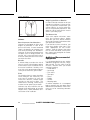
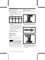
WARNING
Disregarding any of the safety precautions and instructions contained in
this Operator’s Guide, SAFETY DVD and on-product safety labels could
cause injury including the possibility of death!
WARNING
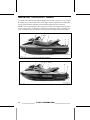
This watercraft may exceed the performance of other boats you may have
ridden in the past. Take time to familiarize yourself with your new watercraft.
CALIFORNIA PROPOSITION 65 WARNING
WARNING
This product contains or emits chemicals known to the state of California to
cause cancer and birth defects or other reproductive harm.
In Canada, products are distributed by Bombardier Recreational Products Inc.
(BRP).
In USA, products are distributed by BRP US Inc.
Knight’s Spray-Nine† is a trademark of Korkay System Ltd.
GTX† is a trademark of Castrol Ltd. Used under license.
This is a non-exhaustive list of trademarks that are the property of Bombardier
Recreational Products Inc. or its affiliates:
4-TECTM
O.T.A.S.TM
T.O.P.S.TM
D.E.S.S.TM
Rotax®
VTSTM
iBRTM
RXT®
XPSTM
iControlTM
Sea-Doo®
iSTM
Sea-Doo LKTM
iTCTM
S³HullTM
smo2010-002 en JL
®™ and the BRP logo are trademarks of Bombardier Recreational Products Inc. or its affiliates.
©2009 Bombardier Recreational Products Inc. and BRP US Inc. All rights reserved.
FOREWORD
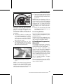
Congratulations on your purchase
of a new Sea-Doo® personal watercraft (PWC). It is backed by the BRP
warranty and a network of authorized
Sea-Doo personal watercraft dealers
ready to provide the parts, service or
accessories you may require.
Your dealer is committed to your satisfaction. He has taken training to perform the initial setup and inspection of
your watercraft as well as completed
the final adjustment before you took
possession. If you need more complete servicing information, please ask
your dealer.
At delivery, you were also informed of
the warranty coverage and signed the
PREDELIVERY CHECK LIST to ensure
your new watercraft was prepared to
your entire satisfaction.
Know Before you Go
To learn how to reduce the risk for you
or other persons being injured or killed,
read the following sections before you
operate the watercraft:
– SAFETY INFORMATION
– WATERCRAFT INFORMATION.
Read and understand all safety labels
on your watercraft and watch attentively your SAFETY DVD.
Failure to follow the warnings contained in this Operators' Guide can
result in serious injury or death.
BRP highly recommends that you take
a safe boating course. Please check
with your dealer or local authorities for
availability in your area.
In certain areas, an operator competency card is mandatory to operate a
pleasure craft.
Safety Messages
This Operator’s Guide utilizes the following symbols and words to emphasize particular information:
WARNING
Indicates a potential hazard which,
if not avoided, could result in serious injury or death.
CAUTION Indicates a potentially hazardous situation which, if
not avoided, could result in minor or
moderate injury.
NOTICE Indicates an instruction
which, if not followed, could severely damage watercraft components or other property.
About this Operator's
Guide
This Operator's Guide has been prepared to acquaint the owner/operator
or passenger with this personal watercraft and its various controls, maintenance and safe riding instructions.
Keep this Operators' Guide in the watercraft as you can refer to it for things
such as maintenance, troubleshooting
and instructing others.
Note that this guide is available in several languages. In the event of any discrepancy, the English version shall prevail.
If you want to view and/or print an
extra copy of your Operator's Guide,
simply visit the following website
www.operatorsguide.brp.com.
The informations contained in this document are correct at the time of publication. However, BRP maintains a policy of continuous improvement of its
products without imposing upon itself
any obligation to install them on products previously manufactured. Due
to late changes, some differences between the manufactured product and
the descriptions and/or specifications
in this guide may occur. BRP reserves
the right at any time to discontinue or
_______________
1
FOREWORD
change specifications, designs, features, models or equipment without
incurring any obligation upon itself.
This Operator's Guide and the SAFETY
DVD should remain with the watercraft
when it's sold.
2
_______________
TABLE OF CONTENTS
FOREWORD . . . . . . . . . . . . . . . . . . . . . . . . . . . . . . . . . . . . . . . . . . . . . . . . . . . . . . . . . . . . . . . . . . . . . . . . . .
Know Before you Go . . . . . . . . . . . . . . . . . . . . . . . . . . . . . . . . . . . . . . . . . . . . . . . . . . . . . . . . . . . . .
Safety Messages. . . . . . . . . . . . . . . . . . . . . . . . . . . . . . . . . . . . . . . . . . . . . . . . . . . . . . . . . . . . . . . . .
About this Operator's Guide . . . . . . . . . . . . . . . . . . . . . . . . . . . . . . . . . . . . . . . . . . . . . . . . . . . .
1
1
1
1
SAFETY INFORMATION
GENERAL PRECAUTIONS. . . . . . . . . . . . . . . . . . . . . . . . . . . . . . . . . . . . . . . . . . . . . . . . . . . . . . . . . .
Avoid Carbon Monoxide Poisoning . . . . . . . . . . . . . . . . . . . . . . . . . . . . . . . . . . . . . . . . . . . . .
Avoid Gasoline Fires and Other Hazards . . . . . . . . . . . . . . . . . . . . . . . . . . . . . . . . . . . . . . .
Avoid Burns from Hot Parts . . . . . . . . . . . . . . . . . . . . . . . . . . . . . . . . . . . . . . . . . . . . . . . . . . . . .
Accessories and Modifications . . . . . . . . . . . . . . . . . . . . . . . . . . . . . . . . . . . . . . . . . . . . . . . . .
SPECIAL SAFETY MESSAGES . . . . . . . . . . . . . . . . . . . . . . . . . . . . . . . . . . . . . . . . . . . . . . . . . . . .
Reminders Regarding Safe Operation. . . . . . . . . . . . . . . . . . . . . . . . . . . . . . . . . . . . . . . . . .
Water Sports (Towing with the Watercraft) . . . . . . . . . . . . . . . . . . . . . . . . . . . . . . . . . . .
Hypothermia. . . . . . . . . . . . . . . . . . . . . . . . . . . . . . . . . . . . . . . . . . . . . . . . . . . . . . . . . . . . . . . . . . . . .
Safe Boating Courses. . . . . . . . . . . . . . . . . . . . . . . . . . . . . . . . . . . . . . . . . . . . . . . . . . . . . . . . . . .
ACTIVE TECHNOLOGIES (iCONTROL) . . . . . . . . . . . . . . . . . . . . . . . . . . . . . . . . . . . . . . . . . .
Introduction. . . . . . . . . . . . . . . . . . . . . . . . . . . . . . . . . . . . . . . . . . . . . . . . . . . . . . . . . . . . . . . . . . . . . .
iTC (intelligent Throttle Control) . . . . . . . . . . . . . . . . . . . . . . . . . . . . . . . . . . . . . . . . . . . . . . . .
iBR (intelligent Brake and Reverse System) . . . . . . . . . . . . . . . . . . . . . . . . . . . . . . . . . .
iS (intelligent Suspension) . . . . . . . . . . . . . . . . . . . . . . . . . . . . . . . . . . . . . . . . . . . . . . . . . . . . . .
SAFETY EQUIPMENT . . . . . . . . . . . . . . . . . . . . . . . . . . . . . . . . . . . . . . . . . . . . . . . . . . . . . . . . . . . . . .
Required Safety Equipment . . . . . . . . . . . . . . . . . . . . . . . . . . . . . . . . . . . . . . . . . . . . . . . . . . . .
Additional Recommended Equipment . . . . . . . . . . . . . . . . . . . . . . . . . . . . . . . . . . . . . . . .
NAVIGATION RULES. . . . . . . . . . . . . . . . . . . . . . . . . . . . . . . . . . . . . . . . . . . . . . . . . . . . . . . . . . . . . . .
Operating Rules . . . . . . . . . . . . . . . . . . . . . . . . . . . . . . . . . . . . . . . . . . . . . . . . . . . . . . . . . . . . . . . . .
FUELING . . . . . . . . . . . . . . . . . . . . . . . . . . . . . . . . . . . . . . . . . . . . . . . . . . . . . . . . . . . . . . . . . . . . . . . . . . . . .
Fueling Procedure. . . . . . . . . . . . . . . . . . . . . . . . . . . . . . . . . . . . . . . . . . . . . . . . . . . . . . . . . . . . . . .
Recommended Fuel . . . . . . . . . . . . . . . . . . . . . . . . . . . . . . . . . . . . . . . . . . . . . . . . . . . . . . . . . . . .
TRAILERING INFORMATION . . . . . . . . . . . . . . . . . . . . . . . . . . . . . . . . . . . . . . . . . . . . . . . . . . . . .
IMPORTANT ON-PRODUCT LABELS . . . . . . . . . . . . . . . . . . . . . . . . . . . . . . . . . . . . . . . . . . . .
PRE-RIDE INSPECTION . . . . . . . . . . . . . . . . . . . . . . . . . . . . . . . . . . . . . . . . . . . . . . . . . . . . . . . . . . . .
What to Do Before Launching the Watercraft . . . . . . . . . . . . . . . . . . . . . . . . . . . . . . . .
What to Do After Launching the Watercraft . . . . . . . . . . . . . . . . . . . . . . . . . . . . . . . . . .
8
8
8
8
8
9
9
14
16
16
17
17
17
18
19
20
20
22
23
23
26
26
26
28
30
35
35
39
WATERCRAFT INFORMATION
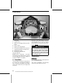
CONTROLS . . . . . . . . . . . . . . . . . . . . . . . . . . . . . . . . . . . . . . . . . . . . . . . . . . . . . . . . . . . . . . . . . . . . . . . . . .
1) Handlebar . . . . . . . . . . . . . . . . . . . . . . . . . . . . . . . . . . . . . . . . . . . . . . . . . . . . . . . . . . . . . . . . . . . . .
2) Throttle Lever. . . . . . . . . . . . . . . . . . . . . . . . . . . . . . . . . . . . . . . . . . . . . . . . . . . . . . . . . . . . . . . . .
3) iBR Lever (intelligent Brake and Reverse) . . . . . . . . . . . . . . . . . . . . . . . . . . . . . . . . . .
4) D.E.S.S. Post (Emergency Engine Stop Switch) . . . . . . . . . . . . . . . . . . . . . . . . . . .
5) Engine Start/Stop Button . . . . . . . . . . . . . . . . . . . . . . . . . . . . . . . . . . . . . . . . . . . . . . . . . . . .
42
42
44
48
49
52
_______________
3
TABLE OF CONTENTS
CONTROLS (cont’d)
6) VTS Button (Variable Trim System). . . . . . . . . . . . . . . . . . . . . . . . . . . . . . . . . . . . . . . . . .
7) iS Button (intelligent Suspension). . . . . . . . . . . . . . . . . . . . . . . . . . . . . . . . . . . . . . . . . . .
8) MODE/SET Button . . . . . . . . . . . . . . . . . . . . . . . . . . . . . . . . . . . . . . . . . . . . . . . . . . . . . . . . . . .
9) UP and DOWN Arrow Button . . . . . . . . . . . . . . . . . . . . . . . . . . . . . . . . . . . . . . . . . . . . . . .
10) Cruise Button. . . . . . . . . . . . . . . . . . . . . . . . . . . . . . . . . . . . . . . . . . . . . . . . . . . . . . . . . . . . . . . .
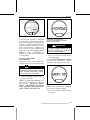
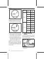
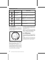
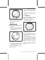
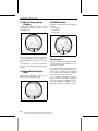
INFORMATION CENTER (GAUGE) . . . . . . . . . . . . . . . . . . . . . . . . . . . . . . . . . . . . . . . . . . . . . . .
1) Speedometer . . . . . . . . . . . . . . . . . . . . . . . . . . . . . . . . . . . . . . . . . . . . . . . . . . . . . . . . . . . . . . . . .
2) Tachometer . . . . . . . . . . . . . . . . . . . . . . . . . . . . . . . . . . . . . . . . . . . . . . . . . . . . . . . . . . . . . . . . . . .
3) Digital Screen . . . . . . . . . . . . . . . . . . . . . . . . . . . . . . . . . . . . . . . . . . . . . . . . . . . . . . . . . . . . . . . . .
4) Indicator Lights . . . . . . . . . . . . . . . . . . . . . . . . . . . . . . . . . . . . . . . . . . . . . . . . . . . . . . . . . . . . . . .
5) Fuel Level . . . . . . . . . . . . . . . . . . . . . . . . . . . . . . . . . . . . . . . . . . . . . . . . . . . . . . . . . . . . . . . . . . . . .
6) VTS Position . . . . . . . . . . . . . . . . . . . . . . . . . . . . . . . . . . . . . . . . . . . . . . . . . . . . . . . . . . . . . . . . . .
7) iS Position . . . . . . . . . . . . . . . . . . . . . . . . . . . . . . . . . . . . . . . . . . . . . . . . . . . . . . . . . . . . . . . . . . . . .
8) Numerical Display . . . . . . . . . . . . . . . . . . . . . . . . . . . . . . . . . . . . . . . . . . . . . . . . . . . . . . . . . . . .
9) Multifunction Display . . . . . . . . . . . . . . . . . . . . . . . . . . . . . . . . . . . . . . . . . . . . . . . . . . . . . . . .
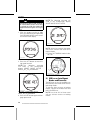
10) Depth Sounder Indicator . . . . . . . . . . . . . . . . . . . . . . . . . . . . . . . . . . . . . . . . . . . . . . . . . . .
11) Water Temperature Display . . . . . . . . . . . . . . . . . . . . . . . . . . . . . . . . . . . . . . . . . . . . . . .
12) Hour Meter Display (HR) . . . . . . . . . . . . . . . . . . . . . . . . . . . . . . . . . . . . . . . . . . . . . . . . . . .
13) iBR Position . . . . . . . . . . . . . . . . . . . . . . . . . . . . . . . . . . . . . . . . . . . . . . . . . . . . . . . . . . . . . . . . .
14) Compass. . . . . . . . . . . . . . . . . . . . . . . . . . . . . . . . . . . . . . . . . . . . . . . . . . . . . . . . . . . . . . . . . . . . .
15) Touring Mode Indicator . . . . . . . . . . . . . . . . . . . . . . . . . . . . . . . . . . . . . . . . . . . . . . . . . . . . .
16) Sport Mode Indicator . . . . . . . . . . . . . . . . . . . . . . . . . . . . . . . . . . . . . . . . . . . . . . . . . . . . . . .
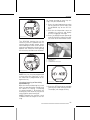
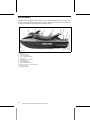
EQUIPMENT. . . . . . . . . . . . . . . . . . . . . . . . . . . . . . . . . . . . . . . . . . . . . . . . . . . . . . . . . . . . . . . . . . . . . . . . .
1) Glove Box . . . . . . . . . . . . . . . . . . . . . . . . . . . . . . . . . . . . . . . . . . . . . . . . . . . . . . . . . . . . . . . . . . . . .
2) Front Storage Bin . . . . . . . . . . . . . . . . . . . . . . . . . . . . . . . . . . . . . . . . . . . . . . . . . . . . . . . . . . . . .
3) Rear Storage Bins . . . . . . . . . . . . . . . . . . . . . . . . . . . . . . . . . . . . . . . . . . . . . . . . . . . . . . . . . . . .
4) Fire Extinguisher Holder . . . . . . . . . . . . . . . . . . . . . . . . . . . . . . . . . . . . . . . . . . . . . . . . . . . . .
5) Seat Latch. . . . . . . . . . . . . . . . . . . . . . . . . . . . . . . . . . . . . . . . . . . . . . . . . . . . . . . . . . . . . . . . . . . . .
6) Passenger Handholds. . . . . . . . . . . . . . . . . . . . . . . . . . . . . . . . . . . . . . . . . . . . . . . . . . . . . . . .
7) Boarding Step. . . . . . . . . . . . . . . . . . . . . . . . . . . . . . . . . . . . . . . . . . . . . . . . . . . . . . . . . . . . . . . . .
8) Boarding Platform . . . . . . . . . . . . . . . . . . . . . . . . . . . . . . . . . . . . . . . . . . . . . . . . . . . . . . . . . . . .
9) Speed-Ties . . . . . . . . . . . . . . . . . . . . . . . . . . . . . . . . . . . . . . . . . . . . . . . . . . . . . . . . . . . . . . . . . . . .
10) Front and Rear Eyelets . . . . . . . . . . . . . . . . . . . . . . . . . . . . . . . . . . . . . . . . . . . . . . . . . . . . .
11) Mooring Cleats . . . . . . . . . . . . . . . . . . . . . . . . . . . . . . . . . . . . . . . . . . . . . . . . . . . . . . . . . . . . . .
12) Bilge Drain Plugs . . . . . . . . . . . . . . . . . . . . . . . . . . . . . . . . . . . . . . . . . . . . . . . . . . . . . . . . . . . .
13) Ski/Wakeboard Post . . . . . . . . . . . . . . . . . . . . . . . . . . . . . . . . . . . . . . . . . . . . . . . . . . . . . . . .
14) Wakeboard Rack . . . . . . . . . . . . . . . . . . . . . . . . . . . . . . . . . . . . . . . . . . . . . . . . . . . . . . . . . . . .
OPERATING INSTRUCTIONS. . . . . . . . . . . . . . . . . . . . . . . . . . . . . . . . . . . . . . . . . . . . . . . . . . . . .
Operation During Break-In Period. . . . . . . . . . . . . . . . . . . . . . . . . . . . . . . . . . . . . . . . . . . . . .
Boarding the Watercraft . . . . . . . . . . . . . . . . . . . . . . . . . . . . . . . . . . . . . . . . . . . . . . . . . . . . . . . .
How to Start Engine. . . . . . . . . . . . . . . . . . . . . . . . . . . . . . . . . . . . . . . . . . . . . . . . . . . . . . . . . . . . .
How to Shut Off the Engine . . . . . . . . . . . . . . . . . . . . . . . . . . . . . . . . . . . . . . . . . . . . . . . . . . . .
How to Steer Watercraft . . . . . . . . . . . . . . . . . . . . . . . . . . . . . . . . . . . . . . . . . . . . . . . . . . . . . . .
How to Engage Neutral . . . . . . . . . . . . . . . . . . . . . . . . . . . . . . . . . . . . . . . . . . . . . . . . . . . . . . . . .
How to Engage Forward. . . . . . . . . . . . . . . . . . . . . . . . . . . . . . . . . . . . . . . . . . . . . . . . . . . . . . . .
How to Engage and Use Reverse. . . . . . . . . . . . . . . . . . . . . . . . . . . . . . . . . . . . . . . . . . . . . .
4
_______________
53
56
57
57
58
59
61
61
61
61
62
62
63
64
66
69
70
70
70
70
71
71
72
73
73
75
76
76
76
76
77
77
80
80
80
80
81
84
84
84
87
88
89
89
90
90
TABLE OF CONTENTS
OPERATING INSTRUCTIONS (cont’d)
How to Engage and Use Braking. . . . . . . . . . . . . . . . . . . . . . . . . . . . . . . . . . . . . . . . . . . . . . . 91
How to Use the Variable Trim System (VTS) . . . . . . . . . . . . . . . . . . . . . . . . . . . . . . . . . . 92
How to Use Cruise Mode. . . . . . . . . . . . . . . . . . . . . . . . . . . . . . . . . . . . . . . . . . . . . . . . . . . . . . . 93
How to Use Slow Speed Mode . . . . . . . . . . . . . . . . . . . . . . . . . . . . . . . . . . . . . . . . . . . . . . . . 94
Ski Mode . . . . . . . . . . . . . . . . . . . . . . . . . . . . . . . . . . . . . . . . . . . . . . . . . . . . . . . . . . . . . . . . . . . . . . . . . 96
iS (intelligent Suspension) Operation. . . . . . . . . . . . . . . . . . . . . . . . . . . . . . . . . . . . . . . . . . 99
General Recommendations . . . . . . . . . . . . . . . . . . . . . . . . . . . . . . . . . . . . . . . . . . . . . . . . . . 102
SPECIAL PROCEDURES . . . . . . . . . . . . . . . . . . . . . . . . . . . . . . . . . . . . . . . . . . . . . . . . . . . . . . . . . 105
Jet Pump Water Intake and Impeller Cleaning. . . . . . . . . . . . . . . . . . . . . . . . . . . . . . 105
Capsized Watercraft . . . . . . . . . . . . . . . . . . . . . . . . . . . . . . . . . . . . . . . . . . . . . . . . . . . . . . . . . . 105
Submerged Watercraft . . . . . . . . . . . . . . . . . . . . . . . . . . . . . . . . . . . . . . . . . . . . . . . . . . . . . . . 106
Water-Flooded Engine . . . . . . . . . . . . . . . . . . . . . . . . . . . . . . . . . . . . . . . . . . . . . . . . . . . . . . . . 106
Towing the Watercraft in Water. . . . . . . . . . . . . . . . . . . . . . . . . . . . . . . . . . . . . . . . . . . . . . 107
MAINTENANCE INFORMATION
MAINTENANCE SCHEDULE . . . . . . . . . . . . . . . . . . . . . . . . . . . . . . . . . . . . . . . . . . . . . . . . . . . .
10-HOUR INSPECTION . . . . . . . . . . . . . . . . . . . . . . . . . . . . . . . . . . . . . . . . . . . . . . . . . . . . . . . . . .
MAINTENANCE PROCEDURES . . . . . . . . . . . . . . . . . . . . . . . . . . . . . . . . . . . . . . . . . . . . . . . .
Ignition Coils . . . . . . . . . . . . . . . . . . . . . . . . . . . . . . . . . . . . . . . . . . . . . . . . . . . . . . . . . . . . . . . . . . .
Engine Oil . . . . . . . . . . . . . . . . . . . . . . . . . . . . . . . . . . . . . . . . . . . . . . . . . . . . . . . . . . . . . . . . . . . . . .
Engine Coolant . . . . . . . . . . . . . . . . . . . . . . . . . . . . . . . . . . . . . . . . . . . . . . . . . . . . . . . . . . . . . . . .
Spark Plugs . . . . . . . . . . . . . . . . . . . . . . . . . . . . . . . . . . . . . . . . . . . . . . . . . . . . . . . . . . . . . . . . . . . .
Ignition Coils . . . . . . . . . . . . . . . . . . . . . . . . . . . . . . . . . . . . . . . . . . . . . . . . . . . . . . . . . . . . . . . . . . .
Exhaust System . . . . . . . . . . . . . . . . . . . . . . . . . . . . . . . . . . . . . . . . . . . . . . . . . . . . . . . . . . . . . . .
Ride Plate and Water Intake Grate . . . . . . . . . . . . . . . . . . . . . . . . . . . . . . . . . . . . . . . . . . .
Jet Pump, Nozzle and iBR Gate . . . . . . . . . . . . . . . . . . . . . . . . . . . . . . . . . . . . . . . . . . . . . .
Ski/Wakeboard Post (Wake). . . . . . . . . . . . . . . . . . . . . . . . . . . . . . . . . . . . . . . . . . . . . . . . . .
Fuses. . . . . . . . . . . . . . . . . . . . . . . . . . . . . . . . . . . . . . . . . . . . . . . . . . . . . . . . . . . . . . . . . . . . . . . . . . .
WATERCRAFT CARE . . . . . . . . . . . . . . . . . . . . . . . . . . . . . . . . . . . . . . . . . . . . . . . . . . . . . . . . . . . . .
Post-Operation Care . . . . . . . . . . . . . . . . . . . . . . . . . . . . . . . . . . . . . . . . . . . . . . . . . . . . . . . . . .
Watercraft Cleaning. . . . . . . . . . . . . . . . . . . . . . . . . . . . . . . . . . . . . . . . . . . . . . . . . . . . . . . . . . .
STORAGE AND PRESEASON PREPARATION . . . . . . . . . . . . . . . . . . . . . . . . . . . . . . . .
Storage. . . . . . . . . . . . . . . . . . . . . . . . . . . . . . . . . . . . . . . . . . . . . . . . . . . . . . . . . . . . . . . . . . . . . . . . .
Preseason Preparation . . . . . . . . . . . . . . . . . . . . . . . . . . . . . . . . . . . . . . . . . . . . . . . . . . . . . . .
110
114
115
115
116
118
119
120
121
122
122
124
125
127
127
127
128
128
130
TECHNICAL INFORMATION
WATERCRAFT IDENTIFICATION . . . . . . . . . . . . . . . . . . . . . . . . . . . . . . . . . . . . . . . . . . . . . . .
Hull Identification Number . . . . . . . . . . . . . . . . . . . . . . . . . . . . . . . . . . . . . . . . . . . . . . . . . . .
Engine Identification Number . . . . . . . . . . . . . . . . . . . . . . . . . . . . . . . . . . . . . . . . . . . . . . . .
EPA Compliance Label. . . . . . . . . . . . . . . . . . . . . . . . . . . . . . . . . . . . . . . . . . . . . . . . . . . . . . . .
ENGINE EMISSIONS INFORMATION. . . . . . . . . . . . . . . . . . . . . . . . . . . . . . . . . . . . . . . . . .
Manufacturer's Responsibility . . . . . . . . . . . . . . . . . . . . . . . . . . . . . . . . . . . . . . . . . . . . . . .
132
132
132
132
134
134
_______________
5
TABLE OF CONTENTS
ENGINE EMISSIONS INFORMATION (cont’d)
Dealer's Responsibility . . . . . . . . . . . . . . . . . . . . . . . . . . . . . . . . . . . . . . . . . . . . . . . . . . . . . . .
Owner Responsibility . . . . . . . . . . . . . . . . . . . . . . . . . . . . . . . . . . . . . . . . . . . . . . . . . . . . . . . . .
EPA Emission Regulations . . . . . . . . . . . . . . . . . . . . . . . . . . . . . . . . . . . . . . . . . . . . . . . . . . .
SPECIFICATIONS . . . . . . . . . . . . . . . . . . . . . . . . . . . . . . . . . . . . . . . . . . . . . . . . . . . . . . . . . . . . . . . . .
134
134
134
135
TROUBLESHOOTING
TROUBLESHOOTING GUIDELINES . . . . . . . . . . . . . . . . . . . . . . . . . . . . . . . . . . . . . . . . . . .
MONITORING SYSTEM . . . . . . . . . . . . . . . . . . . . . . . . . . . . . . . . . . . . . . . . . . . . . . . . . . . . . . . . .
Fault Codes . . . . . . . . . . . . . . . . . . . . . . . . . . . . . . . . . . . . . . . . . . . . . . . . . . . . . . . . . . . . . . . . . . . .
Indicator Lights and Message Display Information. . . . . . . . . . . . . . . . . . . . . . . . .
Beeper Code Information . . . . . . . . . . . . . . . . . . . . . . . . . . . . . . . . . . . . . . . . . . . . . . . . . . . .
142
146
146
147
149
WARRANTY
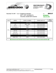
BRP LIMITED WARRANTY – USA AND CANADA: 2010 SEA-DOO® PERSONAL
WATERCRAFT . . . . . . . . . . . . . . . . . . . . . . . . . . . . . . . . . . . . . . . . . . . . . . . . . . . . . . . . . . . . . . . . . . . . 152
CALIFORNIA AND NEW YORK EMISSION CONTROL WARRANTY
STATEMENT FOR MODEL YEAR 2010 SEA-DOO® PERSONAL WATERCRAFT
WITH 4-TEC® ENGINES . . . . . . . . . . . . . . . . . . . . . . . . . . . . . . . . . . . . . . . . . . . . . . . . . . . . . . . . . . 156
BRP INTERNATIONAL LIMITED WARRANTY: 2010 SEA-DOO® PERSONAL
WATERCRAFT. . . . . . . . . . . . . . . . . . . . . . . . . . . . . . . . . . . . . . . . . . . . . . . . . . . . . . . . . . . . . . . . . . . . . 160
BRP LIMITED WARRANTY FOR THE EUROPEAN ECONOMIC AREA: 2010
SEA-DOO® PERSONAL WATERCRAFT. . . . . . . . . . . . . . . . . . . . . . . . . . . . . . . . . . . . . . . . 164
CUSTOMER INFORMATION
PRIVACY INFORMATION . . . . . . . . . . . . . . . . . . . . . . . . . . . . . . . . . . . . . . . . . . . . . . . . . . . . . . . . 170
CHANGE OF ADDRESS/OWNERSHIP. . . . . . . . . . . . . . . . . . . . . . . . . . . . . . . . . . . . . . . . . 171
6
_______________
SAFETY
INFORMATION
________
SAFETY INFORMATION
________
7
GENERAL PRECAUTIONS
Avoid Carbon Monoxide
Poisoning
All engine exhaust contains carbon
monoxide, a deadly gas. Breathing carbon monoxide can cause headaches,
dizziness, drowsiness, nausea, confusion and eventually death.
Carbon monoxide is a colorless, odorless, tasteless gas that may be present
even if you do not see or smell any engine exhaust. Deadly levels of carbon
monoxide can collect rapidly, and you
can quickly be overcome and unable
to save yourself. Also, deadly levels of
carbon monoxide can linger for hours
or days in enclosed or poorly ventilated
areas. If you experience any symptoms of carbon monoxide poisoning,
leave the area immediately, get fresh
air and seek medical treatment.
To prevent serious injury or death from
carbon monoxide:
– Never run the watercraft in poorly
ventilated or partially enclosed areas such as boat houses, seawalls
or other boats in close proximity.
Even if you try to ventilate engine
exhaust, carbon monoxide can
rapidly reach dangerous levels.
– Never run the watercraft outdoors
where engine exhaust can be drawn
into a building through openings
such as windows and doors.
– Never stand behind the watercraft
while the engine is running. A person standing behind a running engine may inhale high concentrations
of exhaust fumes. Inhalation of concentrated exhaust fumes that contain carbon monoxide can result in
CO poisoning, serious health problems and death.
Avoid Gasoline Fires and
Other Hazards
Gasoline is extremely flammable and
highly explosive. Fuel vapors can
spread and be ignited by a spark or
8
________
flame many feet away from the engine. To reduce the risk of fire or explosion, follow these instructions:
– Use only an approved red gasoline
container to store fuel.
– Strictly adhere to the instructions in
FUELING section.
– Never start watercraft if gasoline or
gasoline vapor odors is present in
the engine compartment.
– Never start or operate the engine if
the fuel cap is not properly latched.
– Do not carry gasoline containers in
the front storage compartment or
anywhere else on the watercraft.
Gasoline is poisonous and can cause
injury or death.
– Never siphon gasoline with your
mouth.
– If you swallow gasoline, get any in
your eyes, or inhale gasoline vapors,
see a doctor immediately.
If gasoline is spilled on you, wash
thoroughly with soap and water and
change your clothes.
Avoid Burns from Hot Parts
The ride plate, exhaust system and
engine become hot during operation.
Avoid contact during and shortly after
operation to avoid burns.
Accessories and
Modifications
Do not make unauthorized modifications, or use accessories that are not
approved by BRP. Since these changes
have not been tested by BRP, they
may increase the risk of accidents or
injuries, and they can make the watercraft illegal for use on water.
See your authorized Sea-Doo dealer
for available accessories for your watercraft.
SAFETY INFORMATION
________
SPECIAL SAFETY MESSAGES
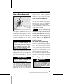
Reminders Regarding Safe
Operation
– The performance of this watercraft
may significantly exceed that of
other watercrafts you may have
operated. Make sure you read and
understand the content of this Operators Guide to become completely
familiar with the controls and operation of the watercraft before embarking on your first trip, or taking on
a passenger(s). If you have not had
the opportunity to do so, practice
driving solo in a suitable traffic free
area to become accustomed to the
feel and response of each control.
Be fully familiar with all controls before accelerating above idle speed.
Do not assume that all PWCs handle identically. Each model differs,
often substantially.
– Always keep in mind that as the
throttle lever is returned to the idle
position, less directional control is
available. To turn the watercraft,
both steering and throttle are necessary. If the engine is shut off, directional control is lost.
– Although most watercrafts have no
means of braking, advancement in
technologies now permit us to offer models that are equipped with
a braking system called the iBRTM
system. Practice braking maneuvers in a safe traffic-free area to become familiar with handling under
braking and with stopping distances
under various operating conditions.
________
WARNING
Stopping distance will vary depending on initial speed, load,
wind, number of riders and water
conditions. The amount of braking
power commanded by the operator using the iBR lever (intelligent
Brake and Reverse) will also affect
stopping distance.
– When braking, riders must brace
themselves against the deceleration force to prevent from moving
forward on the watercraft and losing balance.
– When operating an iBR equipped
watercraft, be aware that other
boats following or operating in close
proximity may not be able to stop as
quickly.
– When at speed and the brake is first
applied, a plume of water will shoot
up in the air behind the watercraft
which may cause the operator of a
following watercraft to momentarily
loose sight of your PWC. It is important to inform the operator of a
watercraft who intends to follow in
a convoy formation, of the braking
and maneuvering capability of your
PWC, what the plume of water indicates, and that a greater distance
should be maintained between watercrafts.
– When actuating the iBR control
lever while the watercraft has some
forward speed, the braking mode
will engage and generate a deceleration proportional to the iBR lever
position. The more you pull in the
iBR lever, the greater the braking
force becomes. Be careful to gradually actuate the iBR lever to adjust
the intensity of the braking force,
and to simultaneously release the
throttle lever.
– Do not release throttle to steer.
SAFETY INFORMATION
________
9
SPECIAL SAFETY MESSAGES
WARNING
Do not release the throttle when
trying to steer away from objects
without the use of the braking system. Engine power and jet pump
thrust is required to steer the watercraft.
– The brake feature of the iBR system
cannot prevent your PWC from drifting due to current or wind. It has no
braking effect on the rearward velocity. Also note that your engine
must be running to be able to use
the brake.
– The personal watercrafts' jet thrust
can cause injury. The jet pump may
pick up debris and throw it rearward
causing a risk of injuring people,
damaging the jet pump, or other
property.
– Observe the instructions on all
safety labels. They are there to help
assure that you have a safe and enjoyable outing.
– Do not store any objects in areas
that are not designed specifically for
storage.
– Riding with passenger(s), pulling
tubes, a skier, or a wake boarder
makes the PWC handle differently
and requires greater skill.
– Certain PWC models come
equipped with tow eyelets or a
ski pole which, can be used to attach a tow rope for a skier, tube or
wake boarder. Do not use these
attachment points or any other
portion of the watercraft to tow a
para-sail or any other craft. Personal
injury or severe damage may occur.
10
_______
– Combustion engines need air to
operate; consequently this PWC
cannot be totally watertight. Any
maneuvers such as turning constantly in tight circles, plunging the
bow through waves, or capsizing
the watercraft, that cause the air inlet openings to be under water may
cause severe engine problems due
to water ingestion. Refer to HOW
TO STEER WATERCRAFT in the OPERATING INSTRUCTIONS section
and the WARRANTY section contained in this Operator's Guide.
– Engine exhaust contains carbon
monoxide (CO), which can cause
serious health problems or death
if inhaled in sufficient quantities.
Do not operate the PWC in a confined area or allow CO to accumulate around the PWC, or in enclosed
or sheltered areas such as when
docked, or when rafting. Be aware
of the risk of CO emanations from
exhaust of other PWCs.
– Know the waters in which the watercraft is to be operated. Current,
tides, rapids, hidden obstacles,
wakes and waves etc. can affect
safe operation. It is not advisable
to operate the watercraft in rough
waters or inclement weather.
– In shallow water, proceed with
caution and at very low speeds.
Grounding or abrupt stops may result in injury and watercraft damage.
Debris may also be picked up and
thrown rearward by the jet pump
onto people or property.
SAFETY INFORMATION
________
SPECIAL SAFETY MESSAGES
– Keep the safety lanyard attached
to the operators' PFD at all times
and keep it free from snagging on
the handlebars to help ensure the
engine stops should the operator
fall off. After riding, remove the
D.E.S.S.™ key from its post to avoid
unauthorized use by children or others. If the operator falls off the watercraft and the safety lanyard is not
attached as recommended, the watercraft engine will not stop.
– Ride within your limits and level of
riding ability.
WARNING
Avoid aggressive maneuvers to
reduce the risk of loss of control,
ejection and collision. Understand
and respect the performance of
your watercraft.
– Always ride responsibly and safely.
Use common sense and courtesy.
– Respect no wake zones, the environment, and the rights of other
users of the waterways. As the operator and owner of a PWC, you
are responsible for damage by the
wake of your PWC. Do not let anyone throw refuse overboard.
– While your watercraft has the capacity of operating at high speeds,
it is strongly recommended that
high speed operation only be applied when ideal conditions exist
and are permitted. Higher speed
operation requires a higher degree
of skill and increases the risk of severe injuries.
– The forces generated on the body
of riders while turning, negotiating waves or wakes, operating in
choppy waters, or falling off the watercraft, especially at higher speeds,
may cause injury including the possibility of broken bones or more serious bodily injuries. Remain flexible
and avoid sharp turns.
________
– PWCs are not designed for nighttime operation.
– Certain PWC models are equipped
with an intelligent suspension. Although the system absorbs part of
the vertical forces and therefore reduces the impact force to the body,
it cannot eliminate it completely. To
prevent you and your passenger(s)
from being bounced and eventually
be ejected from the watercraft, reduce your speed.
– Do not jump wakes or wakes.
WARNING
Avoid riding in very rough waters
or practicing extreme maneuvers
like jumping wakes or waves.
Before Getting Underway
– For safety reasons and proper care,
always perform the pre-ride inspection as specified in your Operators
Guide before operating your watercraft.
– Do not exceed the payload or passenger capacities for your watercraft, which are listed on the capacity plate and in the specifications.
Overloading can affect maneuverability, stability and performance.
Also, heavy seas reduce capacity. A
payload or person capacity plate is
not an excuse for failure to use common sense or good judgment.
– Regularly inspect the PWC, hull,
engine, safety equipment, and all
other boating gear and keep them in
safe operating condition.
– Be sure you have the minimum required safety equipment, PFDs and
any additional gear needed for your
cruise.
– Check that all lifesaving equipment,
including fire extinguisher, is in
safe operating condition and easily accessible. Show all passengers
where this equipment is stored on
the PWC, and make sure they know
how to use it.
SAFETY INFORMATION
________
11
SPECIAL SAFETY MESSAGES
– Keep an eye on the weather. Check
local weather broadcasts before departure. Be alert to changing conditions.
– Keep accurate and up-to-date charts
of the boating area on board. Before
getting underway, check water conditions in the planned boating area.
– Keep enough fuel on board for the
planned trip. Always verify fuel level
before use and during the ride. Apply the principle of 1/3 of the fuel to
reach your destination, 1/3 to return,
and keep 1/3 in reserve. Allow for
changes due to adverse weather or
other delays.
Operator and Passenger Awareness
– Read and understand all safety labels on the Sea-Doo PWC, the Operators Guide, all other safety documents, and watch the SAFETY DVD
before operating the PWC.
– Respect applicable laws.
WARNING
Check local and federal boating
laws applicable to the waterways
where you intend to use your watercraft. Learn the local navigation rules. Know and understand
the applicable navigation system
(such as buoys and signs).
– Remember that sun, wind, fatigue
or illness may impair your judgement and reaction time.
– Don't drink and drive.
WARNING
Never ride under the influence of
alcohol or drugs. They slow reaction time and impair judgment.
– Operation of this PWC by a person
under 16 years of age, or a person
with a disability that impairs vision,
reaction time, judgment, or operation of the controls is NOT recommended.
– Always use the safety lanyard when
operating the watercraft and ensure
that all passengers are familiar with
its use.
– Ensure that any operator and all passengers know how to swim and
how to re-board the PWC from
the water. Boarding in deep water can be strenuous. Practice in
chest-deep water before operating or embarking your watercraft
in deep water. If a passenger does
not know how to swim, ensure that
passenger wears a PFD at all times
and take extra precautions when
boating.
– Never turn handlebar while someone is near the rear of watercraft.
Keep away from steering moving
parts (nozzle, iBR gate, linkages,
etc.).
– Do not start the engine or operate
the watercraft if anyone is in the water nearby, or near the rear of the
watercraft.
WARNING
Do not start or operate the watercraft if anyone is nearby in the water.
– Be aware of the iBR gate movement
when starting the engine, shutting
down the engine or using the iBR
lever. Automatic movement of the
gate may squeeze fingers or toes of
people taking a hold on the back or
your PWC.
12
_______
SAFETY INFORMATION
________
SPECIAL SAFETY MESSAGES
– The operator and passenger(s)
should be properly seated and have
a firm grip on a handhold before
starting the watercraft, and at all
times when the watercraft is in motion. All passenger(s) should be instructed to use the handholds provided, or to hold on to the waist of
the person in front of them. Each
passenger must be able to simultaneously place both feet firmly flat
against each footwell when properly seated.
– When braking, riders must brace
themselves against the deceleration force to prevent from moving
forward on the watercraft and losing balance.
– When accelerating on a PWC with
a passenger(s), whether from a
complete stop or while underway,
always do so progressively. Fast
acceleration may cause your passenger(s) to loose their balance
and fall rearward off the watercraft.
Make sure that your passenger(s)
are aware of or can anticipate any
rapid acceleration.
– Keep away from intake grate.
WARNING
Keep away from the intake grate
while the engine is on. Items such
as long hair, loose clothing, or PFD
straps can become entangled in
moving parts.
– If the throttle lever is depressed
while braking, the iBR system will
disable the throttle command by
the user. When releasing the iBR
lever while the throttle lever is still
depressed, the throttle command
will regain control and generate an
acceleration after a short delay. Release throttle lever if acceleration is
not needed.
________
– Severe internal injuries can occur if
water is forced into body cavities as
a result of falling into water or being
near a jet thrust nozzle.
– Before reboarding, make sure engine is off and D.E.S.S. key is removed.
WARNING
To prevent accidental starting,
always detach the D.E.S.S. key
from its post when swimmers are
boarding or nearby, or during removal of any weeds or debris from
the intake grate.
– On a PWC, never place your feet
and legs in the water to aid turning.
Operation by Minors
Minors should always be supervised
by an adult whenever operating a watercraft. Laws regarding the minimum
age and licensing requirements of minors may vary from one jurisdiction to
another. Be sure to contact the local
boating authorities for information regarding the legal operation of a PWC in
the intended jurisdiction of use. BRP
recommends a minimum operator age
of 16 years old.
Drugs and Alcohol
Never operate your PWC under the
influence of alcohol or drugs. Like driving a car, driving a watercraft requires
the operator to be sober, attentive and
alert. Operating a watercraft while
intoxicated or under the influence of
drugs is not only dangerous, but it is
also a Federal offense carrying a significant penalty. These laws are vigorously enforced. The use of drugs and
alcohol, singly or in combination, decreases reaction time, impedes judgment, impairs vision, and inhibits your
ability to safely operate a watercraft.
SAFETY INFORMATION
________
13
SPECIAL SAFETY MESSAGES
WARNING
Alcohol consumption and boating
do not mix! Operating under the
influence endangers the lives of
your passengers, other boaters,
and yourself. Federal laws prohibit operating a watercraft under
the influence of alcohol or drugs.
Water Sports (Towing with
the Watercraft)
WARNING
Avoid personal injury! Your PWC
is not designed for and should not
be used for pulling another craft,
parasails, kites, gliders, or any device which can become airborne.
Use your watercraft only for water
sports it was designed for.
Water skiing, wakeboarding, or riding
a towed inflatable apparatus are some
of the more popular water sports. Taking part in any water sport requires
increased safety awareness by the participant and the watercraft operator. If
you have never towed someone behind your PWC before, it is a good idea
to spend some hours as an observer,
working with and learning from an experienced operator. It is also important
to be aware of the skill and experience
of the person being towed.
Everyone participating in a water sport
should observe these guidelines:
– Riding with passenger(s) or pulling
a tube, skier or wakeboarder makes
the watercraft handle differently
and requires greater skill.
– Always respect the safety and comfort of your passenger(s) and person
being towed on skis, wakeboard or
other water products.
14
_______
– Always carry an observer when
pulling a tube, skier or wakeboarder
to observe the person being towed
and inform the operator about the
participants' hand signals. The operator must focus his attention on
operating the watercraft and the
waters ahead.
– Proceed with only as much speed as
required and follow the observers'
instructions.
– When pulling a tube, skier, or a wake
boarder, do not make tight sharp
turns or use the braking system
unless absolutely necessary. Remember that although this PWC is
manoeuvrable and has stopping capabilities, the person in tow may not
be able to avoid an obstacle, or the
PWC with which it is being towed.
– Allow only capable swimmers to
take part in any water sport.
– Always wear an approved personal
flotation device (PFD). Wearing
a properly designed PFD helps a
stunned or unconscious person stay
afloat.
– Be considerate to others you share
the water with.
– Both the operator and observer
should monitor the location of the
tow rope when participating in watersports. A slack tow rope can become entangled with a person(s) or
objects on the PWC or in the water, particularly when making a tight
turn or circling, and cause serious
personal injury.
– Do not tow a person in any water
sport on a short tow rope such that
the person inhales exhaust fumes
in concentration. Inhalation of concentrated exhaust fumes, which
contain carbon monoxide, can result in CO poisoning, personal injury
and death.
SAFETY INFORMATION
________
SPECIAL SAFETY MESSAGES
– Use a tow rope of sufficient length
and size and make sure it is adequately secured to your watercraft. While some watercrafts are
equipped or can be fitted with a
specially designed towing mechanism, avoid installing a tow pole
on a PWC. It can become a hazard
should someone fall on it.
– Give immediate attention to a person who has fallen. He or she is
vulnerable in the water alone and
may not be seen by other boaters.
– Approach a person in the water from
the lee side (opposite the direction
of the wind). Turn off the motor before coming close to the person.
– Participate in water sports only
in safe areas. Stay away from
other boats, channels, beaches,
restricted areas, swimmers, and
heavily traveled waterways and underwater obstructions.
– Turn off the engine and anchor the
watercraft before swimming.
– Swim only in areas designated as
safe for swimming. These are usually marked with a swim area buoy.
Do not swim alone or at night.
– Do not drive the watercraft directly
behind a water skier, tuber or wakeboarder. At 40 km/h (25 MPH) per
hour, the watercraft will overtake a
person who falls in the water 60 m
(197 ft) in front of your watercraft in
about 5 seconds.
– Shut off the engine and remove the
D.E.S.S.TM key from its post (lanyard) when anyone is in the water
nearby.
– Stay at least 45 m (148 ft) away
from areas marked by a diver down
float.
WARNING
Avoid personal injury! Do not allow anyone near the propulsion
system or intake grate, even when
the engine is off. Items such as
long hair, loose clothing or personal flotation device straps can
become entangled in moving
parts resulting in serious injury
or drowning. In shallow water,
shells, sand, pebbles or other objects could be drawn up by the jet
pump and be thrown rearward.
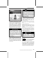
F00A2LY
SWIM AREA BUOY
– Do not water ski between sunset
and sunrise. It is illegal in most areas.
F00A2MY
DIVER DOWN FLOAT
For more information on approved, legal and safe practice of water sports,
please contact the local legal authority
on water sports safety for the area you
plan to practice in.
________
SAFETY INFORMATION
________
15
SPECIAL SAFETY MESSAGES
Hypothermia
Safe Boating Courses
Hypothermia, the loss of body heat
resulting in a subnormal body temperature, is a significant cause of death in
boating accidents. After an individual
has succumbed to hypothermia, he or
she will lose consciousness and then
drown.
PFDs can increase survival time because of the insulation they provide.
Naturally, the warmer the water, the
less insulation one will require. When
operating in cold water (below 4°C
(40°F)) consideration should be given
to using a coat or jacket style PFD as
they cover more body area than the
vest style PFDs.
Some points to remember about hypothermia protection:
– While afloat in the water, do not attempt to swim unless it is to reach
a nearby boat, fellow survivor, or a
floating object onto which you can
lean or climb. Unnecessary swimming increases the rate of body heat
loss. In cold water, drown-proof
methods that require putting your
head in the water are not recommended. Keep your head out of the
water. This will greatly lessen heat
loss and increase your survival time.
– Maintain a positive attitude about
your survival and rescue. This will
improve your chances of extending
your survival time until you can be
rescued. Your will to live does make
a difference!
– If there is more than one person
in the water, huddling together is
recommended. This action tends to
reduce the rate of heat loss and thus
increase the survival time.
– Always wear your PFD. It won't help
you fight off the effects of hypothermia if you don't have it on when you
go into the water.
Many countries recommend or require
a boating safety course. Check with
your local competent authorities.
Check local and federal boating laws
applicable to the waterways where
you intend to use your watercraft.
Learn the local navigation rules. Know
and understand the applicable navigation system (such as buoys and signs).
16
_______
SAFETY INFORMATION
________
ACTIVE TECHNOLOGIES (iCONTROL)
Introduction
NOTE: Some functions or features described in this section may not apply to
every PWC model, or may be available
as an option.
iControlTM (intelligent Control systems) provides an environment
whereby the operator can control
many systems without taking his
hands off the handlebars.
All controls are at the operator's finger
tips and activated by pressing a button
or pulling a lever. The operator's attention can thus remain focused on the
water and driving the watercraft.
Each control is electronic and provides
a command signal to an electronic
module whose function is to assure
proper operation of its system within
set parameters.
The various systems grouped under
iControl are the:
– iTCTM (intelligent Throttle Control)
– iBR (intelligent Brake and Reverse)
– iSTM (intelligent suspension)
– O.T.A.S. (Off Throttle Assisted
Steering).
These systems function together to
provide new features such as cruise
control, slow speed mode and braking,
improved watercraft response to operator inputs, increased maneuverability
and control.
It is extremely important for operators
to read all information contained in this
operator's guide so as to become familiar with this watercraft, its systems,
controls, capabilities and limitations.
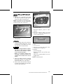
iTC (intelligent Throttle
Control)
The system uses an electronic throttle
control (ETC) that provides command
signals to the ECM (Engine Control
Module). With this system, there is no
need for a traditional throttle cable.
________
The iTC allows new functions such
as touring/sport mode, cruise control, slow speed mode, ski mode and
O.T.A.S.TM as well as a more precise
control of the engine power.
Touring/Sport Mode
Touring/Sport mode allows the operator to choose between sport mode
for instant throttle response, or touring mode for progressive throttle response at certain engine regimes.
In sport mode, maximum engine
power is available throughout the engine operational range.
In touring mode, available engine
power and acceleration is reduced
when accelerating from a complete
stop and when operating in the low
engine power range under certain conditions.
When throttle is applied in touring
mode, the engine will progressively
accelerate to an operating range
whereby full power eventually becomes available as if operating in sport
mode. If the engine is throttled down
sufficiently and for a long enough period of time, engine power and acceleration will again be reduced.
Cruise Control
Cruise control allows the operator
to set a desired maximum speed of
the watercraft when operating above
3800 RPM.
Cruise control limits watercraft speed
but does not maintain it. The operator must hold the throttle lever depressed to maintain forward speed,
unlike an automotive type cruise control which maintains a constant speed
while throttle pedal is released.
As you proceed under a constant cruising speed setting, hold the throttle
lever fully depressed in order to keep
your full attention to maintaining good
situational awareness.
SAFETY INFORMATION
________
17
ACTIVE TECHNOLOGIES (iCONTROL)
Slow Speed Mode
Slow speed mode is a function of
cruise control which allows the
operator to adjust and set idle
speed corresponding to a watercraft speed of 1.6 km/h to 8 km/h
(1 MPH to 5 MPH). The throttle lever
should not be depressed while operating in slow speed mode.
Ski Mode
Ski mode allows for a controlled launch
and accurately maintained maximum
towing speed when towing a skier or
wake boarder.
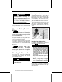
O.T.A.S. TM System
(Off-Throttle Assisted Steering)
The O.T.A.S. (Off-Throttle Assisted
Steering) system provides additional
maneuverability in off-throttle situations. The O.T.A.S. system is electronically activated and slightly increases engine speed under a preprogrammed RPM when the driver initiates a full turn. When handlebar is
brought back to its center position, the
throttle reverts to idle.
Limitations
The O.T.A.S. system cannot help you
maintain control or prevent collisions
in all situations.
Learning Key
The Sea-DooTM learning key can be
programmed to limit the speed of the
watercraft therefore enabling first time
users and less experienced operators
to learn how to operate the watercraft
while gaining the necessary confidence and control.
Limitations
The ability of a novice to operate the
watercraft can be exceeded even
when a learning key is used.
18
_______
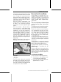
iBR (intelligent Brake and
Reverse System)
This watercraft uses an electronically
controlled braking and reverse system
called the iBR system (intelligent Brake
and Reverse).
The iBR module controls the position
of the iBR gate to provide forward
thrust, reverse thrust, braking thrust,
and neutral.
The operator commands the position
of the iBR gate using either the throttle lever for forward thrust, or the iBR
lever for neutral, reverse, and for the
braking function.
NOTE: The iBR lever can only be used
to command a change in the gate position if the engine is running.
Using the iBR system significantly reduces the stopping distance of this
watercraft and can increase its maneuverability as it can be used in a straight
line, in a turn, at high or low speeds, or
to propel the watercraft in reverse for
docking or maneuvering in very close
quarters.
Under ideal conditions, experienced
operators were consistently able to reduce by approximately 33%, the stopping distance of a watercraft equipped
with an iBR system from an initial
speed of 80 km/h (50 MPH).
Limitations
Even when equipped with an iBR system, watercrafts do not have the ability
of land based vehicles.
Stopping distance will vary notably depending on initial speed, load, wind,
current, water conditions and the
amount of braking.
The iBR system has no effect on the
rearward motion.
It cannot prevent your watercraft from
drifting in current or wind.
SAFETY INFORMATION
________
ACTIVE TECHNOLOGIES (iCONTROL)
iS (intelligent Suspension)
The suspension system of this watercraft is designed so that the occupants
sit on what is known as the moving
deck. When the suspension system is
active, the moving deck is usually in an
"up" position. This means the moving
deck is raised above the fixed deck sufficiently for the suspension system to
absorb the up and down movement of
the watercraft as it travels through the
water.
The iS system incorporates a function known as DOCK MODE. When
activated manually or automatically,
DOCK MODE moves the suspension
down to lower the center of gravity of
the watercraft. This function is useful
when transporting the watercraft, operating at slow speed or when O.T.A.S.
is activated as it reduces the possibility
of overturning.
Limitations
Although the system absorbs partially
the vertical forces transferred to the
occupants when riding, it cannot eliminate them completely. Sudden jolts
can cause the suspension to bottom.
________
SAFETY INFORMATION
________
19
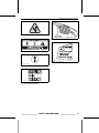
SAFETY EQUIPMENT
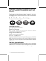
Required Safety
Equipment
The operator and the passenger(s)
must wear an approved Personal Flotation Device (PDF) that is suitable for
PWC use.
Operator and passenger(s) should
have ready access to shatterproof
glasses should riding conditions or
personal preference warrant.
Wind, water spray and speed may
cause a person's eyes to water and
create blurred vision.
As the owner of the watercraft, you
are responsible for assuring that all
required safety equipment is aboard.
You should also consider supplying additional equipment as needed for your
safety and that of your passengers.
Check state and local regulations about
required safety equipment.
Safety equipment required by regulations is mandatory. If local regulations
require additional equipment, it must
be approved by a competent authority.
Minimum requirements include the
following:
– Personal flotation devices (PFDs)
– A buoyant heaving line of 15 m
(50 ft) minimum
– A watertight flashlight or approved
flares
– Signaling device
– Sound producing devices (air horn or
whistle).
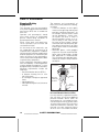
The operator and passenger(s) of
PWCs must wear protective clothing,
including:
– A wet suit bottom, or thick tightly
woven and snug fitting clothing that
provides equivalent protection. As
an example, thin bike shorts would
not be appropriate. Severe internal injuries can occur if water is
forced into body cavities as a result of falling in the water or being near jet thrust nozzle. Normal
swimwear does not adequately protect against forceful entry of water
into the lower male or female body
opening(s).
– Footwear, gloves, safety goggles
or glasses are also recommended.
Some type of lightweight, flexible
foot protection is recommended.
This will help reduce possible injury,
should you step on sharp underwater objects.
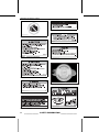
Eye
protection
Wet suit
or wet suit
bottom
Vest-type
personal
flotation
device
Gloves
Foot
protection
F00A12A
Personal Flotation Devices (PFDs)
In many countries, regulations require
that you have at least one approved
personal flotation device (PFD) for
each person on a recreational watercraft and require that all children under
13 years of age wear a PFD at all times
when the watercraft is underway. You
may not use your watercraft unless
all PFDs are in serviceable condition,
20
_______
SAFETY INFORMATION
________
SAFETY EQUIPMENT
readily accessible, legibly marked with
the approval number, and of an appropriate size (within the weight range and
chest size marked on the PFD) for each
person on board.
A PFD provides buoyancy to help keep
the head and face above the water, and
to help maintain a satisfactory body position while in the water. Body weight
and age should be considered when
selecting a PFD. The buoyancy provided by the PFD should support your
weight in water. The size of the PFD
should be appropriate for the wearer.
Body weight and chest size are common methods used to size PFDs. It is
your responsibility to ensure that you
have the proper number and types of
PFDs on board to comply with federal
and local regulations, and that your
passengers know where they are and
how to use them.
PFD Type II, Wearable, turns its
wearer in the same way as Type I, but
not as effectively. The Type Il does not
turn as many persons under the same
conditions as a Type I. You may prefer
to use this PFD where there is a probability of quick rescue such as in areas
where other people are commonly involved in water activities.
PFD Types
There are five types of approved PFDs.
PFD Type I, Wearable, has the greatest
required buoyancy. Its design allows
for turning most unconscious persons
in the water from face down position to
a vertical or slightly backward, face-up
position. It can greatly increase the
chances of survival. Type I is most
effective for all waters, especially offshore when rescue may be delayed. It
is also the most effective in rough waters.
PFD Type III, Wearable, allows wearers to place themselves in a vertical
or slightly backward position. It does
not turn the wearer. It maintains the
wearer in a vertical or slightly backward position and has no tendency
to turn the wearer face down. It has
the same buoyancy as a Type Il PFD
and may be appropriate in areas where
other people are commonly involved in
water activities.
F00A2DY
TYPE II — WEARABLE
F00A2EY
TYPE III — WEARABLE
F00A2CY
TYPE I — WEARABLE
________
PFD Type V, Wearable, must be worn.
When inflated, it provides buoyancy
equivalent to Type I, Il or III PFDs.
When it is deflated, however, it may
not support some people.
SAFETY INFORMATION
________
21
SAFETY EQUIPMENT
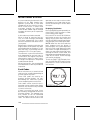
Weighing the Risks vs Benefits
In order to decide whether or not you
should wear a helmet, it is best to consider the particular environment you
will be riding in, as well as other factors such as personal experience. Will
there be a lot of traffic on the water?
What is your riding style?
F00A2GY
TYPE V — WEARABLE
Helmets
Some Important Considerations
Helmets are designed to offer some
degree of protection in case of impacts to the head. In most motorized
sports, the benefits of wearing a helmet clearly outweigh the drawbacks.
However, in the case of motorized watersports such as riding personal watercraft, this is not necessarily true as
there are some particular risks associated with the water.
Benefits
A helmet helps to reduce the risk of
injury in case of a head impact against
a hard surface such as another craft in
the case of a collision. Similarly, a helmet with a chin guard might help prevent injuries to the face, jaw or teeth.
Risks
On the other hand, in some situations
when falling off the watercraft, helmets have a tendency to catch the
water, like a “bucket”, and put severe
stresses on the neck or spine. This
could result in choking, severe or permanent neck or spine injury or death.
Helmets may also interfere with peripheral vision and hearing, or increase
fatigue which, could contribute to increase the risk of a collision.
22
_______
The Bottom Line
Since each option minimizes some
risks, but increases others, before
each ride you must decide whether
to wear or not wear a helmet based on
your particular situation.
If you decide to wear a helmet, you
must then decide what type is the
most appropriate for the circumstances. Look for helmets that meet
DOT or Snell standards, and if possible, choose one designed for motorized watersports.
Additional Recommended
Equipment
It is recommended that you acquire
additional equipment for safe, enjoyable cruising. This list, which is not all
inclusive, includes items you should
consider acquiring.
– Small tool kit
– Local map
– First aid kit
– Tow rope
– Flares
– Paddle
– Anchor
– Mooring cords.
A cellular telephone in a waterproof
bag or container has also been found
to be beneficial to boaters when in distress or just for contacting someone
on shore.
SAFETY INFORMATION
________
NAVIGATION RULES
Operating Rules
Operating a watercraft can be compared with driving on unmarked highways and roads. To prevent collisions
or avoid other boaters, a system of operating rules must be followed. It’s not
only common sense... it’s the law!
Generally keep to your right and safely
avoid collisions by keeping a safe distance from other watercrafts, boats,
people and objects.
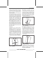
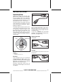
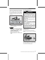
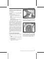
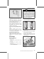
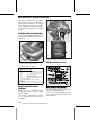
The following illustration identifies different parts of the boat that are used
as directional reference points, the
bow being the front of the boat. The
port side of boat (left side) is visually
identifiable by a RED light off the bow,
and the starboard side (right side) by a
GREEN light.
Bow
Starboard
Port
F00A14Y
TYPICAL
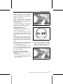
Like a street traffic light, if you see a
RED light, STOP, give the right of way.
The other boat is to your right and it has
the right of way.
If you see a GREEN light, pass with
caution. The other boat is to your left,
you have the right of way.
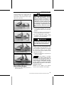
Meeting Head-On
Keep right.
2
1
F00A15Y
TYPICAL
F00A13Y
Stern
TYPICAL - DIRECTIONAL REFERENCE
POINTS
1. RED light
2. GREEN light (yield zone)
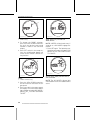
Crossing
Give the right of way to a watercraft
ahead and to your right. Never cross
in front of a boat, you should see his
RED light, he should see your GREEN
light (he has the right of way).
Personal watercrafts (PWC) do not
have these colored lights, but the rule
still applies.
________
Passing
Give the right of way to other crafts and
keep clear.
F00A16A
TYPICAL
SAFETY INFORMATION
________
23
NAVIGATION RULES
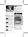
Navigation System
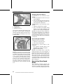
Navigational aids, such as signs or
buoys, can assist you in identifying safe waters. Buoys will indicate
whether you should keep to the right
(starboard) or to the left (port) of the
buoy, or to which channel you can continue. They may also indicate whether
you are entering a restricted or controlled area such as a no wake or low
speed zone. They may also indicate
hazards or pertinent boating information. Markers may be located on shore
or on the water. They can also indicate speed limits, no power craft or
boating, anchorage and other useful
information. (The shape of each type
of marker will provide assistance).
Make sure you know and understand
the navigation system applicable to
the waterways where you intend to
use the watercraft.
Collision Avoidance
– Do not release throttle to steer.
WARNING
Do not release the throttle when
trying to steer away from objects
without the use of the braking system. Engine power and jet pump
thrust is required to steer the watercraft.
– Always keep a constant lookout for
other water users, other boats or
objects, especially when turning.
Be alert for conditions that may limit
your visibility or block your vision of
others.
– Respect the rights of other recreationists and/or bystanders and always keep a safe distance from all
other watercrafts, boats, people
and objects.
– Do not jump wakes or wakes.
24
_______
WARNING
Do not wake or wave jump, ride
the surf line or attempt to spray or
splash others with your watercraft.
You may misjudge the ability of the
watercraft or your own riding skills
and strike a boat or person.
– This watercraft has the capability of turning more sharply than
other boats, however, unless in an
emergency, do not negotiate sharp,
high speed turns. Such maneuvers
make it hard for others to avoid you
or understand where you are going.
Also, you and/or your passenger(s)
could be thrown from the watercraft.
– Unlike most other watercrafts, this
PWC has a braking system. Practice stopping and docking in a safe,
traffic free area to become familiar
with the watercrafts stopping distance under varying conditions.
– When operating an iBR equipped
watercraft, be aware that other
boats following or operating in close
proximity may not be able to stop as
quickly.
– When at speed and the brake is first
applied, a plume of water will shoot
up in the air behind the watercraft
and may cause the operator of the
following watercraft loose sign of
your PWC.
– It is important to inform the operator of a watercraft who intends to
follow in a convoy formation of the
braking and maneuvering capability of your PWC, what the plume of
water indicates, and that a greater
distance should be maintained between both of you.
SAFETY INFORMATION
________
NAVIGATION RULES
WARNING
Stopping distance will vary depending on initial speed, load,
wind and water conditions.
– Maintaining or increasing speed
may be necessary to avoid a collision.
________
SAFETY INFORMATION
________
25
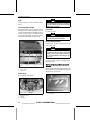
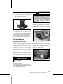
FUELING
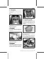
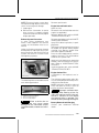
Fueling Procedure
WARNING
WARNING
Fuel is flammable and explosive
under certain conditions. Always
work in a well ventilated area. Do
not smoke or allow open flames or
sparks in the vicinity.
Turn off engine.
WARNING
Always stop the engine before refueling.
Do not allow anyone to remain on the
watercraft.
Tie watercraft securely to the fueling
pier.
Have a fire extinguisher close at hand.
To prevent fuel back-flow, fill up
tank slowly so the air can escape
from the fuel tank.
Stop filling immediately after the release of the gas pump nozzle handle
and wait a moment before removing
the spout. Do not retract the gas pump
nozzle to put more fuel in fuel tank.
WARNING
Do not overfill or top off the fuel
tank and leave the watercraft in the
sun. As temperature increases,
fuel expands and may overflow.
Close the fuel tank cap and ensure it is
properly latched.
WARNING
Always wipe off any fuel spillage
from the watercraft.
After refueling always, open seat, remove the ventilation box, and ensure
there is no gasoline vapor odor inside
the engine compartment.
WARNING
Do not start watercraft if gasoline
or gasoline vapor odor is present.
sdd2009-001-054_a
TYPICAL - FUEL TANK CAP LOCATION
Lightly press down on the cap with
your LH hand as you pull up on the latch
with your fingers to release it. The cap
will pop open as it is pushed open by
spring pressure.
WARNING
Fuel tank may be pressurized,
place one hand over the fuel cap
when releasing the cap retaining
latch.
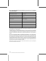
Recommended Fuel
Use unleaded gasoline with the following octane rating.
NOTICE Never experiment with
other fuels or fuel ratios. Never
use fuel containing more than 10%
ethanol or methanol. The use of a
non-recommended fuel can result in
decreased engine performance and
damage to critical parts in the fuel
system and engine.
Insert the gas pump spout into the filler
neck and fill up fuel tank.
26
_______
SAFETY INFORMATION
________
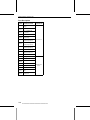
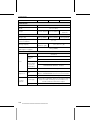
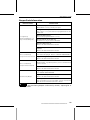
FUELING
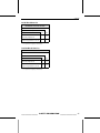
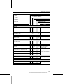
Inside North America
MINIMUM OCTANE RATING
87 (RON + MON)/2
91 (RON + MON)/2
ENGINES
155 HP
Naturally-aspirated
215 and 260HP
Supercharged Intercooled
(1)
91
87
--
X
X(1)
X
For optimum engine performance.
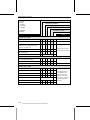
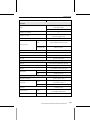
Outside North America
MINIMUM OCTANE RATING
92 RON
95 RON
ENGINES
155 HP
Naturally-Aspirated
215 and 260 HP
Supercharged Intercooled
(1)
95
92
--
X
X(1)
X
For optimum engine performance.
________
SAFETY INFORMATION
________
27
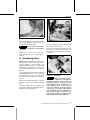
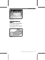
TRAILERING INFORMATION
NOTICE The span of the trailer
wood bunks including bunk width
should be adjusted to provide support throughout the full length of the
hull. The ends of both trailer wood
bunks should not exceed the length
of the watercraft.
NOTICE Do not route ropes or
tie-downs over the seat or grab
handle as they could be permanently damaged. Wrap ropes or
tie-downs with rags or similar protectors where they can come into
contact with the watercraft body.
Ensure the trailer wheels are positioned so that the center of gravity of
the watercraft is slightly ahead of the
wheels to properly support the weight
of the watercraft.
RXT iS, GTX iS and GTX Limited iS
Models
WARNING
Never tip this watercraft on end for
transporting. We recommend that
you carry the watercraft in its normal operating position.
Check the applicable laws and regulations in your area concerning towing
a trailer, especially for the following
items:
– Brake system
– Tow vehicle weight
– Mirrors.
Take the following precautions when
towing the watercraft:
– Respect tow vehicle maximum
weight capacity and the tongue
weight capacity as recommended
by manufacturer.
– Tie the watercraft to both front and
rear (bow/stern) eyelets so that it is
firmly secured on the trailer. Use additional tie-downs if necessary.
– Ensure fuel tank cap, front storage compartment cover, glove box
cover, boarding platform and seat
are properly latched.
– Observe trailering safety precautions.
28
_______
WARNING
Ensure the watercraft moving deck
is down in the DOCK MODE position before trailering. This will
lower the center of gravity and improve trailer stability.
All Models
WARNING
Make sure seat is securely latched
prior to trailering.
A Sea-Doo cover can protect the watercraft, particularly when driving on
dirt roads, to prevent dirt entry through
the air inlet openings.
WARNING
When trailering the watercraft,
NEVER leave any equipment on
the watercraft.
WAKE Pro Model
WARNING
NEVER leave a wakeboard installed on the rack. Otherwise,
wake board fin(s) could cause injury to bystanders or wakeboard
could fly off on the road.
SAFETY INFORMATION
________
TRAILERING INFORMATION
WARNING
Bungee cords are under tension
and could spring back and whip
someone when released. Use caution.
NOTE: When trailering 2 watercrafts,
it may be necessary to remove the inner wakeboard rack.
________
SAFETY INFORMATION
________
29
IMPORTANT ON-PRODUCT LABELS
The labels illustrated on the following pages are on your watercraft. If missing or
damaged, they can be replaced free of charge. See an authorized Sea-Doo dealer.
Please read the following labels carefully before operating this watercraft.
NOTE: The first illustration of the watercraft indicates the approximate locations
of the various labels. A dotted line indicates that the label is not on the outer surface, and that the seat or a cover of some type must be opened to see the label.
1
14
3,4,5,7,9
18,19
6
8
10,11,12,13
2
smo2009-002-100_c
TYPICAL - RXT IS, GTX IS, AND GTX LIMITED IS MODELS
smo2010-002-001_a
TYPICAL - GTX 155 AND RXT 215 MODELS
30
_______
SAFETY INFORMATION
________
IMPORTANT ON-PRODUCT LABELS
smo2010-002-002_a
WAKE PRO MODEL
smo2010-002-003_a
RXT-X MODEL
219903201
LABEL 1: TYPICAL
________
SAFETY INFORMATION
________
31
IMPORTANT ON-PRODUCT LABELS
smo2009-002-106_aen
LABEL 6: TYPICAL
smo2009-002-103_a
LABEL 2: TYPICAL
219903177
LABEL 7: TYPICAL
219903184
LABEL 3: FIXED DECK MODELS
smo2009-002-107_aen
LABEL 8: TYPICAL
219903084
LABEL 3: iS MODELS
F00A2TY
LABEL 9: TYPICAL
smo2009-002-105_aen
LABEL 4: TYPICAL
F18L0NY
LABEL 5: TYPICAL
32
_______
smo2009-002-108_aen
LABEL 10: TYPICAL
SAFETY INFORMATION
________
IMPORTANT ON-PRODUCT LABELS
smo2009-002-109_a
LABEL 11: TYPICAL
219903137
LABEL 15: TYPICAL
smo2009-002-110_aen
LABEL 12: TYPICAL
219903228
LABEL 16: TYPICAL
smo2009-002-111_a
LABEL 13: TYPICAL
smo2009-002-112_a
LABEL 14: TYPICAL (WATERCRAFT
OUTSIDE NORTH AMERICA)
________
SAFETY INFORMATION
________
33
IMPORTANT ON-PRODUCT LABELS
219903197
LABEL 18: TYPICAL
219903198
LABEL 19: TYPICAL
34
_______
SAFETY INFORMATION
________
PRE-RIDE INSPECTION
WARNING
Perform a pre-ride inspection before each ride to detect potential problems
during operation. The pre-ride inspection can help you monitor wear and
deterioration before they become a problem. Correct any problems that
you discover to reduce the risk of a breakdown or crash. See an authorized
Sea-Doo dealer as necessary.
Before performing the pre-ride inspection, read and understand the CONTROLS
section.
What to Do Before Launching the Watercraft
WARNING
Engine should be off and the D.E.S.S. key should always be removed from
its post prior to verifying any of the following points. Only start watercraft
once all items have been checked and operate properly.
Check the items listed in the following table before launching the watercraft.
ITEM
OPERATION
Hull
Inspect.
Jet pump water intake
Inspect/clean.
Drain plugs
Tighten.
Fuel tank
Refill.
Engine compartment
Check for any fluid leaks and gasoline vapor odor.
Engine oil level
Check/refill.
Engine coolant level
Check/refill.
Steering system
Check operation.
Throttle lever
Check operation.
iBR lever
Check operation.
Intelligent Suspension (iS)
Check operation.
Front storage compartment cover,
boarding platform and seat
Ensure they are closed and latched.
Self-contained removable storage bin
Ensure it is installed on watercraft and properly closed
and latched.
Wakeboard rack
– Ensure rack is properly installed and secured.
– Make sure bungee cords are in good condition.
– Ensure wakeboard is correctly installed in rack and
secured.
Ski/wakeboard post
Inspect and check operation.
✓
D.E.S.S. post and engine start/stop button Check operation.
________
SAFETY INFORMATION
________
35
PRE-RIDE INSPECTION
Hull
Inspect hull for cracks and other damages.
Jet Pump Water Intake
Remove weeds, shells, debris or anything else that could restrict the flow of
water and damage the propulsion unit.
Clean as necessary. If any obstruction
cannot be removed, refer to an authorized Sea-Doo dealer for servicing
WARNING
Ensure bilge drain plugs are properly secured prior to launching the
watercraft in water.
Fuel Tank
Fill the fuel tank.
WARNING
Strictly adhere to instructions in
the FUELING PROCEDURE.
Engine Compartment
Inspect the engine compartment for
fuel vapor odor.
WARNING
Should any leak or gasoline odor
be present, do not apply electrical
power or start the engine. Refer to
an authorized Sea-Doo dealer before use.
To access the engine compartment,
open the seat.
1
F18J04Y
RXT iS, GTX iS and GTX Limited iS
Models
2
TYPICAL — INSPECT THESE AREAS
1. Water intake
2. Ride plate
Also remove the ventilation box by depressing the 3 locking tabs and lifting it
off the deck extension.
Drain Plugs
Secure bilge drain plugs.
smo2009-002-002_b
smo2009-002-135_a
TYPICAL
1. Bilge drain plugs
2. Tighten
3. Untighten
36
_______
1. Ventilation box
2. Locking tabs
SAFETY INFORMATION
________
PRE-RIDE INSPECTION
WARNING
Check handlebar and corresponding steering nozzle operation before starting. Never turn handlebar while someone is near the rear
of the watercraft. Keep away from
steering moving parts (nozzle, iBR
gate, linkages etc.).
smo2009-002-003
VENTILATION BOX REMOVED
Engine Oil
Ensure oil level is within specification
as described in MAINTENANCE PROCEDURES section.
Engine Coolant
Ensure coolant level is within specification as described in MAINTENANCE
PROCEDURES section.
Fixed Deck Models
Check for coolant leaks on engine, in
bilge and from ride plate.
WARNING
When operating the engine with
the watercraft out of the water, the
engine and heat exchanger in the
ride plate may become very hot.
Avoid any contact with hot engine
parts and the ride plate as burns
may occur.
Throttle Lever
Check the Electronic Throttle Control
lever (ETC) for free and smooth operation. It should return to its initial position immediately after it is released.
WARNING
Check throttle lever operation before starting the engine. If any friction is felt in the throttle lever, refer
to an authorized Sea-Doo dealer.
iBR Lever
(intelligent Brake and Reverse)
Check the iBR lever for free and
smooth operation. It should return
to its initial position immediately after
it is released.
WARNING
Check iBR lever operation before
starting the engine. If any friction
is felt in the iBR lever, refer to an
authorized Sea-Doo dealer.
iS Suspension
Steering System
Assisted by another person, check
steering operation for free movement.
When the handlebar is horizontal,
the jet pump nozzle should be in the
straight ahead position. Ensure the jet
pump nozzle pivots easily and in the
same direction as the handlebar (e.g.:
when handlebar is turned to the left,
the nozzle opening must point towards
the LH side of watercraft).
________
RXT iS, GTX iS, GTX Limited iS
Models
1. Press briefly the start/stop button to
wake-up the ECM.
2. Press on iS UP/DOWN arrow button
to confirm suspension operation.
SAFETY INFORMATION
________
37
PRE-RIDE INSPECTION
Storage Compartments, Boarding
Platform and Seat
Ensure all required safety and survival
equipment and any additional cargo is
properly stored in the storage bins provided.
Ensure the self-contained storage bin
cover, front cover, glove box, boarding
platform, access panels, and seat are
closed and latched.
WARNING
Ensure the seat, boarding platform, access panels, and all storage compartment covers are securely latched.
RXT iS, GTX iS and GTX Limited iS
Models
Ensure there are no items of cargo, or
other material, between the moving
deck and fixed deck.
WARNING
Do not store cargo or material of
any type in the space between the
moving and fixed deck, or near
the rear suspension control arm.
These areas must remain free of all
obstructions to permit free movement of the deck and any water
which may accumulate in the foot
well areas. Use only provide storage compartments.
Wakeboard Rack
WAKE Pro Model
WARNING
Ensure wakeboard rack is properly
secured to watercraft body, and
that the wakeboard is properly positioned and secured to the rack
prior to using watercraft. Ensure
wakeboard retaining straps are in
good condition.
38
_______
Ski/Wakeboard Post
WAKE Pro Model
Make sure ski/wakeboard post is fully
extended and locked before use.
Completely retract and lock when not
used.
WARNING
Use caution with skier/wakeboarder in tow as tow rope may
backlash to watercraft when released. Never perform a sharp
turn when towing a skier, wakeboarder or any toy.
NOTICE The ski/wakeboard post is
designed for towing a skier or wakeboarder with a maximum gross
weight of 114 kg (250 lb).
D.E.S.S. Post and Engine Start/Stop
Button
Press the start button once without
installing the lanyard on the D.E.S.S.
post. The information center will come
ON, proceed through its self test function, and shut down all indications after
a few seconds.
Install the D.E.S.S. key (lanyard) on the
D.E.S.S. post (emergency engine stop
switch). The information center will
come back ON, cycle through it's self
test and stay on for approximately 3
minutes.
Press the start/stop button to start the
engine, then stop it by pressing the
start/stop button a second time.
Restart the engine, then stop it by removing the lanyard from the D.E.S.S.
post.
SAFETY INFORMATION
________
PRE-RIDE INSPECTION
WARNING
Should the D.E.S.S. key be loose or
fail to remain on its post, replace it
immediately in order to avoid unsafe use. If removing the lanyard
or pressing the start/stop button
does not stop the engine, do not
use the watercraft. See your authorized Sea-Doo dealer for system testing and repairs.
Check the items listed in the following table after launching the watercraft
and before going for a ride.
OPERATION
Information Center
Intelligent Brake and
Reverse System
(iBR)
Variable Trim System
(VTS)
WARNING
Always ensure proper iBR system
operation before taking the watercraft out for a ride.
What to Do After
Launching the Watercraft
ITEM
2. Start the engine and ensure the watercraft does not move.
3. On the left handlebar, depress the
iBR lever completely in, the watercraft should move slowly backwards.
4. Release the iBR lever, there should
not be any reverse thrust.
✓
Check
operation.
Check
operation.
Check
operation.
Information Center (Gauge)
1. Press start/stop button and install
D.E.S.S. key.
2. As information center cycles
through its self-test function, ensure all indications and indicator
lights come on.
WARNING
Attach the safety lanyard to your
PFD.
iBR System
NOTICE Ensure there is sufficient
space ahead and behind watercraft
to safely carry out the iBR system
test to avoid a collision. Watercraft
will move during test.
Variable Trim System (VTS)
All Except RXT 215 and GTX 155
Models
With the engine running in forward
thrust, push the VTS up/down arrow
button alternately to check VTS operation. Confirm the VTS position indicator movement in the information
center.
Test also the VTS preset trim positions
by double clicking the VTS UP/DOWN
button.
RXT 215 and GTX 155 Models
1. With the engine running in forward
thrust, press the MODE button repeatedly until VTS is visible in the
multifunction display.
2. On the RH handlebar, press the UP
or DOWN arrow button alternately
to change the VTS setting.
3. Confirm VTS operation by looking
for the VTS position indicator movement in the digital display.
4. Press the SET button to save the desired setting and return to the main
display.
1. Remove the moorings securing the
watercraft to the dock.
________
SAFETY INFORMATION
________
39
PRE-RIDE INSPECTION
All Models
NOTE: The VTS system cannot be
tested without the engine operating
in forward thrust. If the engine is not
running in forward thrust, only the VTS
indication will change when the VTS
control switches are pressed; the nozzle will not change position.
40
_______
SAFETY INFORMATION
________
WATERCRAFT
INFORMATION
_______________
41
CONTROLS
3
8 9
6 7
5
4
2
1
10
smo2009-002-200_d
TYPICAL - IDENTIFICATION OF CONTROLS
1. Handlebar
2. Throttle lever
3. iBR lever (intelligent Brake and Reverse)
4. D.E.S.S. post
5. Engine start/stop button
6. VTS button (Variable Trim System)
7. iS button (intelligent Suspension)
8. MODE/SET button
9. UP/DOWN arrow button
10. Cruise button
NOTE: Some indications, functions
and features described in this section
may not apply to every PWC model, or
may be available as an option.
1) Handlebar
The handlebar controls the direction of
the watercraft. During forward operation, turning the handlebar to the right
steers the watercraft to the right and
inversely.
42
However, when operating in reverse,
steering direction is reversed. Turning
the handlebar to the right while backing up steers the watercraft to the left.
WARNING
Check handlebar and corresponding steering nozzle operation before starting. Never turn handlebar while someone is near the rear
of the watercraft. Keep away from
steering moving parts (nozzle, iBR
gate, linkages etc.).
Tilt Adjustment
All Models
The handlebar position can be adjusted
to suit rider preferences.
The entire, handlebars, and steering
column tilts up or down as a unit.
______________
CONTROLS
To perform this adjustment, pull on the
release handle at the base of the steering column just ahead of the glove box,
and tilt the handlebars to the desired
position.
smo2009-002-116_a
STEERING COLUMN ADJUSTMENT LATCH
NOT SECURED
1. Latch pawl engaged in steering column
groove
2. Release handle unlocked
sdd2009-001-088_a
TYPICAL
1. Release handle
2. Available tilt adjustment
3. Multifunction gauge
When the handlebars are at the desired position, release the latch handle
and ensure the latch pawl properly engages a groove in the steering column.
Also ensure the latch handle is in the
forward position.
WARNING
smo2009-002-117_a
To prevent sudden movement of
the steering column, always ensure the pawl on the steering column latch is properly engaged in
one of the grooves on the steering
column.
STEERING COLUMN ADJUSTMENT LATCH
PROPERLY SECURED
1. Latch pawl engaged
2. Release handle locked forward
Ergonomic Adjustments
RXT-X Model
The handlebar width and angular position of the controls may be adjusted to
driver preference by extending and rotating the handlebar extension tubes.
NOTE: To carry out the ergonomic adjustments, see an authorized Sea-Doo
dealer.
_______________
43
CONTROLS
smo2009-002-201_a
smo2010-002-006_c
ERGONOMIC ADJUSTMENTS
1. Handlebar width adjustment
2. Angular position adjustment of controls
2) Throttle Lever
This watercraft is equipped with an intelligent Throttle Control system (iTC)
that uses an electronic throttle control
lever (ETC).
This provides for a more comfortable
throttle operation under demanding
conditions, more precise control,
touring or sport mode of operation,
and allows for interaction with other
electronic control systems such as
O.T.A.S. (Off Throttle Assisted Steering) and iBR (intelligent Brake and Reverse). It also allows for speed limiting
when using cruise mode, slow speed
mode or ski mode.
When the throttle lever is pulled, the
watercraft accelerates. When fully released, the engine automatically slows
down to idle speed and the watercraft will continue forward travel at idle
speed unless the iBR lever is pulled in
for braking or reverse operation, then
released to engage neutral.
1. Throttle lever
2. To accelerate
3. To decelerate
Touring/Sport Mode
The iTC system allows for two modes
of throttle control, TOURING MODE
for progressive throttle response, and
SPORT MODE for instant throttle response. Refer to ACTIVE TECHNOLOGIES.
A TOURING mode indicator or a
SPORT mode indicator is on in the multifunction gauge to confirm the active
mode of operation. By default, the watercraft is set to TOURING mode of
operation when first started.
1
smo2010-002-100_a
1. Touring mode indicator
44
______________
CONTROLS
1
smo2010-002-201_a
1. Sport mode indicator
smo2010-002-102
There are two methods of activating
or deactivating sport/touring modes.
One method requires navigating the
functions available through the information center and should only be used
when the watercraft is stopped. The
other method is used to rapidly switch
between modes while riding at speed.
NOTE: If using a LEARNING or
RENTAL key, sport mode of operation
is not available.
Activating Sport Mode
(Quick Method)
To quickly activate sport mode while
riding at speed, carry out the following:
MESSAGE - ENTERING SPORT MODE INCREASED ACCELERATION INSTRUCT PASSENGERS TO HOLD PRESS_SET_BUTTON
WARNING
Ensure passengers are advised
that sport mode provides for increased accelerations and that
they are to hold on tightly.
2. Press the SET button again to activate sport mode.
A scrolling SPORT MODE ACTIVATED
message will momentarily confirm
that sport mode has been activated.
WARNING
When activating sport mode, be
sure to maintain situational awareness of other watercrafts, obstacles, or persons in the water.
1. Depress and hold the SET button for
at least 3 seconds.
NOTE: The following important message will scroll across the multifunction display: ENTERING SPORT
MODE - INCREASED ACCELERATION - INSTRUCT PASSENGERS TO
HOLD - PRESS_SET_BUTTON.
smo2010-002-103
MESSAGE - SPORT MODE ACTIVATED
NOTE: After a few seconds, the gauge
will revert to its normal display.
3. Ensure the SPORT mode indicator is
turned on.
_______________
45
CONTROLS
2. Ensure the TOURING mode indicator is on.
1
smo2010-002-201_a
1
1. SPORT mode indicator
NOTE: The SPORT mode indicator will
come on and stay on as long as sport
mode is active.
Deactivating Sport Mode
(Quick Method)
To quickly deactivate sport mode while
riding at speed, carry out the following:
smo2010-002-100_a
1. Touring mode indicator
Activating Sport Mode
(Through Information Center)
To activate sport mode through the
gauge functions, carry out the following:
WARNING
When activating sport mode, be
sure to maintain situational awareness of other watercrafts, obstacles, or persons in the water.
1. Depress and hold the SET button for
at least 3 seconds.
NOTE: The following message will
scroll in the multifunction display:
SPORT MODE DEACTIVATED.
WARNING
Activating sport mode through the
information center should only
be carried out with the watercraft
stopped and the engine running
at idle. The operator must ensure
to maintain situational awareness
of other watercrafts, obstacles, or
persons in the water.
1. With the engine running at idle,
press the MODE button repeatedly
until DRIVING MODE scrolls across
the multifunction display.
smo2010-002-105
MESSAGE - SPORT MODE DEACTIVATED
NOTE: After a few seconds, the gauge
will revert to its normal display.
smo2010-002-101
FUNCTION SELECTED - DRIVING MODE
46
______________
CONTROLS
2. Press the SET button to enter the
driving mode function.
NOTE: The following important message will scroll across the multifunction display ENTERING SPORT MODE
- INCREASED ACCELERATION - INSTRUCT PASSENGERS TO HOLD PRESS_SET_BUTTON.
smo2010-002-103
MESSAGE - SPORT MODE ACTIVATED
NOTE: After a few seconds, the gauge
will exit the function and return to its
normal display.
4. Ensure the SPORT mode indicator is
turned on.
smo2010-002-102
MESSAGE - ENTERING SPORT MODE INCREASED ACCELERATION INSTRUCT PASSENGERS TO HOLD PRESS_SET_BUTTON
WARNING
Ensure passengers are advised
that sport mode provides for increased accelerations and that
they are to hold on tightly.
3. Press the SET button again to activate sport mode.
A scrolling SPORT MODE ACTIVATED
message will confirm momentarily
that sport mode has been activated.
1
smo2010-002-201_a
1. SPORT mode indicator
NOTE: The SPORT mode indicator
will come on and stay on as long as
sport mode is active. If the engine is
not at idle and sport mode cannot be
activated, the following message will
appear: SPORT MODE - RETURN TO
IDLE TO ACTIVATE.
Deactivating Sport Mode
To deactivate sport mode, carry out the
following:
_______________
47
CONTROLS
WARNING
Deactivating sport mode through
the information center must only
be carried out with the watercraft
stopped and the engine running at
idle.
NOTE: The following message will
scroll in the multifunction display
SPORT MODE DEACTIVATED.
1. With the engine running at idle,
press the MODE button repeatedly
until DRIVING MODE scrolls across
the multifunction display.
smo2010-002-105
MESSAGE - SPORT MODE DEACTIVATED
NOTE: After a few seconds, the gauge
will exit the function and return to its
normal display.
4. Ensure the TOURING mode indicator is on.
smo2010-002-101
FUNCTION SELECTED - DRIVING MODE
2. Press the SET button to enter driving mode function.
NOTE: The
following
message
will scroll in the multifunction
display SPORT MODE ACTIVE PRESS_SET_TO_DISENGAGE.
1
smo2010-002-100_a
1. Touring mode indicator
3) iBR Lever (intelligent
Brake and Reverse)
smo2010-002-104
MESSAGE - SPORT MODE ACTIVE PRESS_SET_TO_DISENGAGE
3. Press the SET button again to disengage sport mode.
48
The iBR lever on the LH handlebar can
electronically command either reverse
or braking modes.
To activate either reverse or braking
modes, release the throttle lever and
pull in the iBR lever.
NOTE: Less than 25% of lever travel
will not activate reverse or braking
modes.
______________
CONTROLS
safety lanyard be securely snapped
onto it for the watercraft to be fully operational.
smo2009-002-202_a
iBR LEVER
1. iBR lever
2. Lever released position
3. Approximate 25% position
4. Operating range
sdd2009-001-019_a
If the engine is not running, the iBR
lever will not have any effect on the
iBR gate position. The engine must be
running for the iBR gate to move when
the iBR lever is pulled in.
When the iBR lever is released after
braking or reverse operation, the iBR
gate will move to the neutral position.
If throttle lever is still pulled in when
releasing the iBR lever, forward movement will be initiated after a short delay. This function is useful when it is
necessary to accelerate rapidly after
a braking maneuver, or stop rearward
velocity after reverse operation.
TYPICAL
1. D.E.S.S. post
2. Start/stop button
Always attach the safety lanyard to
the operators Personal Flotation Device (PFD) and snap the key onto the
D.E.S.S. post to enable engine starting.
Two short beeps indicate the system
is ready to allow engine starting. Otherwise, refer to the TROUBLESHOOTING section.
WARNING
If throttle lever is still pulled in
when releasing the iBR lever, forward movement will be initiated
after a short delay. If forward acceleration is not desired, release
the throttle lever.
To engage forward from neutral, tap
on the throttle lever. The iBR gate will
move to the forward thrust position.
4) D.E.S.S. Post
(Emergency Engine
Stop Switch)
The D.E.S.S. post (Digitally Encoded
Security System) requires that a programmed D.E.S.S. key attached to a
smo2009-002-115_a
TYPICAL
1. Key on the D.E.S.S. post
2. Safety lanyard secured to operators' PFD
Should an emergency arise during engine operation, pulling the key from the
D.E.S.S. post stops the engine operation.
If the engine is shut off using the
start/stop button and the D.E.S.S. key
is left on its post, the information cen-
_______________
49
CONTROLS
ter and all electrical power will shut off
after approximately three minutes to
prevent battery discharge.
WARNING
While the engine can be stopped
using the engine start/stop button,
good habits recommend that the
D.E.S.S. key also be disconnected
when stopping the engine and disembarking.
Each key has a safety lanyard with float
attached to it. This prevents the key
from sinking should it be dropped in
the water.
To ease key recognition, the key float
comes in different colors.
KEY TYPE
FLOAT COLOR
Normal
Yellow or Black
Learning
Green
Rental
Orange
WARNING
Should the engine be stopped, the
brake function and all watercraft
directional control is lost. Always
disconnect D.E.S.S. key when watercraft is not in operation in order
to prevent accidental engine starting or to avoid unauthorized use
by others, children, and to prevent
theft.
Digitally Encoded Security System
(D.E.S.S.)
Each D.E.S.S. key contains an electronic circuit that is programmed to
give it a unique electronic serial number. This is the equivalent of a conventional key.
The D.E.S.S. system reads the key installed on the post and only allows engine starting for keys it recognizes.
The D.E.S.S. system brings great
flexibility. You can buy an additional
D.E.S.S. key and have it programmed
for your watercraft.
A total of ten D.E.S.S. keys can be programmed.
sdd2009-001-025
TYPICAL - D.E.S.S. KEYS (LANYARDS)
1. Learning key, green float
2. Rental key, orange float
When the start/stop button is pressed
and a key is installed on the D.E.S.S.
post, the information center will execute its self test function, display a
scrolling welcome message, and then
display a message of key recognition
(normal key, learning key or rental key).
The Normal D.E.S.S. key allows full use
of available engine power.
D.E.S.S. Key Types
Three types of keys can be used:
– Normal key
– Learning key
– Rental key (sold separately).
50
______________
CONTROLS
To change learning or rental key settings, carry out the following:
1. Press the start/stop button to wake
up the electrical system and install
the NORMAL key on the D.E.S.S.
post.
2. Wait for the information center to
complete its self-test and display
the key recognition message.
3. Press the MODE button repeatedly
until KEY MODE is visible in the digital screen of the information center.
smo2009-002-114_a
NORMAL KEY RECOGNIZED
The SEA-DOO learning key or the
rental key, limits the speed of the watercraft and the engine torque, therefore enabling first time users and less
experienced operators to learn how to
operate the watercraft while gaining
the necessary confidence and control.
sdd2009-001-024_b
TYPICAL - GAUGE CONTROL BUTTONS
1. MODE button
2. SET button
3. UPDOWN arrow button
smo2009-002-114_aa
LEARNING KEY RECOGNIZED
NOTE: Any key may be programmed
to more than one watercraft. In fact,
the watercraft is programmed to recognize the key.
Changing Learning or Rental Key
Speed Settings
Both the rental and learning keys each
offer five speed limitation settings with
the slowest at setting 1 increasing
to setting number 5. By default, the
learning key and rental key are preset
to the highest speed setting (5).
NOTE: Changing key settings is only
available when the engine is not running.
smo2009-002-114_b
FUNCTION SELECTED - KEY MODE
4. Press the SET button once to enable
learning key mode setting function.
The display will change to L-Key.
_______________
51
CONTROLS
D.E.S.S.
KEY TYPE
smo2009-002-114_c
KEY
SPEED
SETTING
APPROX.
MAX.
SPEED
5
58 km/h
(36 MPH)
4
55 km/h
(34 MPH)
3
50 km/h
(31 MPH)
2
47 km/h
(29 MPH)
1
42 km/h
(26 MPH)
5
74 km/h
(46 MPH)
4
69 km/h
(43 MPH)
3
63 km/h
(39 MPH)
2
58 km/h
(36 MPH)
1
51 km/h
(32 MPH)
Learning
key
EXAMPLE - LEARNING KEY SET TO 1
NOTE: Pressing the SET button twice
will enable the Rental key setting function. The display will change to R-Key.
Rental key
smo2009-002-114_cc
EXAMPLE - RENTAL KEY SET TO 5
5. Press the UP or DOWN arrow button to toggle the key setting between 1 and 5. See table for speed
limitations according to setting.
6. Press the SET button once to save
the setting, twice to exit the function, or simply wait for the function
to time-out. The change in key setting will automatically be saved.
NOTE: The key speed setting is applicable to any key of the same type used
on a specific watercraft. The same
key type used on a different watercraft
may therefore have a different key
speed setting.
5) Engine Start/Stop
Button
The engine start/stop button is located
on the LH handlebar. It is used to wake
up the electrical system as well as to
start and stop the engine.
sdd2009-001-019_a
TYPICAL
1. D.E.S.S. post
2. Start/stop button
52
______________
CONTROLS
Waking Up the Electrical System
Press the start/stop button once without installing the D.E.S.S. key on its
post.
This will power up the electrical system; the information center will cycle
through a self-test function, display a
scrolling welcome message followed
by a key recognition message, and will
then go blank after a few seconds.
The electrical system will stay powered up for approximately 3 minutes
after the start/stop button was depressed.
This function allows the suspension to
be activated without starting the engine.
NOTE: If the start/stop button is
pressed and held without the D.E.S.S.
key installed, the information center
displays will stay on as long as the
start/stop button is held.
sdd2009-001-019_c
TYPICAL - VTS CONTROL BUTTON
1. Bow up
2. Bow down
Watercraft trim position can be seen
on the VTS position indicator in the information center digital screen.
NOTE: Changing the VTS trim position
without the engine running in forward
thrust mode only changes the indication. The nozzle will then move to the
selected VTS trim position when forward thrust is engaged.
Engine Starting and Stopping
Refer to OPERATING INSTRUCTIONS
for complete procedure to start and
stop the engine.
6) VTS Button (Variable
Trim System)
This watercraft is equipped with a programmable high performance VTS.
It provides watercraft pitch trim adjustments by adjusting the vertical position
of the jet nozzle.
The VTS can be manually trimmed to
desired attitude, or to one of two preset trim positions.
Press VTS control button (up or down
arrow) to adjust riding attitude of the
watercraft.
sdd2009-001-042_a
INFORMATION CENTER — VTS POSITION
INDICATOR
1. Bow up
2. Bow down
NOTE: Only the segment indicating
the relative position of the VTS will
be on. The illustration shows all segments on as visible during the self test
function.
_______________
53
CONTROLS
Manually Trimming the VTS
All Except RXT 215 and GTX 155
Models
1. To manually trim the VTS, click
(press) the VTS UP or DOWN arrow button once to trim the VTS one
increment (up or down as selected).
2. After a short delay, click it again to
move the VTS one more increment.
Repeat previous step until desired
trim attitude is achieved.
NOTE: A total of nine trim positions
are available.
NOTE: The VTS UP or Down button
can also be pressed and held until the
desired attitude is obtained. The jet
pump nozzle will keep moving until
the trim button is released, or the maximum trim position (up or down) is
reached.
RXT 215 and GTX 155 Models
These models are not equipped with
a VTS trim button. Refer to VTS POSITION in INFORMATION CENTER for
instructions.
Using Preset Trim Positions
Two preset trim positions can be selected.
To select the highest trim position
recorded, double-click on the VTS UP
arrow button (bow up).
To select the lowest trim position
recorded, double-click on the VTS
DOWN arrow button (bow down).
NOTE: If only one preset trim position
is recorded, double-click either UP or
DOWN arrow of the VTS button.
54
sdd2009-001-019_c
DOUBLE-CLICK UP OR DOWN TO USE
PRESET POSITIONS
1. Highest preset position on UP arrow
2. Lowest preset position on DOWN arrow
Recording Preset Trim Positions
You can preset VTS positions for quick
settings when adjusting watercraft
trim.
Two different trim positions can be
recorded, one for each UP or DOWN
arrow of the VTS button. As an example, one can be preset for operating
the watercraft with operator only, the
other for operator and a passenger.
The VTS system will compare trim settings recorded, the highest position
will be assigned to the UP arrow (bow
up), the lowest to the DOWN arrow
(bow down).
If both trim positions are identical, both
buttons will have the same trim settings.
During preset adjustment, any of the
9 indicated VTS positions can be selected for each preset position. The
factory default settings are PRESET 1
is set to 4, and PRESET 2 is set to 5.
To record VTS preset trim positions:
1. Turn on the electrical power by
pressing the start/stop button once
without installing the D.E.S.S. key
on its post.
2. On the RH handlebar, press the
MODE button repeatedly until VTS
MODE is displayed.
______________
CONTROLS
2
1
sdd2009-001-024_b
3
1. MODE button
2. SET button
3. UP/DOWN arrow button
smo2009-002-114_e
FUNCTION SELECTED - PRESET 1
1. Preset 1 function
2. VTS setting selected to 1
3. VTS position indicator at setting 1 (bow
down)
5. Press the SET button to save PRESET 1 and display PRESET 2.
6. Press the VTS UP or DOWN button
to change the PRESET 2 VTS position. Gauge will display setting 1
through 9 in the digital screen above
PRESET 2.
smo2009-002-114_d
FUNCTION SELECTED - VTS MODE
3. On the RH handlebar, press the SET
button to display PRESET 1.
4. Press the VTS UP or DOWN button
to change the PRESET 1 VTS position. Gauge will display setting 1
through 9 in the digital screen above
PRESET 1.
2
1
3
smo2009-002-114_f
FUNCTION SELECTED - PRESET 2
1. Preset 2 function
2. VTS setting selected to 9
3. VTS position indicator at setting 9 (bow up)
7. Press the SET button to save the
settings and return to the main display.
_______________
55
CONTROLS
7) iS Button (intelligent
Suspension)
RXT iS, GTX iS and GTX Limited iS
Models
The suspension height (up position) is
factory calibrated to a preset height for
most riding conditions while cruising
in AUTO SUSPENSION MODE. The
factory calibrated height is the same
regardless of the number of passengers or weight on the moving deck.
WARNING
Avoid riding in very rough waters
or practicing extreme maneuvers
like jumping wakes or waves.
Manually Adjusting Ride Height
Press the iS UP or Down arrow button
once to move the suspension to the
next height increment, or press and
hold the button until the desired ride
height is obtained.
WARNING
Do not overload the watercraft
or take on more passengers than
designated. Refer to SPECIFICATIONS for details.
The iS button is primarily used to manually fine-tune the suspension height to
operator preference.
Using the iS button to change the suspension height overrides the AUTO
SUSPENSION MODE function. The
iS system switches to MANUAL SUSPENSION MODE and the operator can
select a different suspension height
as preferred in accordance with riding
style and riding conditions.
Suspension height and mode of operation is indicated in the information center digital screen.
WARNING
Your PWC is equipped with an intelligent suspension. Although
the system absorbs part of the vertical forces and therefore reduces
the impact force to the body, it cannot eliminate it completely. To
prevent you and your passenger
from being bounced and eventually be ejected from the watercraft,
reduce your speed.
56
sdd2009-001-019_d
TYPICAL
1. iS UP arrow button
2. iS Down arrow button
The following indications of manual
suspension mode can be observed in
the digital screen of the information
center:
– A scrolling message in the digital
screen that states MANUAL SUSPENSION.
– The AUTO indication in the iS display will disappear.
– The suspension position indicator
will indicate the relative suspension
height (only one segment of the indicator will be on).
______________
CONTROLS
3
2
8) MODE/SET Button
These buttons located on the RH handlebar.
Press MODE to scroll various functions through the digital screen in the
information center.
Press SET to select the desired function or to save any modified settings.
1
smo2009-002-114_g
1. MANUAL SUSPENSION message
2. AUTO mode indicator OFF
3. Relative suspension position indication
Selecting Auto Suspension Mode
To revert back to AUTO selection
mode, double click the iS UP arrow
button.
The following indications of automatic
suspension mode can be observed in
the digital screen of the information
center:
– A scrolling message in the digital
screen stating AUTOMATIC SUSPENSION.
– The AUTO indication in the iS display will appear.
– All segments of the suspension position indicator will be on.
3
2
sdd2009-001-024_b
1. MODE
2. SET
3. UP/DOWN arrow button
For further details on the information
center and the display modes, refer to
INFORMATION CENTER.
9) UP and DOWN Arrow
Button
These buttons located on the RH handlebar.
Press UP or DOWN arrow button to
navigate through the selected function
using SET or to modify settings.
1
smo2009-002-114_h
1. AUTOMATIC SUSPENSION message
2. AUTO mode indicator on
3. All segments of suspension position
indicator ON
sdd2009-001-024_b
1. MODE
2. SET
3. UP and DOWN arrow button
_______________
57
CONTROLS
NOTE: The UP and DOWN arrow buttons are also used for adjusting watercraft speed when operating in SKI
mode, CRUISE mode or SLOW SPEED
mode.
For further details on the information
center and the display modes, refer to
INFORMATION CENTER.
10) Cruise Button
Except RXT-X Model
The Cruise button is located on the
RH handle bar, just below the UP and
DOWN arrow button. It is used to activate or deactivate CRUISE mode or to
engage SLOW SPEED MODE.
Refer to OPERATING INSTRUCTIONS
for instructions on how to engage and
use CRUISE mode and SLOW SPEED
mode.
58
______________
INFORMATION CENTER (GAUGE)
The information center is a cluster of
gauges, indicator lights and a digital
screen to display operational information to the operator.
The text message can be displayed in
different languages and the units of
measurement can be displayed in metric or imperial units. See an authorized
Sea-Doo to have the information center set to the unit of measurement and
available language of your choice.
It allows the operator to view at a
glance several indications such as
speed, engine RPM, fuel level and engine temperature. The gauge can also
be used to navigate through and select
several functions, modes of operation
and change certain settings and system parameters.
Indicator lamps advise the operator of
selected functions or malfunctions.
The gauge incorporates a GPS (global
positioning system) that it uses for the
altitude, compass, and speedometer
indications, and to provide signals to
other systems as required for their operation.
An information center self test can
be initiated by pressing the start/stop
button (without the D.E.S.S. key installed). All LCD segments and indicator lights will turn on for approximately
3 seconds. The analog speedometer
and RPM indications will also cycle
through their full scale of operation.
This allows the operator to validate
that all indicators are working properly.
Should a fault be detected during the
self-test function, an error message
will be displayed, an indicator light may
come on, and an audible signal (beep
code) may be heard to signal that a
fault has been detected.
A fault code can be generated and
memorized to assist your authorized
Sea-Doo dealer in troubleshooting the
faulty system. Refer to FAULT CODE
DISPLAY in this section for instructions
on how to display fault codes.
WARNING
Watching or using the functions
available through the information
center can distract from the operation of the watercraft, particularly
from constantly scanning the environment. Always ensure your
environment is clear and free from
obstacles or persons in the water,
and bring the watercraft to a low
speed before using any functions
in the information center.
NOTE: Some indications, functions
and features described in this section
may not apply to every PWC model,
or may be available as an option. See
your authorized Sea-Doo dealer for information on available options for your
PWC.
_______________
59
INFORMATION CENTER (GAUGE)
1
9
3
8
7
2
in
lap
AM
RPMgal/h
4
15
6
10
11
13
12
smo2010-002-200_a
INFORMATION CENTER FUNCTIONS
1. Speedometer
2. Tachometer
3. Digital screen
4. Indicator lights
5. Fuel level
6. VTS position
7. iS position
8. Numerical display
9. Multifunction display
10. Depth sounder indicator
11. Water temperature display
12. Hour meter display
13. iBR position
14. Compass
15. Touring mode indicator
16. Sport mode indicator
60
______________
14
5
16
INFORMATION CENTER (GAUGE)
1) Speedometer
The speedometer, located in the LH
side of the information center, provides an analog indication of the speed
of the watercraft in miles per hour
(MPH) and kilometers per hour (km/h).
The speed indication is based on a GPS
(Global Positioning System) incorporated within the information center.
An indicator light seen in the tachometer lights up when the GPS is receiving
a good signal.
– iBR position
– Compass active indicator
– Depth finder indicator
– Touring or Sport mode indicator.
Numerical and multifunction displays
in the digital screen indicator can be
used to display various indications, or
for selecting modes of operation and
changing settings as explained in their
respective sections.
smo2009-002-900
GPS INDICATOR LIGHT
smo2009-002-114_j
If for some reason the GPS signal is
lost, a default mode is used whereby,
the speed is calculated using information received from other systems
to provide an estimated watercraft
speed.
2) Tachometer
The tachometer provides an analog indication of the revolutions per minute
(RPM) of the engine. Multiply the indicated number by 1000 to obtain the
actual engine RPM.
3) Digital Screen
TYPICAL - DIGITAL SCREEN INDICATOR
4) Indicator Lights
Indicator lights (pilot lamps), located in
the speedometer and tachometer indicator, inform you of a selected function
or a system anomaly.
An indicator light may be accompanied
by a scrolling message in the multifunction display.
See the following table for information on the usual pilot lamps. Refer to
MONITORING SYSTEM for details on
malfunction pilot lamps.
The digital screen, located in the center of the information center, is capable
of displaying 11 separate indications simultaneously.
– Fuel level
– VTS position
– iS position and mode
– Multifunction display
– Water temperature
– Engine hourmeter
_______________
61
INFORMATION CENTER (GAUGE)
PILOT
LAMPS (ON)
MESSAGE DISPLAY
DESCRIPTION
MAINTENANCE
REMINDER
Maintenance required
LOW-FUEL
Low fuel level, approx. 25% tank capacity,
14 L (3.7 U.S. gal.) or fuel level sensor
disconnected
Scrolling SLOW
SPEED MODE
message
_
Scrolling SKI MODE
messages
5) Fuel Level
A bar gauge located in the bottom RH
side of the digital screen continuously
indicates the amount of fuel in the fuel
tank while riding.
CRUISE mode or SLOW SPEED MODE
engaged
Good GPS uplink
Ski Mode activated
An audible warning (one long beep) will
be heard periodically as long as the low
fuel condition exists.
NOTE: The watercraft fuel consumption may be displayed in the numerical
display. Refer to NUMERICAL DISPLAY in INFORMATION CENTER.
6) VTS Position
The VTS position indication located in
the bottom LH side of the digital screen
shows the riding attitude of the watercraft.
A single segment of a bar gauge type
indicator is turned on to indicate the relative position of the watercraft bow.
smo2009-002-114_k
FUEL LEVEL INDICATION
When the fuel tank is full, 8 segments
(bars) of the indicator are turned on.
The top segment is not used.
When there is only 2 segments of fuel
indicated (approximately 25% fuel tank
capacity or 14 L (3.7 U.S. gal.), the low
fuel indicator light will come on to advise you of the low fuel condition.
62
______________
INFORMATION CENTER (GAUGE)
3. Confirm the VTS position indicator
movement in the information center.
4. Press the SET button to save the desired setting and return to the main
display.
7) iS Position
smo2009-002-114_l
VTS POSITION INDICATION
Refer to OPERATING INSTRUCTIONS
for more details on using the VTS.
The iS display (intelligent Suspension)
provides a visual indication of the relative height of the suspension.
It also indicates if the suspension is in
AUTO mode of operation.
2
VTS Setting
RXT 215 and GTX 155
NOTE: For VTS setting instructions on
other models, refer to VTS BUTTON in
CONTROLS.
1. With the engine running in forward
thrust, press the MODE button repeatedly until VTS is visible in the
multifunction display.
1
smo2009-002-114_m
1. iS position indicator
2. iS AUTO mode indicator
1
smo2010-002-106_a
FUNCTION SELECTED - VTS
1. VTS setting
2. On the RH handlebar, press the UP
or DOWN arrow button alternately
to change the VTS setting viewed in
the numerical display.
NOTE: The available VTS settings are
between 1 and 9.
When the suspension system is operating in AUTO mode, the AUTO indicator and all bar segments of the position
indicator will be on.
When the suspension height is adjusted manually using the iS button,
the system switches to MANUAL
mode of operation. The AUTO indication disappears and only one bar
segment of the position indicator will
be on.
Refer to OPERATING INSTRUCTIONS
for more information on using the suspension.
_______________
63
INFORMATION CENTER (GAUGE)
8) Numerical Display
A numerical display is used to provide a
variety of indications as selected by the
operator using the DISPLAY function in
the multifunction display:
– Engine RPM
– Watercraft speed
– Lake temperature
– Water depth (GTX LTD iS)
– Time of day (clock)
– Fuel consumption
– Altitude (GTX LTD iS)
– Ski mode target speed (WAKE Pro).
–
–
–
–
VTS preset
Learning key setting
Rental key setting
Slow speed mode setting.
Changing Numerical Display
Indication
To change the indication in the numerical display, press the MODE button on
the RH handlebar repeatedly until DISPLAY is visible in the multifunction display.
RXT-X Model
In addition to the previous list, the following indications may also be displayed:
– Engine temperature
– Top speed
– Average speed
– Top engine RPM
– Average engine RPM
– Lap time.
1
2
smo2009-002-114_n
EXAMPLE
1. Water depth indication (GTX LTD iS)
2. Numerical display
When the information center is first
powered up, the numerical display defaults to the last selected indication.
The numerical display is also used to
display various system mode settings
such as:
– Ski mode setting
64
smo2009-002-114_p
FUNCTION SELECTED - DISPLAY
Press the UP or DOWN arrow button
until the preferred indication selection
is visible in the multifunction display.
– RPM
– SPEED
– LAKE TEMPERATURE
– DEPTH
– ENGINE TEMP (RXT-X)
– ALTITUDE (GTX LTD iS)
– TOP SPEED (RXT-X)
– AVG SPEED (RXT-X)
– TOP RPM (RXT-X)
– AVG RPM (RXT-X)
– CLOCK.
NOTE: The DEPTH selection is only
available if a depth sounder is installed.
______________
INFORMATION CENTER (GAUGE)
smo2009-002-114_q
smo2009-002-114_y
EXAMPLE - NUMERICAL DISPLAY
SELECTED - RPM
FUNCTION SELECTED - SETTINGS
Press the SET button to select and
save the preferred indication, or wait
for the display function to time out.
The last indication visible will be automatically saved.
The following abbreviations are used in
the numerical display:
– FT or M
– RPM
– MPH or Km/h
– °F or °C
– AM or PM
– Gal/h or l/h
NOTE: When the numerical display
is set to display the average fuel consumption, top speed, average speed,
top RPM or average RPM, double clicking the SET button resets the indication. The numerical display will momentarily indicate zero (0).
2. Press the UP or DOWN arrow button repeatedly until CLOCK is visible.
AM
smo2010-002-107
FUNCTION SELECTED - CLOCK
3. Press the SET button to enter the
function. CHANGE CLOCK OFFSET message will be displayed.
Changing Clock Setting
1. Press the MODE button repeatedly
until SETTINGS is visible in the multifunction display.
AM
smo2010-002-108
FUNCTION SELECTED - CHANGE CLOCK
OFFSET
_______________
65
INFORMATION CENTER (GAUGE)
4. Press the UP or DOWN arrow button to adjust the clock to the correct
local time.
5. Press the SET button to save the
setting and return to the main display.
NOTE: The clock uses the GPS signal to maintain the appropriate time
referenced to Greenwich Mean Time
(GMT). When setting the clock, only
the hour indication may be changed.
Select Fuel Consumption Display
The approximate watercraft fuel consumption may be displayed in the numerical display 4 different ways:
– Instant fuel flow per hour (gal/h or
l/h)
– Average fuel flow per hour (gal/h or
l/h)
– Distance to empty (Mi or Km)
– Time to empty (h or min).
To view the watercraft fuel consumption, carry out the following:
1. Press the MODE button repeatedly
until the FUEL CONSUMPTION is
visible in the multifunction display.
smo2010-002-109
FUNCTION SELECTED - FUEL
CONSUMPTION
2. Press the UP or DOWN arrow button to select the desired fuel consumption display mode.
66
l/h
smo2010-002-110
FUEL CONSUMPTION DISPLAY MODE INSTANT FUEL FLOW
3. Press the SET button to save the
setting and return to the main display.
NOTE: The fuel consumption value
will be displayed in the numerical display. Double click the SET button to
reset the average fuel consumption indication. The display will momentarily
indicate zero (0).
9) Multifunction Display
When the electrical system is powered up and the cluster has completed
its self test function, a WELCOME
ABOARD SEA-DOO scrolling message will appear for a few seconds.
After the welcome message, nothing
will appear in the display until the watercraft is operated.
When the watercraft is being operated, the multifunction display provides an indication of compass heading, scrolling messages from the monitoring system, or a scrolling DOCK
MODE ON message when the function is active.
The multifunction display is also used
to display a menu for the selection of
various functions which, permit changing the numerical display indication,
system modes of operation, settings,
active system fault codes, and a lap
timer.
______________
INFORMATION CENTER (GAUGE)
WARNING
Selecting various numerical displays, system modes of operation or changing settings should
only be carried out with the watercraft stopped. Selecting these various functions while operating the
watercraft at speed is not recommended as it deters your attention
from situational awareness.
– KEY MODE
– SETTINGS.
Then press the SET button to enter that
function.
NOTE: The fault code function is only
available when there is an active fault.
The settings function is only available
when the engine is shut off.
Function Description
Lap Timer
The lap timer can be used to record up
to 50 individual lap times.
To activate and use the lap timer, carry
out the following:
1. Press the MODE button repeatedly
until LAP TIME is visible in the multifunction display.
smo2009-002-114_o
MULTIFUNCTION DISPLAY - COMPASS
HEADING INDICATION
NOTE: To change the unit of measurement or the language displayed, see
your authorized Sea-Doo dealer.
Selecting Functions
When operating at speed, the multifunction display normally provides an
indication of the compass direction and
azimuth the watercraft is traveling.
To select the various functions available through the multifunction display,
press the MODE button repeatedly until the desired function is visible:
– LAP TIME
– SKI MODE (WAKE PRO)
– LAP TIME (RXT-X)
– FUEL CONSUMPTION
– VTS MODE
– DRIVING
– DISPLAY
– FAULT CODES
smo2010-002-111
FUNCTION SELECTED - LAP TIME
2. Press the SET button to enter the
function, the lap timer will be activated and visible in the display.
_______________
67
INFORMATION CENTER (GAUGE)
2
lap
lap
1
smo2010-002-112
smo2010-002-114_a
LAP TIMER ACTIVATED
1. Lap time, second lap
2. Lap count 2
3. To start the timer, press the SET button.
NOTE: The timer starts immediately
when pressing the SET button.
4. To record each lap time, press the
SET button at the start of each lap.
NOTE: The lap time will be recorded,
the lap counter in the numerical display
will count the number of laps recorded,
and the timer will continue to run.
To view each lap time, use the UP or
DOWN arrow button. The lap counter
will indicate which lap is indicated.
To view the cumulative lap time of all
laps recorded, use the UP or DOWN
arrow button until ALL is visible in the
lap counter.
2
lap
2
1
1
lap
smo2010-002-115_a
1. Total lap time for 2 laps
2. Lap count, ALL laps
smo2010-002-113_a
1. Lap time, first lap
2. Lap count 1
5. To save the last lap and stop the
timer, press the MODE button.
68
To reset the lap timer and lap counter,
press and hold the SET button until the
timer and counter are reset to 0 (zero).
Ski Mode
Ski mode is used for repeated controlled launches when towing a skier
or wakeboarder. Refer to OPERATING
INSTRUCTIONS for more details.
______________
INFORMATION CENTER (GAUGE)
Fuel Consumption
The FUEL CONSUMPTION function
is to display the watercrafts fuel consumption in four different ways. Refer
to NUMERICAL DISPLAY.
VTS Mode
The VTS MODE function is used to
manually set the VTS or change VTS
PRESET settings. Refer to HOW TO
USE THE VARIABLE TRIM SYSTEM
(VTS) in OPERATING INSTRUCTIONS.
Driving
The DRIVING function can be used
for activating or deactivating SPORT
mode of throttle control. Refer to
THROTTLE LEVER.
Display
The DISPLAY function is used to
change the indication in the numerical display of the information center.
Refer to NUMERICAL DISPLAY.
Fault Codes
The FAULT CODES function is used
to display active fault codes. Refer to
MONITORING SYSTEM section.
Key Mode
The KEY MODE function is used for
changing LEARNING or RENTAL
key settings. Refer to D.E.S.S.
– iS (INTELLIGENT SUSPENSION)
OPERATION for dock mode function setting
– JET PUMP, NOZZLE AND IBR GATE
in MAINTENANCE PROCEDURES
for activating the iBR override function.
10) Depth Sounder
Indicator
GTX Limited iS Model
The NUMERICAL DISPLAY can be selected to provide an indication of the
lake water depth.
The system is capable of indicating water depth under the hull in single increments up to 50 m (164 ft).
NOTE: Under certain conditions, the
digital screen may stop displaying. The
digital screen's ability to display the
depth depends on the conditions of
use.
To activate depth indication, refer to
NUMERICAL DISPLAY in this subsection.
2
1
POST (EMERGENCY ENGINE STOP
SWITCH).
Settings
The SETTINGS function is used for
changing the clock setting, dock mode
function setting, or for activating iBR
override. Refer to:
– NUMERICAL DISPLAY for changing
clock setting
smo2009-002-114_r
1. Depth finder indicator
2. Water depth indication
NOTE: The DEPTH sounder indicator
is only on when a depth sounder is installed and detected.
WARNING
Never use the depth sounder as a
warning device to ride in shallow
water.
_______________
69
INFORMATION CENTER (GAUGE)
11) Water Temperature
Display
Continuously displays surface water
temperature in degrees Celsius (°C) or
Fahrenheit (°F).
13) iBR Position
Provides an indication of the iBR gate
position.
– N (neutral)
– F (forward)
– R (reverse).
smo2009-002-114_t
WATER TEMPERATURE DISPLAY
The numerical display may also be selected to display water temperature.
See NUMERICAL DISPLAY in this section.
To change the unit of measurement
(°C or °F), see your authorized Sea-Doo
dealer.
12) Hour Meter Display
(HR)
Continuously displays the time in
hours of the watercraft usage.
smo2009-002-114_u
IBR POSITION INDICATOR
14) Compass
A GPS incorporated in the information
center provides the indication in the
multifunction display.
The cardinal points, intermediate cardinal points, as well as the azimuth the
watercraft is travelling are displayed
in the multifunction display by default
when the watercraft is moving.
For a compass indication to be displayed, the GPS must have a good link
with the navigation satellites. This is
confirmed when the COMPASS active
indicator is visible in the digital screen.
smo2009-002-114_s
HOUR METER DISPLAY
70
______________
INFORMATION CENTER (GAUGE)
16) Sport Mode Indicator
1
2
1
smo2009-002-114_v
TYPICAL
1. Compass indication
2. Compass active indicator
smo2010-002-201_a
1. SPORT mode indicator on
NOTE: The compass indication is only
available above 5 km/h (3 MPH).
WARNING
Use the compass as a guide only.
Not to be used for precision navigation purposes.
15) Touring Mode Indicator
When the watercraft is first started, it
defaults to touring mode of operation
and the touring mode indicator is on.
The sport mode indicator is normally
off.
When sport mode of operation is selected, the sport mode indicator will
come on and stay on until sport mode
is deactivated, or the watercraft is shut
down.
For instructions on how to engage
sport mode, refer to iTHROTTLE
LEVER in the CONTROLS section.
1
smo2010-002-100_a
1. TOURING mode indicator on
The touring mode indicator will turn off
when sport mode of operation is selected.
For more information on the touring
mode, refer to THROTTLE LEVER in
CONTROLS section.
_______________
71
EQUIPMENT
NOTE: Some equipment described in this section do not apply to every watercraft
model, or may be optional on certain models. Illustrations may not be accurate for
every model and are only provided as a visual guide.
2
11
9
1
6
5
6
8
3,4
9
12
7 10
10
smo2009-002-100_b
TYPICAL
1. Glove box
2. Front storage bin
3. Rear storage bins
4. Fire extinguisher holder
5. Seat latch
6. Passenger grab handles
7. Boarding step
8. Boarding platform
9. Speed ties (GTX LTD iS)
10. Front and rear eyelets (bow/stern)
11. Mooring cleats
12. Bilge drain plugs
72
______________
EQUIPMENT
1) Glove Box
A small, storage compartment for personal articles.
Pull up on cover latch to open glove
box.
smo2009-002-121
GLOVE BOX LINER BAG
2) Front Storage Bin
A watertight storage bin that can be
used to carry larger personal articles
is located under the front cover. The
storage bin is self-contained and removable.
smo2009-002-120_a
TYPICAL — GLOVE BOX
1. Cover latch
Glove Box Organizer
GTX Limited iS
A removable glove box organizer can
be used for storing and carrying personal items.
smo2009-002-136
FRONT STORAGE BIN
Storage Bin Access
Open the front storage compartment
cover by pulling upwards on the two
cover latch handles (one each side).
sdd2009-001-051
GLOVE BOX ORGANIZER
Glove Box Liner Bag
GTX Limited iS
A glove box liner bag protects items
stored in the glove box. The liner bag
is easily removed from the glove box
by pulling it out using the two eyelets.
smo2009-002-122_a
TYPICAL - STORAGE BIN ACCESS
1. Front cover latch handles (one each side)
_______________
73
EQUIPMENT
How to Open Storage Bin Cover
Release cover latches then pull on
cover handle to open.
smo2009-002-124_a
STORAGE BIN REMOVAL
Step 1: Push back on storage bin latches
Step 2: Lift and tilt forward to release front tabs
WARNING
smo2009-002-123_a
HOW TO OPEN STORAGE BIN
Step 1: Release cover latches
Step 2: Pull cover open
NOTICE The maximum load allowable for the front storage bin is
9 kg (20 lb) evenly distributed.
WARNING
Never leave any heavy or breakable objects loose in the front storage bin. Do not overload. Never
operate the watercraft with any
storage compartment cover open.
Never store or carry anything underneath storage bin, or between
the moving deck and fixed deck.
Storage Bin Installation
As you insert the storage bin in the
front storage compartment, tilt it forward to insert the storage bin front
tabs in their retainers underneath the
storage cover shock support.
Storage Bin Removal
Ensure the latches on the storage bin
cover are properly locked.
Push back on the latches that lock the
storage bin in position. Then pull up on
the storage bin handle while tilting the
bin forward to release the front tabs,
and remove it from the watercraft.
smo2009-002-125_a
Step 1: Insert storage bin front tabs
Push down on aft end of storage bin
to secure in place with locking latches
(one each side).
74
______________
EQUIPMENT
smo2009-002-126_a
Step 1: Push down onto latches to secure
Ensure storage bin is properly inserted
in the locking latches, and ensure the
latches are locked forward.
NOTICE Never operate the watercraft if the storage bin is not properly
secured.
NOTE: This watercraft can be operated without the front storage bin installed.
smo2009-002-127_a
1. Fire extinguisher holder location
The RH storage bin can be removed for
servicing the watercraft.
To remove storage bin, pull off the two
plastic rivets within the bin (fore and
aft) then lift the storage bin out of the
fixed deck.
3) Rear Storage Bins
NOTE: Rear storage bins are only provided on RXT-iS, GTX iS and GTX Limited iS models. Other models are
equipped with panels that can be easily
removed for servicing the watercraft.
The RH panel provides access to the
battery.
Two storage bins are located under the
rear boarding platform. They are Ideal
for storing items such as a towrope,
first aid kit, fire extinguisher, and other
items.
When the boarding platform is closed,
it serves as the cover for both storage
bins.
The RH storage bin is specially designed for storing an approved fire extinguisher (sold separately).
smo2009-002-128
BATTERY AND FUSE ACCESS - RH
STORAGE BIN REMOVED
NOTICE Never operate the watercraft without both rear storage bins
installed. Always ensure the rear
boarding platform is properly closed
and latched over the storage bins. If
not properly latch, water rushing
over the platform during extreme
maneuvers may open the platform
and dislodge the RH storage bin.
Should this happen, water will enter the bilge and may lead to engine
damages or electrical problems.
_______________
75
EQUIPMENT
4) Fire Extinguisher
Holder
RXT-iS, GTX iS and GTX Limited iS
Use the support inside the RH storage
bin under the rear boarding platform,
and secure the extinguisher using the
rubber tie-down.
Refer to REAR STORAGE BINS for illustration.
NOTE: Fire extinguisher is sold separately.
Other Models
6) Passenger Handholds
The seat strap provides a handhold for
a passenger to hold on to when riding.
The sides of the molded grab handle at
the rear of the seat also provide a handhold for a passenger. The rear portion
of the molded grab handle provides a
handhold for the skier/wakeboarder
spotter or for boarding the watercraft
from the water.
NOTICE Never use the molded
grab handle to tow anything or to lift
the watercraft.
The fire extinguisher support is located
in the front storage bin.
5) Seat Latch
The seat latch is located at the back
end of the seat. The forward end of
the seat is mounted on a hinge.
To open the seat, pull up on the latch
handle and lift the seat fully open. A
cylinder at the front of the seat serves
to hold the seat in the fully open position.
smo2009-002-130_a
TYPICAL - PASSENGER HANDHOLDS
1. Seat strap
2. Molded grab handle
7) Boarding Step
A convenient step used for boarding
the watercraft from the water.
smo2009-002-129_a
TYPICAL - SEAT LATCH
1. Seat latch handle
2. Latch pin
3. Pin insertion hole
To latch seat, close the seat and firmly
push down on the rear portion of the
seat.
smo2009-002-132_a
TYPICAL
1. Boarding step
CAUTION Ensure the latch is
properly locked onto the pin.
76
______________
EQUIPMENT
WARNING
Engine must be shut off before attempting to board the watercraft
using the boarding step.
WARNING
Be aware of the iBR gate movement when starting the engine,
shutting down the engine or using
the iBR lever. Automatic movement of the gate may squeeze fingers or toes of people taking a hold
on the back or your PWC.
Pull down the step with your hand and
hold until a foot or a knee is put on the
step.
Two indentations in the platform are
used as foot rests for the rear facing
spotter when towing a skier or tuber.
Two grab handles near the rear edge of
the platform provide hand holds for a
person boarding from the water.
RXT-iS, GTX iS and GTX Limited iS
The platform also serves as a watertight cover for two rear storage bins
that are accessible when opening the
platform. It is hinged to the fixed deck
at the rear, and held closed by two
latches at its front corners.
To open the boarding platform, pull up
on each latch handle and lift the deck
fully up. A cylinder on the left side is
capable of holding the platform open.
smo2009-002-133
BOARDING STEP HELD DOWN FOR
BOARDING FROM WATER
smo2009-002-131_c
NOTICE
– Never use the step for boarding a
watercraft that is out of water.
– Never use the step for pulling,
towing, diving or jumping, or
any other purpose other than as a
boarding step.
– Stay on center of the step.
– Only one person at a time on the
step.
8) Boarding Platform
A boarding platform covers the rear
deck area.
GTX LIMITED iS MODEL ILLUSTRATED
1. Boarding platform
2. Spotter foot rests
3. Grab handles
4. Latch handles
9) Speed-Ties
GTX Limited iS
Two speed-ties are provided for mooring of the watercraft.
One speed-tie is located just below the
LH handlebar, the other is located in
the center rear edge of the boarding
platform.
_______________
77
EQUIPMENT
smo2009-002-134_a
1. Front speed-tie
NOTICE
– This system is designed for temporary use in normal conditions.
Do not use as a permanent mooring system, or in extreme conditions (strong winds, waves, etc.).
– Regularly inspect rope condition;
do not tie up watercraft with a
damaged rope. Replacing BRP
rope by any other rope will void
the speed-tie warranty.
– If speed ties are used in salt water conditions, the rope should
be regularly rinsed thoroughly
with fresh water to prevent salt
buildup in the rope and speed-tie
mechanism. This will help extend
the life of the rope and ensure
proper operation the mechanism.
NOTE: The rope of the speed-tie is a
wear item that is not covered under
normal warranty.
Refer to MAINTENANCE section for
speed-tie cleaning instructions.
smo2009-002-131_d
1. Rear speed-tie
WARNING
– Do not use retractable ropes
when watercraft engine is running.
– Do not use to tow a watercraft.
Do not use to pull a person or
any object behind or to the side
of the watercraft.
– Do not use speed-tie rope as a
tie-down on a trailer.
78
Mooring your PWC Using the
Speed-Ties
1. With your watercraft parallel to the
dock and at a standstill next to the
dock mooring cleat, release the
front speed-tie by lifting the lever.
2. Grasp and pull on the mooring line
stopper to extract enough line to
reach and tie off to the mooring
cleat.
______________
EQUIPMENT
sdd2009-001-050_a
TYPICAL - FRONT SPEED TIE
1. Speed-tie mooring line
2. Mooring line stopper
3. Speed-tie locking lever
3. Push down on the speed-tie locking
lever to lock the mooring line.
NOTICE Always
ensure
the
speed-tie rope is properly locked.
Make sure mooring rope is not in
contact with any components that
could lead to watercraft damaged or
premature rope wear.
4. When speed-tie rope is secured to
the dock cleat with the watercraft
still parallel to the dock, carefully
step onto the dock. Step from the
foot well or seat of the watercraft,
do not stand on the rail of the watercraft as this could cause it to become unstable.
5. Hold the watercraft parallel with the
dock and repeat the tying operation
with the rear speed-tie. When using
the rear rope, be careful not to fall.
NOTE: Docking procedure is basically the same if there are passengers
aboard. However, the operator should
ask that passengers remain still and
maintain their weight centered over
the seat during docking. The passengers must step onto the dock only after
front mooring rope is secured to dock
cleat. The operator must remain on
the watercraft to keep the watercraft
parallel with the dock during passengers landing.
NOTICE
– Do not moor watercraft with only
one retractable rope. Always use
front and rear systems together.
– During mooring, do not overtighten ropes. Always leave a little slack. Take tides into consideration if applicable. Always moor
watercraft with the rope and not
with its plastic end.
– The mooring system does not
protect watercraft against impacts with the dock. Use dock
bumpers (cushions) in combination with retractable ropes to protect your watercraft.
– Always moor watercraft to a
dock of appropriate height using
strong mooring cleats.
Casting Off Using Speed-Ties
1. When casting off, first untie the
rear speed-tie. Retract the mooring
rope, hold the mooring rope stopper
near its receptacle and lift the locking lever. Once the mooring rope
is retracted, snap the mooring rope
stopper into its receptacle.
2. Step onto the watercraft. Be sure to
position your weight over the center
of the watercraft as much as possible to maintain watercraft stability.
3. Carefully move to the operators' position.
4. Release the front mooring rope
from the dock cleat, retract it and
lock the stopper as with the rear
speed-tie.
5. Push or drift the watercraft away
from the dock.
CAUTION Be careful when retracting mooring rope. Always hold
the stopper near its receptacle before unlocking the lever. Do not
stand in the path of a retracting rope.
_______________
79
EQUIPMENT
CAUTION Ensure that ropes
are properly retracted and that stoppers are properly snapped in before
starting watercraft.
10) Front and Rear Eyelets
Eyelets can be used for mooring, towing and as tie-down points when trailering your watercraft.
Front Eyelet
smo2009-002-134_b
TYPICAL
1. Mooring cleats
NOTICE Never use mooring cleats
to pull or lift the watercraft.
12) Bilge Drain Plugs
Unscrew drain plugs whenever watercraft is on the trailer. This will allow
water accumulated in the bilge to be
evacuated and helps to reduce condensation.
smo2008-001-020_a
TYPICAL
1. Front Eyelet
Rear Eyelets
smo2009-002-135_a
TYPICAL
1. Drain plugs
2. Tighten
3. Loosen
smo2009-002-132_b
TYPICAL
1. Rear eyelets
11) Mooring Cleats
These cleats can be used for temporary docking such as when refueling.
80
NOTICE Ensure drain plugs are
properly secured prior to launching
the watercraft in water.
13) Ski/Wakeboard Post
WAKE Model
Pull up on the knob to extend the post.
Ensure both sections of post are fully
extended and properly locked before
attaching ski or wakeboard rope.
______________
EQUIPMENT
WARNING
Make sure ski/wakeboard post is
fully extended and locked before
use. Completely retract and lock
when not used. Use caution with
skier/wakeboarder in tow as tow
rope may backlash to watercraft
when released. Never perform a
sharp turn when towing a skier,
wakeboarder or any toy.
smo2009-001-001_a
TYPICAL - SKI/WAKEBOARD POST
RETACTED
1. Pull on this knob to extend
NOTICE The ski/wakeboard post is
designed for towing a skier or wakeboarder with a maximum gross
weight of 114 kg (250 lb).
Always have one person other than the
operator as an observer.
NOTE: The handles on the ski/wakeboard post are provided as a handhold
for the observer.
smo2009-001-002
SKI/WAKEBOARD POST EXTENDED
To retract the post, push straight down
on the top of the post.
If the post becomes difficult to extend
or retract, simultaneously push in on
both sides of the locking clip toward
front of watercraft.
NOTICE Never use the ski/
wakeboard post to tow other watercrafts. Respect the maximum load
limit rating of the ski/wakeboard
post. Overloading can affect maneuverability, stability and performance.
14) Wakeboard Rack
WAKE Model
A convenient removable rack to carry a
wakeboard on the watercraft when on
the water.
NOTE: The wakeboard rack can be installed on the LH side of the watercraft.
To install:
1. Insert the hooks on the lower portion of the rack into the lower retaining bracket located on the hull under
the LH side bumper.
smo2009-001-003_a
PUSH TOWARD FRONT TO UNLOCK AND
REMOVE POST
1. Locking clip
_______________
81
EQUIPMENT
WARNING
To avoid possible injuries and cuts
from the wakeboards fin(s), always place FIN(S) OUTWARDS.
smo2010-002-007_a
RETAINING BRACKETS FOR WAKEBOARD
RACK
1. Lower retaining bracket
2. Upper retaining bracket
smo2010-002-008
WAKEBOARD INSTALLED WITH FINS
OUTWARD
5. After installation, pull and push
wakeboard to ensure it is tightly
secured to rack.
WARNING
smo2010-002-009_a
1. Hooked portion of rack in lower bracket
2. Rotate the rack upwards and push
the top of the rack inboard until the
handle locks into the top retaining
bracket.
WARNING
If rack is not properly secured on
the watercraft, it could become
loose and detach unexpectedly,
creating a risk of injury to people
nearby. Periodically ensure the
rack is properly locked on its support.
3. When installing a wakeboard on
the rack, position wakeboard fin(s)
outward with the heel of the boots
facing down near freeboard of the
PWC.
4. Secure wakeboard using bungee
cords.
82
If the wakeboard is not properly secured on the rack, it could become
loose and detach unexpectedly,
creating a risk of injury to people
nearby. To avoid:
– Inspect bungee cords condition
and replace if damaged.
– Secure wakeboard properly on
rack.
– Periodically ensure the board is
properly attached.
NOTE: When the wakeboard is removed from its rack, secure the
bungee cords so that they will not
move freely when riding watercraft.
NOTICE The rack is designed to
hold one wakeboard. Do not use to
hold more than one wakeboard or
to transport skis or any other object.
Do not use rack(s) as mooring points
or to reboard.
______________
EQUIPMENT
WARNING
With wakeboard and/or rack installed, operate with extra caution:
– NEVER perform aggressive maneuvers including a spin-out.
– NEVER jump waves.
– Use common sense and limit
speed.
Otherwise, the wakeboard could
detach or occupants could fall off
and injure themselves against the
wakeboard or rack.
WARNING
When trailering the watercraft,
NEVER leave a wakeboard installed on the rack. Otherwise,
wakeboard fin(s) could cause injury to bystanders or wakeboard
could fly off on the road. The
bungee cords are under tension
and could spring back and whip
someone when released. Use caution.
To remove the wakeboard rack, depress the lever at the top of the rack
and remove it from its retaining brackets.
smo2010-002-010_a
WAKEBOARD RACK REMOVAL
1. Press this handle to release wakeboard rack
_______________
83
OPERATING INSTRUCTIONS
WARNING
Always perform the PRE-RIDE INSPECTION before operating this
watercraft. Be sure to read the
SAFETY INFORMATION and the
WATERCRAFT INFORMATION sections and be thoroughly familiar
with the iControl technology.
Should any control or instruction not be
fully understood, refer to an authorized
Sea-Doo dealer.
Boarding from a Dock
When boarding from a dock, slowly
place one foot on the watercraft footboard nearest the dock while holding
the handlebar, and at the same time,
transfer the body weight to the other
side in order to balance the watercraft.
Then bring the other foot over the seat
and place it on the other footboard.
Push the watercraft away from the
dock.
Operation During Break-In
Period
NOTICE Scrupulously follow the
instructions of this section. Failure
to do so may reduce the engines life
and/or performance.
A break-in period of 10 operating hours
is required before running the watercraft at sustained full throttle.
During this period, maximum throttle
should not exceed 1/2 to 3/4 opening.
However, brief full acceleration and
speed variations contribute to a good
break-in.
NOTICE
Continued wide open
throttle accelerations, prolonged
cruising speeds and engine overheating are detrimental during the
break-in period.
Boarding the Watercraft
As with any watercraft, boarding
should be done carefully and engine
must not be running.
WARNING
Engine must be OFF when boarding the watercraft or when using
the boarding step.
F18A01Y
Boarding from Shallow Water
In shallow water, board the watercraft
from either the side or the rear.
WARNING
– Be aware of the iBR gate movement when starting the engine,
shutting down the engine or using the iBR lever. Automatic
movement of the gate may
squeeze fingers or toes of people taking a hold on the back or
your PWC.
– Keep limbs away from jet or intake grate.
– Never use jet pump components, pump guard, or iBR gate
as a supporting point to board
the watercraft.
Ensure there is at least 90 cm (3 ft) of
water underneath the lowest rear portion of the hull.
84
______________
OPERATING INSTRUCTIONS
Take into account that the hull will be
lower in the water when all passengers are aboard. Be certain to maintain
the specified depth so sand, pebbles
and rocks will not be drawn up in the
jet pump.
A
F18L0XY
A. Maintain at least 90 cm (3 ft) underneath
the lowest rear portion of the hull when all
passengers are aboard
NOTICE
– Starting the engine or riding the
watercraft in shallower water
may damage the impeller or other
jet pump components.
– Stay on center of the step.
– Only one person at a time on the
step.
Boarding in Deep Water
WARNING
– Be aware of the iBR gate movement when starting the engine,
shutting down the engine or using the iBR lever. Automatic
movement of the gate may
squeeze fingers or toes of people taking a hold on the back or
your PWC.
– Keep limbs away from jet or intake grate.
– Never use jet pump components, pump guard, or iBR gate
as a supporting point to board
the watercraft.
– Inexperienced riders should
practice how to board the watercraft close to shore (all methods
explained here) before venturing into deep water.
Operator Alone
Swim to the rear of the watercraft.
Using one hand, lower the boarding
step.
smo2009-002-140
Using the other hand, take hold of one
of the boarding platform grab handles,
then pull yourself up so that you can
knee onto the boarding step.
_______________
85
OPERATING INSTRUCTIONS
smo2009-002-141
NOTICE
– Stay on center of the step.
– Only one person at a time on the
step.
smo2009-002-144
Take hold of the seat strap to help maintain your balance and step forward
onto the footboards on either side of
the seat.
Reach forward with one hand and take
hold of the molded handle behind the
seat, then stand on the boarding step.
smo2009-002-145
Sit astride the seat.
smo2009-002-142
With both hands on the handle behind
the seat, step up onto the boarding
platform.
Operator with a Passenger
The operator climbs on the watercraft
in the same way as explained previously.
In choppy water, while in the water,
the passenger may hold the watercraft steady to help the operator climb
aboard.
smo2009-002-143
smo2009-002-146
NOTICE
– Stay on center of the step.
– Only one person at a time on the
step.
86
______________
OPERATING INSTRUCTIONS
The passenger then climbs onto the
watercraft while the operator maintains balance by sitting as close as possible to the console.
WARNING
Before starting the engine, the operator and passenger(s) should
always be properly seated on the
watercraft, have a firm grip on a
handhold or hold on to the waist
of the person in front of them, and
wear appropriate protective clothing including an approved PFD by
local authorities and a wet suit bottom.
2. Firmly grip handlebar with your left
hand and place both feet on the footboards.
3. Press the engine start/stop button
to wake up the electrical system.
4. As the information center cycles
through its self test function, install
the D.E.S.S. key on its post.
smo2009-002-147
WARNING
The safety lanyard should always
be attached to the operators personal flotation device when starting or operating the watercraft.
smo2009-002-148
NOTE: If you hear anything other than
2 short beeps from the D.E.S.S. system, it indicates a condition that should
be corrected. Refer to the TROUBLESHOOTING section for BEEP code
signal identification.
5. Depress and hold the start button to
crank the engine.
smo2009-002-149
NOTICE Ensure there is at least
90 cm (3 ft) of water under the lowest rear portion of the hull when all
passengers are aboard prior to starting the engine. Otherwise damage
to the impeller or other jet pump
components may occur. Do not accelerate abruptly.
smo2009-002-150
How to Start Engine
1. Attach the safety lanyard (D.E.S.S.
key) to your PFD.
NOTE: Do not depress the throttle
lever to start a cold or warm engine.
_______________
87
OPERATING INSTRUCTIONS
If the engine fails to start after 10 seconds, wait a few seconds then repeat
procedure.
6. Release engine start/stop button
immediately after engine is started.
NOTICE Do not hold start/stop
button more than 30 seconds to
avoid starter overheating. A rest period should be observed between
the cranking cycles to allow the
starter to cool down. Pay attention
not to discharge battery.
7. Slowly accelerate and drive to
deeper open water. Do not apply
full throttle until the engine is warm.
Apply safe boating practices.
NOTE: If the engine is stopped
with the start/stop button while the
D.E.S.S. key remains on the D.E.S.S.
post, it can be restarted within approximately 3 minutes by pressing the engine start/stop button. After this delay,
it is necessary to apply a slight pressure or the removal and reinstallation
of the D.E.S.S. key on the D.E.S.S.
post to allow engine starting. Two
short beeps should sound indicating
the system is ready again to allow engine starting.
How to Shut Off the Engine
WARNING
To maintain watercraft directional
control, the engine should be
running until the watercraft is
stopped.
F18A02Y
NOTICE Avoid watercraft operation in weeded areas. If unavoidable, vary watercraft speed.
To shut off the engine:
1. Press the engine start/stop button.
2. Release the start/stop button as
soon as the engine is shut down.
3. Remove the D.E.S.S. KEY from its
post if you disembarking the watercraft.
NOTE: Removing the D.E.S.S. key
from its post without depressing the
start/stop button will also shut off the
engine. This is designed as a safety
feature should the operator be ejected
from the watercraft.
WARNING
Never leave the D.E.S.S. key on
its post when disembarking watercraft to prevent theft, accidental
engine starting, and to avoid unauthorized use by children or others.
88
______________
OPERATING INSTRUCTIONS
How to Steer Watercraft
ahead of them. Reduce speed and
avoid sharp turns. Avoid choppy water
conditions when carrying a passenger.
Tight Turns and Other Special
Maneuvers
Any tight turns or special maneuvers
that will cause the air inlet openings to
be kept under water for a prolonged
time, water will seep into the bilge.
Combustion engines need air to operate; consequently this watercraft cannot be totally watertight.
F18J09Y
Turning the handlebar pivots the jet
pump nozzle which controls the watercraft direction. Turning the handlebar
to the right will turn the watercraft to
the right and inversely. The throttle
should be applied to turn the watercraft.
WARNING
Throttle should be applied and
handlebar turned to change the direction of the watercraft. Steering
efficiency will differ depending on
the number of passengers, load,
water conditions and environmental factors such as the wind.
Unlike a car, a watercraft needs some
throttle to turn. Practice in a safe area
applying the throttle and turning away
from an imaginary object. This is a
good collision avoidance technique.
NOTICE If the air inlet openings
are kept under water, such as turning
constantly in tight circles, plunging
the bow through waves, or capsizing the watercraft, water may seep
into the bilge, which may cause severe damage to internal parts of the
engine. Refer to the WARRANTY
section contained in this guide.
O.T.A.S.TM System
(Off-Throttle Assisted Steering)
The O.T.A.S. (Off-Throttle Assisted
Steering) system provides additional
maneuverability in off-throttle situations. The O.T.A.S. system is electronically activated and slightly increases
engine speed when the driver initiates a full turn without throttle. When
handlebar is brought back to its center
position, the throttle reverts to idle.
We recommend that you familiarize
yourself with this feature during your
first ride.
How to Engage Neutral
WARNING
Directional control is reduced
when the throttle is released and
lost when the engine is off.
The watercraft behaves differently
with a passenger and requires greater
skill. The passenger(s) should always
grip the seat strap, the molded grab
handle, or the waist of the person
WARNING
The drive shaft and impeller are
always turning when the engine is
running, even when the iBR gate
is set to the neutral position. Keep
away from the propulsion system
of the watercraft.
_______________
89
OPERATING INSTRUCTIONS
When the watercraft is first started,
the iBR system automatically sets the
iBR gate to the neutral position by default.
If the gate is in forward thrust position,
tap the iBR lever. The gate will move to
neutral.
If braking or reverse is used, the iBR
gate will move to the neutral position
when the iBR lever is released, if throttle is not applied.
NOTE: The throttle lever must be fully
released for the iBR gate to move to
the neutral position when the iBR lever
is released.
If the engine is stopped in forward or
reverse, the iBR gate will move to the
neutral position on engine shutdown.
How to Engage Forward
To engage forward thrust from neutral,
tap on the throttle lever. The gate will
move to forward thrust position and
the watercraft will accelerate forward.
To engage forward thrust from reverse, release the iBR lever while applying throttle moderately.
To re-engage forward thrust from braking, simultaneously pull in the throttle
lever while releasing the iBR lever. The
watercraft will accelerate forward after
a short delay.
How to Engage and Use
Reverse
Reverse can only be engaged between
idle speed and the threshold forward
speed of 8 km/h (5 MPH).
To engage reverse thrust, the iBR lever
on the LH handlebar must be pulled in
at least 25% of the lever travel.
When operating the iBR lever in reverse mode, the throttle lever can
be used to control engine RPM, and
thus the amount of reverse thrust produced.
90
By modulating both the iBR and throttle levers simultaneously, reverse
thrust can be more precisely controlled. Too much RPM will create
water turbulence and reduce reverse
efficiency.
NOTE: Engine power will be reduced
to idle whenever the iBR lever position
is changed.
Release the iBR lever to end reverse
operation.
To stop rearward velocity after iBR
lever release, apply enough throttle to
stop rearward movement.
WARNING
The brake function has no effect
when travelling in reverse.
Available engine power is limited in
reverse mode, which limits reverse
speed. However, speeds above
8 km/h (5 MPH) may be obtained in
reverse depending on conditions.
WARNING
Only use reverse at slow speed
and for the shortest time possible.
Always ensure the path behind
is clear of objects, obstacles and
people.
When operating in reverse, turn the
handlebar in the opposite direction
that you want to move the rear of the
watercraft.
For example, to steer the rear of the
watercraft to port (left), turn the handlebar to starboard (right).
______________
OPERATING INSTRUCTIONS
The braking function can only be engaged during forward operation at or
above the threshold speed of 8 km/h
(5 MPH).
Braking is engaged and controlled
when the iBR lever on the LH handlebar is pulled in at least 25% of its travel.
WARNING
Braking should be practiced in
open waters and at gradually increasing speeds in order to become fully familiar with the controls and watercraft handling characteristics.
F18J08Z
TYPICAL - STEERING DIRECTION REVERSED
WHEN BACKING
CAUTION Steering direction
in reverse thrust is opposite of forward thrust. To steer the stern to
port (left) in reverse, turn the handlebar to starboard (right). To steer
the stern to starboard (right), turn
the handlebar to port (left). Reverse
thrust operation should be practiced
in open waters in order to become
fully familiar with the controls and
watercraft handling characteristics
before operating in close quarters.
How to Engage and Use
Braking
WARNING
– The engine must be running to
be able to use the brake.
– The brake is only applicable
when operating in forward
movement, it has no effect on
rearward velocity.
– The brake cannot prevent your
PWC from drifting due to current or wind.
When iBR lever is applied, the throttle
lever command is overridden and engine throttle control is now dependant
on the iBR lever position. Braking can
thus be modulated by using only the
iBR lever.
Watercraft deceleration is proportional
to the braking force. The more the iBR
lever is pulled in, the greater the braking force applied.
NOTE: Be careful to gradually actuate
the iBR lever to adjust intensity of the
braking force and simultaneously release the throttle lever.
CAUTION When braking, riders must brace themselves against
the deceleration force to prevent
from moving forward on the watercraft and losing balance. The operator should always keep both hands
on the handlebars, and all passengers should maintain a firm grip of a
handhold or the waist of the person
in front of them.
_______________
91
OPERATING INSTRUCTIONS
WARNING
Stopping distance will vary depending on initial speed, load,
wind, number of riders, water conditions, and the amount of braking
power commanded by the operator. Always adjust your riding
style accordingly.
When the watercraft slows to less
than 8 km/h (5 MPH), braking mode
ends and reverse mode is engaged.
Release the iBR lever once the watercraft is stopped. Otherwise, a rearward movement will be initiated.
CAUTION As the watercraft
slows to a stop, the wake created
by the watercraft will catch up and
tend to push the watercraft forward.
Ensure there are no obstacles or
bathers in the direction of travel.
If the throttle lever is still pulled in
when releasing the iBR lever, the watercraft will accelerate forward after a
short delay. Acceleration will be proportional to the throttle lever position.
WARNING
If forward acceleration is not desired when the brake lever is released, release the throttle lever.
When at speed and the brake is first
applied, a plume of water will shoot up
in the air behind the watercraft which
may cause the operator of a following
watercraft to momentarily loose sight
of your PWC.
92
WARNING
– It is important to inform the
operator of a watercraft who
intends to follow in a convoy
formation, of the braking and
maneuvering capability of your
PWC, what the plume of water
indicates, and that a greater distance must be maintained between watercrafts.
– Be aware that other boats following or operating in close
proximity may not be able to
stop as quickly.
Braking in a Turn
Throttle must be applied for turning to
ensure directional control. However
braking can be initiated during a turn
using the iBR lever as previously described. Get ready to maintain your
balance while the wake is crossing
your PWC.
CAUTION As the watercraft
slows to a stop while braking in a
turn, the wake created by the watercraft will catch up and tend to push
the watercraft sideways. Be prepared to maintain balance as the
wake crossed the watercraft.
How to Use the Variable
Trim System (VTS)
The variable trim system (VTS)
changes the vertical position of the jet
pump nozzle to provide the operator
with a fast, effective system to compensate for load, thrust, riding position
and water conditions. Correctly adjusted, it can improve handling, reduce
porpoising, and position the watercraft
at its best riding attitude to attain maximum performance.
When first using the watercraft, the
operator should become familiar with
the use of the variable trim system
(VTS) at varying speeds and water conditions. A mid-range trim is generally
______________
OPERATING INSTRUCTIONS
used when cruising. Experience alone
will dictate the best trim for the conditions. During the watercraft break-in
period, when lower speeds are recommended, it is an excellent opportunity
to become familiar with trim adjustment and its effects.
When the nozzle is positioned in an
upward angle, the water thrust directs
the bow of the watercraft upward.
This position is used to optimize high
speed.
When the nozzle is directed downward, the bow is forced downward
and increases the watercraft turning
capabilities. As with any watercraft,
speed and operator body position and
movement (body English), will determine the degree and sharpness of the
watercraft turn. Porpoising can be reduced or eliminated if the nozzle is
downward and speed is adjusted proportionately.
NOTE: VTS position is indicated on a
bar gauge in the information center.
sdd2009-001-042_a
INFORMATION CENTER — VTS POSITION
INDICATOR
1. Bow up
2. Bow down
The VTS system allows for manually
adjusting the trim position of the nozzle, or selecting two preset trim positions and recording or changing preset
trim positions on certain models.
How to Use Cruise Mode
Cruise mode is a function of iTC (intelligent Throttle Control) system that
allows the operator to set the desired
maximum watercraft speed with an
engine speed above approximately
3800 RPM.
This is useful when cruising for long
distances, operating in limited speed
zones, or towing a tuber, skier or wake
boarder.
The operator must keep the throttle depressed to maintain forward speed.
Once the maximum cruise speed is
set, the operator can vary the watercraft speed from idle speed up to the
set cruise speed using the throttle
lever. The set cruise speed will not
be exceeded even if the throttle lever
is fully depressed.
As you proceed under a constant cruising speed setting, keep your attention
level up to maintain good situational
awareness.
Slowing down is a matter of releasing
the throttle lever further than the set
point, or by pulling the iBR lever in.
If the iBR lever is pulled in for braking,
CRUISE mode is overridden but not
deactivated.
Once the iBR lever is released and the
throttle is pulled in to engage forward
thrust, the cruise function will reengage to limit the watercraft speed as it
was set before.
Activating Cruise Mode
To activate cruise mode of operation:
1. Accelerate to the desired watercraft speed above 3800 RPM.
2. Press and hold the cruise button for
approximately 1 second.
_______________
93
OPERATING INSTRUCTIONS
sdd2009-001-024_c
TYPICAL
1. CRUISE button
2. Throttle lever
3. UP arrow button
4. DOWN arrow button
You will hear a beep indicating that you
are now in cruise mode, and a green
CRUISE indicator light will come on in
the speedometer display of the information center.
sdd2009-001-034_a
CRUISE MODE INDICATOR LIGHT
NOTE: Activating cruise mode of operation only limits the maximum speed
available when depressing the throttle
lever. The throttle lever must be held
in to maintain forward speed. Watercraft speed can be varied from idle up
to the set cruise speed using the throttle lever once the cruise function is
activated. Watercraft speed may vary
depending on water conditions during
use.
Changing Set Cruise Speed
To increase the set maximum cruise
speed:
1. Pull the throttle lever all the way to
the handlebar.
2. Press and hold the UP arrow button
on the RH handlebar until the new
desired speed is obtained.
To decrease the set maximum cruise
speed:
1. Hold the throttle lever steady.
2. Press and hold the DOWN arrow
button on the RH handlebar until
the new desired speed is obtained.
NOTE: Pressing the UP or DOWN arrow button repeatedly will change the
set speed in single increments. Pressing and holding the button will increase
or decrease the speed until the button
is released.
Deactivating Cruise Mode
To deactivate cruise mode:
1. Release the throttle lever.
2. Press the cruise button.
Deactivation of cruise mode is indicated by:
– The CRUISE indicator light in the
speedometer display will go off.
– A BEEP will be heard.
NOTE: If the throttle lever is not fully
released when the cruise button is
pressed to deactivate cruise mode, the
BEEP will not be heard and the cruise
light will remain on. The speed limiting
function of cruise mode will stay active
until the throttle is fully released, then
the BEEP will be heard and the cruise
light will go out.
How to Use Slow Speed
Mode
The Intelligent Throttle Control also
allows for a Slow Speed Mode where
the driver can adjust and set idle speed.
This is usefull when operating in slow
94
______________
OPERATING INSTRUCTIONS
speed zones where the driver must be
especially attentive to possible obstacle avoidance.
The operator can set idle speed
between
1.6 km/h to 8 km/h
(1 MPH to 5 MPH).
To engage SLOW SPEED MODE:
– Release the throttle lever to idle
RPM.
– Pull in and release the iBR lever to
engage neutral.
– Press and hold the cruise button for
approximately 1 second.
Slow Speed Mode allows normal
acceleration up to a speed close of
32 km/h (20 MPH) without deactivating it. If you accelerate above that
speed, Slow Speed Mode will be deactivated and the engine will return to
idle RPM when the throttle is released.
Should a situation arise where the operator must stop or accelerate quickly
away from a hazardous situation,
pulling in the iBR lever, or pulling in on
the throttle lever will deactivate slow
speed mode and normal control of the
watercraft will be returned to the operator.
Activating Slow Speed Mode
To activate slow speed mode of operation:
1. Release the throttle lever to idle
RPM.
2. Pull in and release the iBR lever to
engage neutral.
3. Press and hold the cruise button for
approximately 1 second.
sdd2009-001-024_g
TYPICAL
1. CRUISE button
The green CRUISE indicator light will
come on in the speedometer display to
indicate cruise activation.
sdd2009-001-034_a
CRUISE MODE ON INDICATOR LIGHT
A message will scroll in the digital
screen to specify that you are now
in slow speed mode. The default slow
speed setting of 1 will also come on for
a few seconds in the digital screen.
_______________
95
OPERATING INSTRUCTIONS
2
1
smo2009-002-114_z
SLOW SPEED MODE INDICATION
1. Scrolling SLOW SPEED MODE message
2. The slow speed setting appears for a few
seconds
NOTE: The scrolling SLOW SPEED
MODE message repeats itself as long
as slow speed mode is activated. The
numerical display reverts back to the
previous indication after a few seconds.
2
1
setting point indication in the digital
screen will come back on to indicate
the slow speed setting change.
NOTE: There are 5 slow speed settings available (1 through 5).
Deactivating Slow Speed Mode
To deactivate slow speed mode:
– Press the cruise button, or
– Depress the iBR lever more then
25% of total travel, or
– Accelerate past the highest slow
speed that can be set.
The CRUISE indicator light in the
speedometer display will go out, the
scrolling SLOW SPEED MODE message will disappear and the information center will revert to the compass
indication.
When deactivating SLOW SPEED
MODE by pressing the cruise button,
or accelerating using the throttle lever,
the iBR gate stays in the forward position.
When using the iBR lever, the iBR gate
will move towards the reverse position, then neutral when the lever is
released.
Ski Mode
Wake Pro Model
smo2009-002-114_zz
CONTINUOUS MESSAGE - SLOW SPEED
MODE
1. Scrolling SLOW SPEED MODE message
2. Numerical display reverts to previous
indication
Changing Set Slow Speed
To increase the set slow speed, press
the UP arrow button on the RH handlebar once, or repeatedly. The setting
point indication in the digital screen
will come back on to indicate the slow
speed setting change.
To decrease the set slow speed, press
the DOWN arrow button on the RH
handlebar once, or repeatedly. The
96
Ski mode allows for repeated and precisely controlled launches, and a set
towing speed, designed specifically
for towing a skier or wake boarder.
Ski mode is only available using a normal key, it is not available when using a
LEARNING key or a RENTAL key.
RAMP Function
The RAMP function available in ski
mode is a pre-programmed function
used for launching and accelerating
the PWC when towing a skier or wakeboarder.
______________
OPERATING INSTRUCTIONS
RAMP 1 provides for the smoothest
launch and most gradual acceleration.
RAMP 1 also provides for the slowest
TARGET SPEED range.
RAMP 5 provides for the quickest
launch and most rapid acceleration.
RAMP 5 also provides the highest TARGET SPEED range.
The RAMP setting that is selected by
default when entering ski mode may
be changed to a different setting.
TARGET SPEED Function
The TARGET SPEED function limits the
maximum towing speed.
Once the RAMP has been selected,
an average PWC target speed for that
RAMP will be visible in the numerical
display.
The average speed displayed and the
speed range available is dependent on
the RAMP selected. The higher the
RAMP number, the higher the speed
range.
The operator may increase or decrease
the target speed to any value within the
selected RAMP speed range.
If the desired target speed cannot be
set in the selected RAMP, you must
exit then reengage SKI MODE, and select a different RAMP.
sdd2009-001-024_e
1. MODE button
smo2010-002-116
SELECTED FUNCTION - SKI MODE
2. Press SET to enter the function.
The multifunction gauge will display
RAMP. The RAMP number will be
visible in the numerical display.
Engaging and Using Ski Mode
To engage ski mode, carry out the following steps:
1. Press the MODE button repeatedly
until SKI MODE is visible in the multifunction display.
sdd2009-001-024_f
1. SET button
_______________
97
OPERATING INSTRUCTIONS
1
smo2010-002-117_a
smo2010-002-119
FIRST SETTING AVAILABLE - RAMP
1. RAMP setting
3. To change the RAMP selection,
press the UP or DOWN arrow button until the desired ramp mode
number is visible in the numerical
display.
4. Press SET to lock in the ramp setting, the multifunction display will
switch to the TARGET SPEED setting function.
SCROLLING MESSAGE - SKI
MODE_PRESS_SET_TO START OR
MODE TO EXIT
NOTE: A BEEP will be heard every 5
seconds as a SKI MODE engaged reminder.
7. Press SET again. The following confirmation message will appear SKI
MODE ACTIVE - RETURN TO IDLE
TO CANCEL.
1
smo2010-002-120
smo2010-002-118
SECOND SETTING AVAILABLE - TARGET
SPEED
1. TARGET SPEED setting
5. Press the UP or DOWN arrow button to increase or decrease the target speed.
6. Press set to lock in the target speed,
the display will switch to the following scrolling message SKI MODE PRESS_SET_TO START OR MODE
TO EXIT.
98
SCROLLING MESSAGE - SKI MODE
ACTIVE_PRESS_MODE_AND RETURN TO
IDLE TO CANCEL
NOTE: The SKI MODE indicator light
will also blink when ski mode becomes
active.
______________
OPERATING INSTRUCTIONS
smo2010-002-300
NOTE: Ski mode cannot be engaged if
the throttle is not fully released, and if
CRUISE or SLOW SPEED mode is engaged. A message will appear in the
multifunction display advising you of
the situation. Follow the instruction in
the display.
8. To launch the PWC in ski mode, pull
in and hold the throttle lever all the
way to the handlebar grip. The PWC
will accelerate to the set TARGET
SPEED and the SKI MODE indicator
light will be on steady.
9. To increase or decrease the TARGET SPEED during a ski run, press
the UP or DOWN arrow button, do
not release the throttle lever.
sdd2009-001-024_h
1. Hold throttle lever in
2. Press UP arrow button to increase speed
3. Press DOWN arrow button to increase
speed
10. To end a ski run or to pick up a fallen
skier or wakeboarder, fully release
the throttle to regain normal throttle control.
NOTE: When the throttle is fully released during ski mode operation, the
system returns to ski mode engaged
status. The SKI MODE indicator light
will go out but, ski mode will remain
engaged and a message to that effect
will reappear in the multifunction display.
11. Press SET to reactivate ski mode
and fully pull in the throttle lever to
start another ski run.
Deactivating Ski Mode
To exit ski mode at any given point during the ski mode setting process, press
the MODE button.
To end a ski run and completely deactivate ski mode, release the throttle to
idle, then press the MODE button.
iS (intelligent Suspension)
Operation
The intelligent suspension system (iS),
is designed so that the riders sits on
what is known as the moving deck.
The seat, console, handlebars, front
cover area and foot wells are grouped
together to form the MOVING DECK.
The suspension system allows the hull
to move independently of the moving
deck, smoothing the ride as the watercraft travels through rough water.
The iS system provides multiple
modes of operation.
The system always starts up in AUTOMATIC SUSPENSION mode and shuts
down in DOCK MODE.
NOTE: If the throttle is partly released
during a ski run, the SKI MODE indicator light will start to blink and the speed
adjust function using the UP or DOWN
arrow button will be deactivated.
_______________
99
OPERATING INSTRUCTIONS
WARNING
Your PWC is equipped with an intelligent suspension. Although
the system absorbs part of the vertical forces and therefore reduces
the impact force to the body, it cannot eliminate it completely. To
prevent you and your passenger
from being bounced and eventually ejected from the watercraft,
reduce your speed.
WARNING
Avoid riding in very rough waters
or practicing extreme maneuvers
like jumping wakes or waves.
Automatic Suspension Mode
When the engine has been operating at a predetermined RPM for a given
time, the suspension will automatically
move up to a factory preset height.
This height is ideal for most riding conditions at cruising speeds.
The iS system constantly monitors the
stroke of the suspension and automatically compensates for changing water
conditions and passenger load.
When the moving deck is raised above
the hull, it proportionally elevates the
center of gravity of the watercraft
higher above the water.
If the watercraft slows down below
a predetermined RPM for a given
time, the suspension will automatically
lower itself to DOCK MODE height.
If the watercraft is operated above a
predetermined RPM for a given time
and put into a hard braking turn with
the handlebars turned fully to the left
or right, the suspension will lower itself to DOCK MODE height to lower
the center of gravity.
NOTE: When performing certain maneuvers at low speed the watercraft's
propensity to overturn can increase.
100
Manual Suspension Mode
MANUAL SUSPENSION mode allows
fine-tuning the suspension calibration
to the operator's preference. The suspension height can be adjusted using
the iS button (UP or DOWN arrow) on
the left handlebar.
Suspension height can be adjusted a
total of nine increments.
NOTE: Changing the suspension
height using the iS button puts the
iS system in MANUAL SUSPENSION
MODE. The suspension will remain in
MANUAL SUSPENSION MODE until selected to AUTO SUSPENSION
MODE, or until the watercraft is shut
down and powered up again.
If the suspension is being used in
MANUAL SUSPENSION mode and
you wish to revert back to AUTOMATIC SUSPENSION mode by double-clicking the iS button (UP or DOWN
arrow). Refer to the CONTROLS subsection for more details.
Dock Mode
The iS system can be set to DOCK
MODE AUTO or DOCK MODE OFF.
Dock Mode AUTO
In DOCK MODE AUTO, the suspension lowers to DOCK mode height to
lower the center of gravity when certain conditions are met.
– When the engine is shut down after
normal operation of the watercraft
(always).
– If OTAS is activated.
– If the operator releases the throttle to idle RPM for approximately
10 seconds, after operating at or
above a calibrated RPM for a given
period of time.
NOTE: When the suspension moves
down to dock mode height, a DOCK
MODE ON message will scroll across
in the multifunction display.
______________
OPERATING INSTRUCTIONS
Dock Mode OFF
If the suspension is set to DOCK
MODE OFF, the suspension will not
lower itself to dock mode height when
the throttle is released to idle for more
than ten seconds. However, it will
lower itself automatically when the
engine is shut off, or when O.T.A.S. is
activated during a full LH or RH braking
turn.
If the suspension is in the up position with the watercraft powered up
and the iS DOWN button is double
clicked, the suspension will lower itself to DOCK MODE height even if
the suspension is set to DOCK MODE
OFF.
If the suspension is in the down position (dock mode height) with the watercraft powered up and the iS UP button
is double clicked, the suspension will
move up to the factory preset height.
3. Press the MODE button repeatedly
until SETTINGS is displayed in the
Information Center.
smo2009-002-114_y
FUNCTION SELECTED - SETTINGS
4. Press the SET button to display
DOCK MODE.
WARNING
When performing certain maneuvers at low speed or when docking, the watercraft's propensity to
overturn can increase. The more
riders (or weight) on the moving
deck, the more unstable the watercraft may become.
NOTE: DOCK MODE AUTO is always
active when using a rental or a learning
key.
smo2009-002-114_bb
FIRST MODE AVAILABLE - DOCK MODE
5. Press the SET button to display
DOCK MODE AUTO.
Selecting DOCK MODE AUTO or
DOCK MODE OFF
Selecting DOCK MODE AUTO or
DOCK MODE OFF is only available
when the engine is not running.
To change the DOCK mode of operation, carry out the following steps.
1. Press the start/stop button to power
up the information center.
2. Install the D.E.S.S. key on its post.
smo2009-002-114_dd
MODE ENTERED- DOCK MODE AUTO
______________
101
OPERATING INSTRUCTIONS
6. Press the UP or DOWN arrow button to toggle the display to DOCK
MODE OFF.
When crossing wakes, always keep a
safe distance from watercraft ahead.
WARNING
When crossing wakes, slow down.
Operator and passenger(s) should
brace themselves and adopt a
semi-standing position to help
absorb the bumps. Do not jump
waves or wakes.
smo2009-002-114_ee
MODE DEACTIVATED- DOCK MODE OFF
7. Press the SET button, or wait for the
function to time out to save the setting and return to main display.
You may now start the engine and
drive away using the selected DOCK
MODE.
CAUTION Operating the watercraft in DOCK MODE OFF prevents the suspension from automatically moving to the "down" position
when operating the watercraft at
slow speed or when stopping. This
maintains a higher center of gravity,
reduces stability, and makes the watercraft more prone to overturning.
General
Recommendations
NOTE: Some watercraft models are
equipped with a suspension system
(iS) that is capable of smoothing out the
bumps when riding through rough water or a wake. Adopting a semi-standing position may be necessary in very
rough water or large wakes. Operator
should reduce speed as required to
prevent loosing control of the watercraft, or prevent personnel from being
ejected.
Stopping/Docking
When the throttle is released, the watercraft is slowed by water drag against
the hull. The stopping distance will
vary depending on the watercraft size,
weight, speed, water surface condition, presence and direction of wind
and current.
The iBR system can also be used for
slowing down or for stopping more
quickly, and for increasing maneuverability especially when docking.
Rough Water or Poor Visibility
Operation
Avoid operation in these conditions. If
you must do so, proceed with caution
using minimum speed.
Crossing Waves
Reduce speed.
Always be prepared to steer and maintain your balance as necessary.
102
______________
OPERATING INSTRUCTIONS
WARNING
It is important to inform the operator of a watercraft who intends to
follow in a convoy formation of the
braking and maneuvering capability of your PWC, what the plume of
water indicates, and that a greater
distance should be maintained between both of you.
F18A03Y
The operator should practice in open
waters at various speeds to become familiarized with the stopping distances
under different conditions. Stopping
using the iBR system in a straight line
and in a turn should be practiced extensively to become familiar with the handling characteristics of the watercraft
under partial or full braking conditions.
WARNING
Always practice braking in open
waters ensuring there are no watercrafts or boats in your immediate vicinity, especially astern.
Other users of the waterways may
not be able to maneuver or stop in
time to avoid you should you unexpectedly come to a full stop in
front of them.
When at speed and the brake is first
applied, a plume of water will shoot
up in the air behind the watercraft and
may cause the operator of a following
watercraft to momentarily loose sight
of your PWC.
The operator should also practice docking with an imaginary dock using the
various controls available (iBR lever
and throttle lever).
Release the throttle at a sufficient distance before the expected landing
area.
Reduce speed to idle.
Maneuver using a combination of the
iBR lever and throttle lever, shifting
to neutral, reverse, or forward as required.
Remember that when operating in reverse, steering direction is reversed.
Turning the handlebars to the left will
move the stern to the right when backing up, and vice-versa.
WARNING
Directional control is reduced
when the throttle is released
and/or when engine is off. Steering direction is reversed when operating the watercraft in reverse.
Beaching
NOTICE It is not recommended to
run the watercraft to the beach.
Drive slowly towards the beach and
shut off the engine using start/stop
button, or the D.E.S.S. key, before the
water depth is less than 90 cm (3 ft) under the lowest rear portion of the hull,
then pull the watercraft to the beach.
______________
103
OPERATING INSTRUCTIONS
NOTICE Riding the watercraft in
shallow water may result in damage
to the impeller, iBR components,
or other jet pump components. Always shut off the engine before water depth is less than 90 cm (3 ft) and
never use reverse or braking.
F18A03Y
104
______________
SPECIAL PROCEDURES
Jet Pump Water Intake and
Impeller Cleaning
WARNING
Keep away from intake grate while
engine is running. Items such as
long hair, loose clothing or personal flotation device straps can
become entangled in moving
parts.
Weeds, shells or debris can get caught
on the intake grate, drive shaft and/or
impeller. A clogged water intake may
cause troubles such as:
– Cavitation: Engine speed is high
but watercraft moves slowly due to
reduced jet thrust, jet pump components may be damaged.
– Overheating: Since the jet pump
operation controls the flow of water to cool the exhaust system, a
clogged intake will cause the engine
to overheat and damage engine internal components.
A weed clogged area can be cleaned as
follows:
On-Beach Water Cleaning
WARNING
Always remove the D.E.S.S. key
from its post to prevent accidental engine starting before cleaning
the jet pump area.
Place a cardboard or a carpet beside
the watercraft to prevent scratching
when turning the watercraft for cleaning.
Rotate the watercraft to any side for
cleaning.
smo2009-002-300_a
In-Water Cleaning
Rock the watercraft several times
while repeatedly pressing engine
start/stop button for short period without starting engine. Most of the time,
this will remove the blockage. Start
engine and make sure watercraft operates properly.
If the aforementioned method does
not work, the following can be performed:
– With engine running and before applying throttle, pull the iBR lever in
to select reverse operation and vary
throttle quickly several times.
– Repeat procedure if necessary.
If system is still blocked, move the watercraft out of the water for cleaning.
Refer to ON-BEACH WATER CLEANING.
TYPICAL
Clean the water intake area. If the system is still clogged, refer to an authorized Sea-Doo dealer for servicing.
NOTICE Inspect water intake grate
for damage. Refer to an authorized
Sea-Doo dealer for repair as necessary.
Capsized Watercraft
The watercraft is designed so that it
should not turn over easily. Two sponsons mounted on the side of the hull
assist watercraft stability. If it turns
over, it will remain capsized.
______________
105
SPECIAL PROCEDURES
WARNING
When watercraft is capsized, do
not attempt to restart the engine.
Operator and passengers should
always wear approved personal
flotation devices.
To turn the watercraft upright, ensure
the engine is off and the D.E.S.S. key
is NOT on its post, then grab the inlet
grate, step on a side bumper rail and
use your weight to rotate the watercraft towards you.
NOTE: A label on the stern near the
flushing connector provides instructions on how to turn the watercraft
right side up. The label is upside down
so that it can be read when the watercraft is overturned.
NOTICE If the engine does not
crank, do not attempt to start it anymore. Otherwise, the engine could
be damaged. See an authorized
Sea-Doo dealer as soon as possible.
As soon as possible, check for presence of water in the bilge. Drain as
necessary when back to the shore.
Submerged Watercraft
To limit damages to the engine, perform the following procedure as soon
as possible.
Drain bilge.
If it was submerged in salt water, spray
bilge and all components with fresh
water using a garden hose to stop the
salt corroding effect.
NOTICE Never try to crank or start
the engine. Water trapped in intake
manifold would flow towards the
engine and possibly cause severe
engine damage.
Bring the watercraft to an authorized
Sea-Doo dealer as soon as possible to
have it serviced.
smo2009-002-153_a
The 4-TEC™ engine features a tip-over
protection system (T.O.P.S.TM). When
the watercraft tips over, the engine is
automatically stopped.
When the watercraft is returned to its
normal operating position, the engine
can be started normally.
NOTICE If the watercraft has been
capsized for more than 5 minutes,
do not attempt to crank the engine
to avoid water ingestion that would
damage the engine. See an authorized Sea-Doo dealer as soon as possible.
106
NOTICE The longer the delay before you have the engine serviced,
the greater the damage to the engine will be.
Water-Flooded Engine
NOTICE Never try to crank or start
the engine. Water trapped in intake
manifold would flow towards the
engine and possibly cause severe
engine damage.
Bring the watercraft to an authorized
Sea-Doo dealer as soon as possible to
have it serviced.
______________
SPECIAL PROCEDURES
NOTICE The longer the delay before you have the engine serviced,
the greater the damage to the engine will be. Failure to have the engine properly serviced may cause
severe engine damage.
Towing the Watercraft in
Water
Special precautions should be taken
when towing a Sea-Doo watercraft in
water.
The maximum recommended towing
speed is 24 km/h (15 MPH).
This will prevent the exhaust system
from filling with water, which may lead
to water being injected into and filling
the engine. Without the engine running, there isn't any exhaust pressure
to push the water out the exhaust outlet.
NOTICE Failure to follow these
instructions may result in damage
to the engine. If you must tow a
stranded watercraft in water, be sure
not to exceed the maximum towing
speed of 24 km/h (15 MPH).
______________
107
SPECIAL PROCEDURES
This page is
intentionally blank
108
______________
MAINTENANCE
INFORMATION
______________
109
MAINTENANCE SCHEDULE
Maintenance is very important for keeping your watercraft in a safe operating condition. Proper maintenance is the owners responsibility.
WARNING
Failure to properly maintain the watercraft according to the maintenance
schedule and procedures can make it unsafe to operate.
The schedule should be adjusted according to operating conditions and use.
Intensive use of watercraft will require greater frequency of inspection and maintenance.
The maintenance schedule does not exempt the pre-ride inspection.
NOTE: Some maintenance or inspection items (such as iS components) listed in
the following maintenance schedule may not be applicable to every watercraft
model.
110
______________
MAINTENANCE SCHEDULE
A:
C:
I:
L:
R:
FIRST 10 HOURS
Adjust
Clean
Inspect
Lubricate
Replace
25 HOURS or 3 MONTHS
50 HOURS or 6 MONTHS
100 HOURS or 1 YEAR
200 HOURS or 2 YEAR
O: Operator
D: Dealer
TO BE PERFORMED BY
PART/TASK
NOTE
ENGINE
Engine oil and filter
R
R
D
Rubber mounts
I
I
D
Corrosion protection
L
Supercharger clutch
R
O
(1)
D
(1) See NOTE 1 after
maintenance chart.
EXHAUST SYSTEM
Exhaust system
I
I, C
D/O
(2)
(2) Daily flushing in salt
water or foul water use.
COOLING SYSTEM
Hose and fasteners
I
Coolant
I
D
R
D
FUEL SYSTEM
iTC lever (3)
I, L
O, D
Fuel cap, filler neck, fuel tank, fuel tank
straps, fuel lines and connections
I
I (4)
D
Fuel system leak test
I
I
D
Throttle body
I
I
D
I
I, C
D
I, C
D
(3) See NOTE 2 after
maintenance chart
(4) At storage period or after
100 hours of use whichever
comes first.
AIR INTAKE SYSTEM
Air intake silencer
Blow-by valve hose
—
ELECTRONIC MANAGEMENT SYSTEMS
EMS sensors
I
I
D
Fault codes (ECM, iBR, iS, Cluster)
I
I
D
—
______________
111
MAINTENANCE SCHEDULE
A:
C:
I:
L:
R:
FIRST 10 HOURS
Adjust
Clean
Inspect
Lubricate
Replace
25 HOURS or 3 MONTHS
50 HOURS or 6 MONTHS
100 HOURS or 1 YEAR
200 HOURS or 2 YEAR
O: Operator
D: Dealer
TO BE PERFORMED BY
PART/TASK
NOTE
ELECTRICAL SYSTEM
Spark plugs
I
I
Ignition coils
R
D
I
Electrical connections and fastening
(ignition system, starting system, fuel
injectors, fuse boxes etc.)
I
I
D
D.E.S.S. key/post
I
I
D
Monitoring beeper
I
I
D
Battery and fasteners
—
I
I
(5)
(5) Inspect once a month.
Add electrolyte as required.
D
STEERING SYSTEM
Steering cable and connections
I
I
D
Steering nozzle bushings
I
I
D
O.T.A.S. (6)
I
I
Carbon ring and rubber boot (drive shaft)
I
I
D
Impeller boot
I
I
D
I (4)
D
I, L
D
—
(6) Inspect operation
PROPULSION SYSTEM
Impeller shaft seal, sleeve and O-ring
Drive shaft/impeller splines
Sacrificial anode (if so equipped)
I
(8)
D
Impeller and impeller wear ring clearance
I
I
D
Pump mounts
I
I
D
112
______________
(4) At storage period or
after 100 hours of use
whichever comes first.
(8) Inspect each month
(more often in salt water
use) and change when
necessary.
MAINTENANCE SCHEDULE
A:
C:
I:
L:
R:
FIRST 10 HOURS
Adjust
Clean
Inspect
Lubricate
Replace
25 HOURS or 3 MONTHS
50 HOURS or 6 MONTHS
100 HOURS or 1 YEAR
200 HOURS or 2 YEAR
O: Operator
D: Dealer
TO BE PERFORMED BY
PART/TASK
NOTE
iBR SYSTEM (intelligent Brake and Reverse)
iBR lever (3)
I, L
O, D
iBR gate backlash
I
I
D
iBR support plates
I
I
D
iBR friction sleeves
I
R
D
iBR connecting arms, sleeves and bushings
I
I
D
iBR U lever, VTS trim ring, iBR gate and
bushings
I
I
D
iBR locking sleeve
I
R
D
iBR protective guard
I
I
D
iS oil (7)
I
I
D
iS position sensor
I
I
D
Hull
I
I
O
Ride plate and water intake grate
I
I
O
(3) See NOTE 2 after
maintenance chart.
—
iS SYSTEM (intelligent Suspension)
(7) Check pump reservoir oil
level and for system leaks.
HULL AND BODY
—
NOTE 1: The supercharger clutch requires replacement when the “MAINTENANCE SUPERCHARGER” message is displayed in the information center, at
every 100 hours of operation or earlier depending on the riding style (speed,
engine RPM, water conditions). This is determined by the engine management
system. The supercharger clutch will need to be replaced within 5 hours of the
message display by an authorized Sea-Doo dealer. The supercharger maintenance reminder must be reset using B.U.D.S. in order to reset the supercharger
maintenance hour counter, even if the maintenance was carried out before the
reminder appeared in the information center.
NOTE 2: The iTC and iBR levers should be inspected by depressing and releasing
the levers to check for freedom of movement. If any friction is felt, the lever
must be taken apart, cleaned, inspected for wear and lubricated by an authorized
Sea-Doo dealer.
______________
113
10-HOUR INSPECTION
We suggest that after the first 10 hours of operation, the boat be checked by an authorized Sea-Doo Watercrafts dealer. The initial maintenance is very important and
must not be neglected.
NOTE: The 10-hour inspection is at the expense of the PWC owner.
We recommend that this inspection be signed by an authorized Sea-Doo Watercrafts dealer.
Date of 10-hour inspection
Authorized dealer signature
Dealer name
114
______________
MAINTENANCE PROCEDURES
This section includes instructions for
basic maintenance procedures. If you
have the necessary mechanical skills
and the required tools, you can perform these procedures. If not, see
your authorized Sea-Doo watercraft
dealer.
WARNING
Turn off the engine and follow
these maintenance procedures
when performing maintenance.
If you do not follow proper maintenance procedures you can be
injured by hot parts, moving parts,
electricity, chemicals or other hazards.
sbs2009-011-002_a
1. Rubber seal pulled down
2. Apply DOW CORNING 111 (P/N 413
707 000) to rubber seal seat as
shown.
WARNING
Should removal of a locking device
(e.g. lock tabs, self-locking fasteners, etc.) be required, always replace with a new one.
smr05-015-002_d
1. Apply product here
NOTICE Never leave any object,
rag, tool, etc., in the engine compartment or in the bilge.
Ignition Coils
Ignition Coil Removal
1. Open seat.
2. Remove engine cover (as applicable
to model).
Disconnect ignition coil connector.
NOTICE Do not remove the ignition coil before disconnecting the
input connector or the wires may be
damaged. Do not pry up ignition coil
with a screwdriver to avoid damage.
NOTE: Twist ignition coil in both directions as you pull it up to ease removal.
Remove ignition coil from spark plug.
sbs2009-011-001_a
1. Apply product here
3. Pull rubber seal back on its seat
making sure the tabs on the ignition
coil and the slots in the seal properly
match together.
4. Leave a ring of grease on top of the
seal as shown to act as a water barrier. Wipe off the excess.
Ignition Coil Installation
1. Pull rubber seal down.
______________
115
MAINTENANCE PROCEDURES
NOTE: The XPS engine oil has been
thoroughly tested to be free of any
additives that could impair the functionality of the supercharger clutch.
sbs2009-011-003_a
1. Correctly shaped excess of product
5. Push the ignition coil down to securely install it on the spark plug tip.
NOTE: Ensure the seal seats properly
with the top surface of the engine.
NOTE: Ensure the seal seats properly
with the engine top surface.
6. Reconnect ignition coil connectors.
7. To reinstall engine cover, push it
downward until it snaps.
8. Wipe up any residual water from the
engine.
9. Disconnect the garden hose.
NOTE: It is recommended to fog the
engine valves with XPS Lube. Contact
your authorized Sea-Doo dealer.
NOTICE NEVER use synthetic oil.
This would impair the proper operation of the supercharger clutch. Do
not add any additives to the recommended oil. Mineral oils not recommended by BRP may also contain
additives (friction modifiers) that
may cause inappropriate slippage
of the supercharger and eventually
lead to premature wear. For this reason, XPS Synthetic Blend Summer
Grade oil or a BRP approved equivalent are the only recommended oils.
Use of any oil not recommended by
BRP may void BRP's limited warranty.
Engine Oil Level
NOTICE Check level frequently
and refill if necessary. Do not overfill. Operating the engine with an
improper level may severely damage engine.
Recommended Engine Oil
Use XPS SYNTHETIC BLEND OIL
(SUMMER GRADE) (P/N 293 600 121).
CAUTION Certain
components in the engine compartment
may be very hot. Direct contact may
result in skin burn.
Oil level can be checked with watercraft either in or out of water.
GTX 155 Model
If Watercraft is Out of the Water
Engine Oil
If the recommended XPSTM engine oil
is not available, use a 5W 40 or 10W 40
engine oil meeting the requirements
for API service classification SM, SL
or SJ. Always check the API service
label certification on the oil container, it
must contain at least one of the above
standards.
All Supercharged Models
If the recommended XPSTM engine
oil is not available, use a 10W40 mineral engine oil compatible with wet
clutches.
116
NOTICE Watercraft must be level.
WARNING
When operating the engine out of
water, the heat exchanger in the
ride plate may become very hot.
Avoid any contact with the ride
plate as burns may occur.
1. Raise trailer tow pole, then block in
position when bumper rail is level.
2. Open the seat.
______________
MAINTENANCE PROCEDURES
RXT iS, GTX iS, and GTX Limited iS
Models
3. Remove the ventilation box from
the deck extension to gain partial
access to engine compartment.
NOTE: To remove the ventilation box,
simply release the 3 clips retaining it
and lift it off the deck extension.
smo2009-002-003_b
TYPICAL - RXT iS ILLUSTRATED
1. Oil dipstick location
7. Reinstall dipstick, push in completely.
8. Remove dipstick again and read
oil level. It should be between the
FULL and ADD marks.
smo2009-002-002_a
1. Ventilation box
2. Deck extension
3. Retaining clips
All Models
lmr2007-053-100_a
4. Install a garden hose on the exhaust
system flushing connector. Refer
to EXHAUST SYSTEM in this section and follow the procedure.
1. Full
2. Add
3. Operating range
NOTICE
– Never run engine without supplying water to the exhaust system.
Failure to cool exhaust system
may severely damage it.
– Never run engine longer than
2 minutes. Drive line seal has no
cooling when watercraft is out of
water.
9. Add oil to ensure the level is between marks as required.
To add oil:
– Unscrew oil cap.
– Place a funnel in the oil filler neck
opening.
– Add the recommended oil to the
proper level.
NOTE: Do not overfill.
5. With the engine already at normal
operating condition, let engine idle
for 30 seconds then stop engine.
6. Wait at least 30 seconds for the oil
to settle in the engine, then pull dipstick out and wipe clean.
______________
117
MAINTENANCE PROCEDURES
smo2009-002-003_c
TYPICAL - RXT iS ILLUSTRATED
1. Oil filler cap location
NOTE: Every time oil is added in the
engine, the complete procedure explained in this section must be carried
out again. Otherwise, you will obtain a
false oil level reading.
10. Properly reinstall oil cap and dipstick.
Engine Oil Change and Oil Filter
Replacement
The oil change and filter replacement
should be performed by an authorized
Sea-Doo dealer.
Engine Coolant
Recommended Engine Coolant
Always use ethylene-glycol antifreeze
containing corrosion inhibitors specifically formulated for internal combustion aluminum engines.
NOTE: When available, it is recommended to use biodegradable antifreeze compatible with internal combustion aluminum engines. This will
contribute to protect the environment.
Cooling system must be filled with water and antifreeze solution (50% demineralized water, 50% antifreeze).
BRP sells premixed coolant with freezing protection up to -37°C (-35°F)
(P/N 293 600 038).
118
NOTE: Using a blend of 40% antifreeze with 60% demineralized water will improve the cooling efficiency
when watercraft is used in particularly
hot weather and/or hot water condition.
To prevent antifreeze deterioration, always use the same brand. Never mix
different brands unless cooling system
is completely flushed and refilled. Refer to an authorized Sea-Doo dealer.
Engine Coolant Level
WARNING
Check coolant level with engine
cold. Never add coolant in cooling
system when engine is hot.
CAUTION Certain
components in the engine compartment
may be very hot. Direct contact may
result in skin burn.
Open seat.
Remove ventilation box. Refer to ENGINE OIL LEVEL for the procedure.
Locate the expansion tank cap.
smo2009-002-003_d
TYPICAL - RXT iS ILLUSTRATED
1. Expansion tank cap
With watercraft on a level surface,
coolant level should be between MIN.
and MAX. marks on coolant reservoir
when engine is cold.
______________
MAINTENANCE PROCEDURES
WARNING
smo2009-002-137_a
TYPICAL - COOLANT EXPANSION TANK
1. Level between marks when engine is cold
NOTE: The watercraft is level when
it is in water. When on a trailer, raise
trailer tow pole and block in this position when bumper rail is level.
Add coolant/demineralized water to
adjust coolant level between marks
as required. Use a funnel to avoid
spillage. Do not overfill.
Properly reinstall and tighten filler cap,
then reinstall ventilation box and close
seat.
NOTE: A cooling system that frequently requires coolant is an indication of leaks or engine problems. See
an authorized Sea-Doo dealer.
Engine Coolant Replacement
Coolant replacement should be performed by an authorized Sea-Doo
dealer.
Never remove an ignition coil from
a spark plug without disconnecting it from the wiring harness.
Flammable vapors may be present
in the bilge. Should the safety lanyard be installed on the D.E.S.S.
post, a spark could be generated
at the coil spark plug end which
could cause an explosion.
5. Using a spark plug socket, release
the torque applied to the spark plug.
1
2
A00E0BA
1. Approved socket
2. Improper socket
6. Clean the spark plug and cylinder
head with pressurized air.
7. Unscrew spark plug then use the
ignition coil to take spark plug out of
spark plug hole.
Spark Plugs
Spark Plug Removal
1. Open seat.
2. Remove rear ventilation box (as applicable).
3. Disconnect the ignition coil input
connector.
4. Remove ignition coil. Refer to IGNITION COIL REMOVAL.
smr2009-032-003_a
1. Ignition coil
2. Spark plug
______________
119
MAINTENANCE PROCEDURES
Spark Plug Installation
Prior to installation, ensure the contact
surfaces of the cylinder head and spark
plug are free of grime.
1. Using a wire feeler gauge, set electrode gap as specified in the following chart.
ENGINE
1503
SPARK
PLUG
TORQUE
Hand
tighten
NGK
+ 1/4 turn
DCPR8E
with a
socket
Ignition Coil Installation
Install ignition coils as per following
steps.
1. Pull rubber seal down.
GAP
mm (in)
0.75
(.030)
2. Apply anti-seize lubricant over the
spark plug threads to prevent possible seizure.
3. Hand screw spark plug into cylinder
head. Then, tighten the spark plug
clockwise an additional 1/4 turn with
an approved spark plug socket.
Install ignition coil. Refer to IGNITION
COIL INSTALLATION.
Complete the installation in the reverse order of the removal.
sbs2009-011-002_a
1. Rubber seal pulled down
2. Apply DOW CORNING 111 (P/N 413
707 000) to rubber seal seat as
shown.
smr05-015-002_d
Ignition Coils
1. Apply product here
Ignition Coil Removal
Open seat.
Remove rear ventilation box (as applicable).
Disconnect ignition coil connector.
NOTICE Do not remove the ignition coil before disconnecting the
input connector or the wires may be
damaged. Do not pry up ignition coil
with a screwdriver to avoid damage.
NOTE: Twist ignition coil in both directions as you pull it up to ease removal.
Remove ignition coil from spark plug.
120
sbs2009-011-001_a
1. Apply product here
3. Pull rubber seal back on its seat
making sure the tabs on the ignition
coil and the slots in the seal properly
match together.
______________
MAINTENANCE PROCEDURES
4. Leave a ring of grease on top of the
seal as shown to act as a water barrier. Wipe off the excess.
WARNING
When operating the engine while
the watercraft is out of the water,
the heat exchanger in the ride plate
may become very hot. Avoid any
contact with ride plate as burns
may occur.
Connect a garden hose to the connector located at the rear of watercraft (on
the port side of the stern). Do not open
water tap at this time.
sbs2009-011-003_a
1. Correctly shaped excess of product
5. Push the ignition coil down to securely install it on the spark plug tip.
NOTE: Ensure the seal seats properly
with the top surface of the engine.
6. Reconnect ignition coil connectors.
Exhaust System
smo2009-002-132_c
Exhaust System Flushing
Flushing the exhaust system and intercooler (supercharged models) with
fresh water is essential to neutralize
corroding effects of salt or other chemical products present in water. It will
help to remove sand, salt, shells or
other particles in water jackets and/or
hoses.
Flushing should be performed when
the watercraft is not expected to be
used further the same day or when the
watercraft is stored for any extended
time.
WARNING
TYPICAL
1. Flushing connector location
NOTE: An optional quick connect hose
adapter and hose fitting can be used
(P/N 295 500 473). No hose pincher is
required to flush engine.
smo2009-002-138
Perform this operation in a well
ventilated area.
QUICK CONNECT HOSE ADAPTER
Proceed as follows:
Clean jet pump by spraying water in its
inlet and outlet and then apply a coating
of XPS Lube or equivalent.
______________
121
MAINTENANCE PROCEDURES
NOTICE Remove quick connect
adapter after flushing operation (if
used).
Ride Plate and Water Intake
Grate
smo2009-002-139_a
TYPICAL
1. Hose adapter (optional, not mandatory)
2. Quick connect fitting (optional, not
mandatory)
3. Garden hose
To flush, start engine then immediately
open the water tap.
CAUTION Certain
components in the engine compartment
may be very hot. Direct contact may
result in skin burn. Do not touch
any electrical parts or jet pump area
when engine is running.
Ride Plate and Water Intake Grate
Inspection
Inspect ride plate and jet pump water intake grate for damage. See your
Sea-Doo dealer to have any damaged
part repaired or replaced.
WARNING
The D.E.S.S. key must always be
removed from its post prior to inspecting the intake grate.
NOTICE Never flush a hot engine. Always start the engine before
opening the water tap. Open water tap immediately after engine is
started to prevent overheating.
Run the engine about 20 seconds at a
fast idle between 4000 - 5000 RPM.
NOTICE Never run engine without
supplying water to the exhaust system when watercraft is out of water.
Ensure water flows out of jet pump
while flushing. Otherwise, refer to an
authorized Sea-Doo dealer for servicing.
NOTICE Never run engine longer
than 2 minutes. Drive line seal has
no cooling when watercraft is out of
water.
Close the water tap, then stop the engine.
NOTICE Always close the water
tap before stopping the engine.
122
F18J04Y
1
2
TYPICAL — INSPECT THESE AREAS
1. Water intake
2. Ride plate
Jet Pump, Nozzle and iBR
Gate
To permit easy access to the jet pump,
nozzle, iBR gate, and various linkages
for inspection, maintenance, cleaning
or removal of debris, the iBR system
______________
MAINTENANCE PROCEDURES
provides for an iBR override function
which, is accessible through the information center.
When iBR override is activated, it allows the user to electrically move the
iBR gate and nozzle through its full
range of motion using the VTS control
button.
NOTE: The iBR override function is
only available when the engine is not
running.
NOTE: The D.E.S.S. key must be installed to ensure the information center will not shut off all indications after
its self test function. Electrical power
will stay for approximately 3 minutes.
2. Press the Mode button on the RH
handlebar repeatedly until SETTINGS is visible in the digital display
of the information center.
WARNING
When moving the iBR gate using
the iBR override function, ensure
nobody stands near the rear of the
watercraft. Movement of the gate
may squeeze fingers.
NOTICE An object or tool caught
in the iBR system when using the
iBR override function may cause
damage to the iBR components. Remove all rigid foreign objects that
may obstruct the iBR gate travel before moving it.
smo2009-002-114_y
FUNCTION SELECTED - SETTINGS
3. Press the SET button (RH handlebar) to display DOCK MODE.
WARNING
If it is necessary to reach in to remove any foreign object caught
in the iBR gate, nozzle or linkages,
strictly observe the following before proceeding:
– Remove D.E.S.S. key from post.
– Wait at least 5 minutes.
– Do not press on start/stop button. If ever start/stop button is
pressed, wait 5 minutes again.
iBR Override Function
To activate the iBR override function,
carry out the following step.
1. Power up the electrical system by
pressing the start/stop button and
then installaing the D.E.S.S. key.
smo2009-002-114_bb
FIRST AVAILABLE MODE FUNCTION- DOCK
MODE
4. Press the UP or DOWN arrow button to display IBR OVR.
______________
123
MAINTENANCE PROCEDURES
smo2009-002-114_ff
SECOND AVAILABLE MODE FUNCTION- IBR
OVR MODE
5. Press the SET button to enter IBR
OVR function and display OVR OFF.
7. Press the SET button to select the
OVR ON function. The gauge will
return to its normal display.
8. Press the VTS UP or DOWN arrow
button to move the iBR gate.
There are three ways to deactivate the
iBR override function:
1. Repeat previous steps and press
the SET button when OVR OFF is
visible.
2. Wait for the electrical power to shut
off.
3. Start the engine.
NOTE: When the engine is started,
the iBR OVR function is deactivated
and the iBR gate will move to the neutral position.
WARNING
When moving the iBR gate using
the iBR override function, ensure
nobody stands near the rear of the
watercraft. Movement of the gate
may squeeze fingers.
smo2009-002-114_hh
MODE FUNCTION ENTERED- OVR OFF
6. Press the UP or DOWN arrow button (RH handlebar) to display OVR
ON.
smo2009-002-114_gg
MODE FUNCTION ACTIVATED- OVR ON
124
Ski/Wakeboard Post
(Wake)
Ski/Wakeboard Post Inspection
Check ski/wakeboard post operation.
Ensure it slides up and down easily.
Check locking mechanism operation.
Check fasteners tightness. If something is found defective, don't use
ski/wakeboard post and see an authorized Sea-Doo dealer for repair.
Ski/Wakeboard Post Lubrication
Clean ski/wakeboard post and apply
a light coat of SUPER LUBE GREASE
(P/N 293 550 030).
Lubricate post throughout its length.
Wipe off all excess grease and reinstall
post.
Extend and retract several times to distribute the lubricant.
______________
MAINTENANCE PROCEDURES
Fuses
RXT-iS, GTS iS and GTX Limited iS
Models
Fuse Removal and Installation
Use the fuse remover/installer included in the fuse box to ease fuse
removal.
To access the fuse boxes, open the
boarding platform.
Remove the two plastic rivets securing
the RH aft storage bin and remove the
storage bin from the fixed deck. The
fuse boxes are located just under the
storage bin, attached to the front of the
battery holder.
Fuse Inspection
If an electrical problem occurs, check
the fuses. If a fuse is burnt, replace by
one of the same rating.
1
2
3
smo2009-002-001_b
A15E0KZ
TYPICAL
1. Battery holder
2. Fuse box
3. Relay fuse box
TYPICAL
1. Fuse
2. Check if melted
3. Ampere rating
WARNING
Do not use a higher rated fuse
as this can cause severe damage. If a fuse has burnt out, the
source of the malfunction should
be determined and corrected before restarting. See an authorized
Sea-Doo dealer for servicing.
To remove a fuse box cover, squeeze
locking tabs together, hold and pull
fuse box cover to open.
NOTE: Fuse ratings and positions are
illustrated on the fuse box cover.
Fuse Location
RXT-X, RXT 215, WAKE Pro 215
and GTX 155 Models
To access the fuse boxes, remove the
RH access panel on the rear boarding
platform. The fuse boxes are attached
to the front of the battery holder.
______________
125
MAINTENANCE PROCEDURES
Fuse Description
FUSE
3A
3A
DESCRIPTION
LOCATION
Information center
gauge
Depth sounder
(if so equipped)
5A
iS control
5A
iBR control
10 A Fuel pump
Cylinder 1 (ignition
coil and injection)
Cylinder 2 (ignition
10 A
coil and injection)
Cylinder 3 (ignition
10 A
coil and injection)
10 A
3A
O.T.A.S. switch
5A
Starter solenoid
3A
CAPS
Fuse box
30 A Charge
30 A Battery
30 A iS
30 A iBR
15 A ECM
3A
start/stop button
3A
GPS
15 A
Diagnostic
connector
126
Relay fuse
box
______________
WATERCRAFT CARE
Remove the watercraft from the water
every day to prevent growth of marine
organisms.
marine organisms from engine and/or
hull. Apply non- abrasive wax such as
silicone wax.
Post-Operation Care
NOTICE Never clean fiberglass
and plastic parts with strong detergent, degreasing agent, paint thinner, acetone, or other strong chemical or petroleum type cleaner.
Exhaust System Flushing
The exhaust system should be flushed
daily when watercraft is used in salt or
foul water.
Refer to MAINTENANCE PROCEDURES.
NOTE: On supercharged models, the
intercooler is flushed at the same time.
Additional Care for Foul Water or
Salt Water Operation
When the watercraft is operated in foul
water and particularly in salt water, additional care should be taken to protect
the watercraft and its components.
Rinse watercraft bilge area with fresh
water.
Never use a high pressure washer to
clean the bilge. USE LOW PRESSURE
ONLY (such as a garden hose).
High pressure can cause damages to
electrical or mechanical systems.
CAUTION Allow engine to
cool before performing any maintenance.
NOTICE Failure to perform proper
care such as: watercraft rinsing, exhaust system flushing and anticorrosion treatment, when watercraft is
used in salt water, will result in damage to the watercraft and its components. Never leave the watercraft
stored in direct sunlight.
Stains may be removed from the
seat and fiberglass using Knight's
Spray-Nine† or the equivalent.
To clean the carpets, use 3M™ Citrus
Base Cleaner (24 oz spray can) or an
equivalent.
WARNING
Never apply plastic or vinyl protector on the carpets or seat as the
surface will become slippery and
the occupants may slip off the watercraft.
Respect the environment by ensuring
fuel, oil or cleaning solutions do not
drain into the waterways.
Speed-Tie Rope
A minimum of maintenance is required
to keep the speed-tie unit and the
mooring rope in serviceable condition.
Clean the locking mechanism and
mooring rope with fresh water to remove salt, sand or other deposits.
NOTICE Do not use a high pressure washer to clean the speed-tie
unit.
Let dry.
Watercraft Cleaning
Body and Hull
Occasionally, wash the hull and various
body components with water and soap
(use only mild detergent). Remove any
______________
127
STORAGE AND PRESEASON PREPARATION
Storage
Intercooler Draining
WARNING
Because fuel and oil are
flammable, have an authorized
Sea-Doo dealer inspect the fuel
system integrity as specified in the
periodic inspection chart.
It is recommended that the watercraft
be serviced by an authorized Sea-Doo
dealer for storage, however the following operations can be performed by
you with a minimum of tools.
NOTE: Carry out the following tasks in
the same order as detailed in this section.
NOTICE Do not run the engine during the storage period.
Fuel System Protection
Sea-Doo XPS fuel stabilizer (or equivalent) should be added in the fuel tank to
prevent fuel deterioration and fuel system gumming. Follow stabilizer manufacturers' instructions for proper use.
RXT-iS, RXT-X and GTX Limited iS
Models
It is important to expel any trapped water that may have accumulated from
condensation in the intercooler.
Proceed as follows:
1. Open the boarding platform and remove the RH storage bin.
2. Ensure there is an alignment line
drawn on the intercooler outlet
hose. This will ensure the hose is
not twisted or kinked on reinstallation.
3. Loosen the clamp retaining the intercooler outlet hose.
4. Remove the intercooler outlet hose
from the intercooler.
NOTE: This hose feeds the inlet of the
throttle body.
5. For RXT-iS and GTX Limited iS models, drape a couple of shop rags or
a plastic bag over the iS module to
protect it from any expelled water
from the intercooler.
NOTICE It is highly recommended
to add fuel stabilizer at storage in order to maintain fuel system in good
condition. Fuel stabilizer should
be added prior to engine lubrication and fuel tank top up to ensure
fuel system components protection
against varnish deposits.
Exhaust System Flushing
Perform procedure as described in
MAINTENANCE PROCEDURES.
smo2009-002-151_a
Engine Oil and Filter Replacement
The oil change and filter should be
performed by an authorized Sea-Doo
dealer.
TYPICAL - RXT-iS MODEL ILLUSTRATED
1. Hose alignment lines
2. Hose clamp
3. Intercooler outlet hose
4. iS module
6. Start and rev the engine up to
4000 RPM several times.
128
______________
STORAGE AND PRESEASON PREPARATION
NOTE: Ensure air intake system does
not aspirate foreign objects which may
cause severe engine or damage.
7. Stop engine.
8. Reinstall the intercooler air outlet
hose, ensure it is properly aligned
as prior to removal to ensure proper
engine operation.
Exhaust System Protection
In areas where temperature may
freeze, water trapped in the exhaust
system and intercooler must be removed.
Using the flushing connector located
on the port (LH) side of the stern, inject
pressurized air at 379 kPa (55 PSI) into
system until there is no more water
flowing from jet pump.
smo2009-002-132_c
1. Flushing connector
The following hose can be fabricated to
ease draining procedure.
Remove special tools.
Engine Internal Lubrication
Open the seat.
Remove the air ventilation box over the
engine (as applicable).
Remove ignition coils, refer to MAINTENANCE PROCEDURES.
Remove spark plugs, refer to MAINTENANCE PROCEDURES.
Spray XPS Lube or equivalent, in spark
plug holes.
To prevent fuel from being injected and
to disable the ignition during engine
cranking, fully depress throttle lever
and HOLD against handlebar.
Press the start/stop button to crank the
engine a few turns. This will distribute
the oil on the cylinder walls.
Apply anti-seize lubricant on spark plug
threads, then reinstall them in the engine. Refer to MAINTENANCE PROCEDURES.
Install the ignition coils, refer to MAINTENANCE PROCEDURES.
Engine Coolant Test
If antifreeze is not replaced, test its
density.
The antifreeze replacement and a density test should be performed by an authorized Sea-Doo dealer.
NOTE: Antifreeze should be replaced
every 200 hours or every 2 years to
prevent antifreeze deterioration.
NOTICE Improper antifreeze density may allow freezing of the liquid in the cooling system if the watercraft is stored in an area where
the freezing point is attained. This
would seriously damage the engine.
smo2008-001-053_a
TYPICAL
1. Flushing connector adapter
2. Hose 12.7 mm (1/2 in)
3. Air hose male adapter
NOTICE Failure to drain the exhaust system may cause severe
damage to the intercooler (supercharged models) and exhaust manifold.
Battery Removal and Charging
Contact your authorized Sea-Doo
dealer.
______________
129
STORAGE AND PRESEASON PREPARATION
WARNING
Never charge or boost the battery
while installed in the watercraft.
Bilge Cleaning
Clean the bilge with hot water and detergent or with bilge cleaner. Rinse
thoroughly. Lift front end of watercraft
to completely drain bilge through the
bilge drain plugs.
Body and Hull Cleaning
Wash the body with a soap and water solution (use only mild detergent).
Rinse thoroughly with fresh water. Remove marine organisms from the hull.
NOTICE Never clean fiberglass
and plastic parts with strong detergent, de-greasing agent, paint thinner, acetone, or other strong chemical or petroleum cleaners.
Body and Hull Repair
If any repairs are needed to body components or to the hull, contact your authorized Sea-Doo dealer.
Watercraft Protection
Apply a good quality marine wax to the
body.
The seat should be left partially open.
This will prevent engine compartment
condensation and possible corrosion.
If the watercraft is to be stored outside,
cover it with an opaque tarpaulin to prevent sun rays and grime from affecting
the plastic components, watercraft finish, as well as preventing dust accumulation.
Preseason Preparation
Maintenance preparation must be performed in conjunction with PERIODIC
MAINTENANCE CHART.
Ensure to perform all tasks included in
the 100 HOURS OR 1 YEAR column.
Since technical skills and special
tools are required, some operations
should be performed by an authorized
Sea-Doo dealer.
NOTE: It is highly recommended that
an authorized Sea-Doo dealer perform
factory campaigns in addition to the
preseason preparation, all at the same
time.
WARNING
Only perform procedures as detailed in the PERIODIC MAINTENANCE CHART. It is recommended that the assistance of an
authorized Sea-Doo dealer be periodically obtained on other components and systems not covered
in this guide.
NOTICE When component conditions seem less than satisfactory, replace using only genuine BRP parts,
or approved equivalents.
NOTICE The watercraft should
never be left in water for storage.
Never leave the watercraft stored in
direct sunlight. Never store watercraft in a plastic bag.
130
______________
TECHNICAL
INFORMATION
______________
131
WATERCRAFT IDENTIFICATION
The main components of the watercraft (engine and hull) are identified by
different serial numbers. It may sometimes become necessary to locate
these numbers for warranty purposes
or to trace the watercraft in the event
of theft.
Hull Identification Number
The Hull Identification Number (H.I.N.)
is located on footboard at the rear of
watercraft.
1
F18D03Y
TYPICAL
1. Engine Identification Number (E.I.N.)
smo2009-002-131_b
TYPICAL
1. Hull Identification Number (H.I.N.)
EPA Compliance Label
It is composed of 12 digits:
YDV 12345 L 8 09
Model year
Year of production
Month of production
Serial number
(a letter may also be used as a digit)
Manufacturer
219903139
Engine Identification
Number
NOTE: Refer to SPECIFICATIONS
section to find what engine is used
on each model.
The Engine Identification Number
(E.I.N.) is located on the front end of
the engine.
132
RXT iS, GTX iS, GTX Limited iS,
The EPA compliance label is located on
the front ventilation box riser.
It can be seen by opening the front
cover, removing the front storage bin
and looking aft.
______________
WATERCRAFT IDENTIFICATION
smo2009-002-152_a
1. Compliance label
2. Ventilation box
3. Riser
GTX155, RXT 215, RXT-X, and
WAKE Pro
On these models, the EPA compliance
label is located on the RH side of a deck
riser just below the glove box.
To view the label, open the seat and
look to the right of the seat hinge near
the top of the riser.
smo2010-002-004_a
GTX155, RXT 215, RXT-X, AND WAKE PRO
MODELS
1. EPA label location
______________
133
ENGINE EMISSIONS INFORMATION
NOTE: Maintenance, replacement, or
repair of the emission control devices
and systems may be performed by any
marine SI (spark ignition) engine repair
establishments or individual.
Manufacturer's
Responsibility
Beginning with 1999 model year engines, PWC manufacturers of marine
engines must determine the exhaust
emission levels for each engine horsepower family and certify these engines
with the United States of America Environmental Protection Agency (EPA).
An emissions control information label,
showing emission levels and engine
specifications, must be placed on each
watercraft at the time of manufacture.
Dealer's Responsibility
When performing service on all 1999
and more recent Sea-Doo watercraft
that carry an emissions control information label, adjustments must be
kept within published factory specifications.
Replacement or repair of any emission
related component must be executed
in a manner that maintains emission
levels within the prescribed certification standards.
Dealers are not to modify the engine in
any manner that would alter the horsepower or allow emission levels to exceed their predetermined factory specifications.
Exceptions include manufacturer's
prescribed changes, such as altitude
adjustments for example.
The owner/operator is not to, and
should not allow anyone to modify the
engine in any manner that would alter
the horsepower or allow emissions
levels to exceed their predetermined
factory specifications.
EPA Emission Regulations
All 1999 and more recent Sea-Doo
watercraft manufactured by BRP are
certified to the EPA as conforming to
the requirements of the regulations for
the control of air pollution from new
watercraft engines. This certification
is contingent on certain adjustments
being set to factory standards. For
this reason, the factory procedure for
servicing the product must be strictly
followed and, whenever practicable,
returned to the original intent of the
design.
The responsibilities listed above are
general and in no way a complete listing of the rules and regulations pertaining to the EPA requirements on
exhaust emissions for marine products. For more detailed information on
this subject, you may contact:
U.S. Environmental Protection Agency
Office of Transportation and Air Quality
1200 Pennsylvania Ave. NW
Mail Code 6403J
Washington D.C. 20460
EPA INTERNET WEB SITE:
http://www.epa.gov/otaq
Owner Responsibility
The owner/operator is required to have
engine maintenance performed to
maintain emission levels within prescribed certification standards.
134
______________
SPECIFICATIONS
WATERCRAFT
GTX LIMITED
IS 260
GTX IS 215
GTX 155
ENGINE
Rotax® 4-TECTM. Single Over Head Camshaft (SOHC)
Type
260 hp
215 hp
Number of cylinder
Number of valve
Displacement
3
12 valves (4 per cylinder) with hydraulic lifters
(no adjustment)
1 494 cm³ (91.2 in³)
Type
Intake
system
155 hp
Supercharged with intercooler
Electronic
Throttle body
60 mm (2.4 in)
Bore
100 mm (3.9 in)
Stroke
63.4 mm (2.5 in)
Compression ratio
Cooling
Naturally aspirated
8.4:1
10.6:1
Closed-loop system
ELECTRICAL SYSTEM
Ignition
IDI (inductive discharge ignition)
Starter
Electric
Battery
12 V, 30 A•h. Electrolyte type
Make and type
NGK, DCPR8E
Spark plug
Gap
0.75 mm (.03 in)
PROPULSION
Propulsion system
Type
Sea-Doo direct drive
Axial flow, single stage. Large hub with 10-vane stator
Jet pump
Material
Impeller
Stainless steel
Transmission Type
VTS
Aluminum
Type
Electronic: iBR, Direct drive (forward/neutral/reverse)
Electronic with Manual and
Preset positioning
Manual
______________
135
SPECIFICATIONS
WATERCRAFT
GTX LIMITED
IS 260
GTX IS 215
GTX 155
DIMENSIONS
Length
354 cm (139 in)
Width
122. cm (48 in)
Height
111.4 cm (43.9 in)
116.6 cm (45.9 in)
WEIGHT AND LOADING CAPACITY
Weight (dry)
446 kg (980 lb)
435 kg (960 lb)
Rider capacity
(refer to load limit)
Storage capacity
374 kg (825 lb)
1, 2 or 3
52 L
(13.7 U.S. gal.)
62 L (16.4 U.S. gal.)
Load limit
(passengers + luggage)
226 kg (500 lb)
FLUIDS
Type
Fuel
Unleaded
Minimum
octane
Inside North America: (87 (RON + MON)/2)
Recommended
octane rating
for optimum
performance
Inside North America:
(91 (RON + MON)/2)
Inside North
America: (87
(RON + MON)/2)
Outside North America: 95 RON
Outside North
America: 92 RON
70 L (18.5 U.S. gal.)
60 L
(15.9 U.S. gal.)
Tank capacity
Type
Engine oil
Outside North America: 92 RON
XPS synthetic blend oil (summer grade).
Refer to MAINTENANCE section for more information.
Capacity
Cooling
system
Coolant type
Capacity
136
3 L (3.2 qt (U.S. liq.))
Ethylene-glycol 50%/50% antifreeze and demineralized
water. Coolant containing corrosion inhibitors for
internal combustion aluminum engines
5.5 L (5.8 qt (U.S. liq.))
______________
SPECIFICATIONS
WATERCRAFT
RXT IS 260
RXT-X 260
RXT 215
ENGINE
Rotax® 4-TECTM. Single Over Head Camshaft (SOHC)
Type
260 hp
Number of cylinder
Number of valve
Displacement
3
12 valves (4 per cylinder) with hydraulic lifters
(no adjustment)
1 494 cm³ (91.2 in³)
Type
Intake
system
215 hp
Electronic
Throttle body
Supercharged with intercooler
60 mm (2.4 in)
Bore
100 mm (3.9 in)
Stroke
63.4 mm (2.5 in)
Compression ratio
Cooling
8.4:1
Closed-loop system
ELECTRICAL SYSTEM
Ignition
IDI (inductive discharge ignition)
Starter
Electric
Battery
12 V, 30 A•h. Electrolyte type
Make and type
NGK, DCPR8E
Spark plug
Gap
0.75 mm (.03 in)
PROPULSION
Propulsion system
Type
Sea-Doo direct drive
Axial flow, single stage. Large hub with 10-vane stator
Jet pump
Material
Impeller
Stainless steel
Transmission Type
VTS
Aluminum
Type
Electronic: iBR, Direct drive (forward/neutral/reverse)
Electronic with Manual and
Preset positioning
Manual
______________
137
SPECIFICATIONS
WATERCRAFT
RXT IS 260
RXT-X 260
RXT 215
DIMENSIONS
Length
354 cm (139 in)
Width
122. cm (48 in)
Height
111.4 cm (43.9 in) 118.1 cm (46.5 in)
116.6 cm
(45.91 in)
WEIGHT AND LOADING CAPACITY
Weight (dry)
441 kg (970 lb)
388 kg (855 lb)
Rider capacity
(refer to load limit)
Storage capacity
383 kg (845 lb)
1, 2 or 3
62 L
(16.4 U.S. gal.)
52 L (13.7 U.S. gal.)
Load limit
(passengers + luggage)
226 kg (500 lb)
FLUIDS
Type
Fuel
Unleaded
Minimum
octane
Inside North America: (87 (RON + MON)/2)
Recommended
octane rating
for optimum
performance
Inside North America: (91 (RON + MON)/2)
Outside North America: 92 RON
Outside North America: 95 RON
Tank capacity
Type
Engine oil
Capacity
Cooling
system
Coolant type
Capacity
138
70 L (18.5 U.S. gal.)
XPS synthetic blend oil (summer grade).
Refer to MAINTENANCE section for more information
3 L (3.2 qt (U.S. liq.))
Ethylene-glycol 50%/50% antifreeze and demineralized
water. Coolant containing corrosion inhibitors for
internal combustion aluminum engines
5.5 L (5.8 qt (U.S. liq.))
______________
SPECIFICATIONS
WATERCRAFT
WAKE PRO 215
ENGINE
Rotax® 4-TECTM. Single Over Head
Camshaft (SOHC)
Type
215 hp
Number of cylinder
3
12 valves (4 per cylinder) with hydraulic
lifters (no adjustment)
Number of valve
Displacement
1 494 cm³ (91.2 in³)
Type
Supercharged with intercooler
Intake system
Electronic
Throttle body
60 mm (2.4 in)
Bore
100 mm (3.9 in)
Stroke
63.4 mm (2.5 in)
8.4:1
Compression ratio
Cooling
Closed-loop system
ELECTRICAL SYSTEM
Ignition
IDI (inductive discharge ignition)
Starter
Electric
Battery
12 V, 30 A•h. Electrolyte type
Make and type
NGK, DCPR8E
Spark plug
0.75 mm (.03 in)
Gap
PROPULSION
Propulsion system
Sea-Doo direct drive
Axial flow, single stage. Large hub
with 10-vane stator
Type
Jet pump
Material
Impeller
Aluminum
Stainless steel
Transmission
Type
Electronic: iBR, Direct drive
(forward/neutral/reverse)
VTS
Type
Electronic with Manual
______________
139
SPECIFICATIONS
WATERCRAFT
WAKE PRO 215
DIMENSIONS
Length
354 cm (139 in)
Width
122. cm (48 in)
Height
116.6 cm (45.9 in)
WEIGHT AND LOADING CAPACITY
Weight (dry)
388 kg (855 lb)
Rider capacity (refer to load limit)
1, 2 or 3
Storage capacity
52 L (13.7 U.S. gal.)
Load limit
(passengers + luggage)
226 kg (500 lb)
Skier or wakeboarder gross weight limit on
ski/wakeboard post
114 kg (250 lb)
FLUIDS
Type
Unleaded
Inside North America:
(87 (RON + MON)/2)
Minimum
octane
Outside North America: 92 RON
Fuel
Recommended
octane rating
for optimum
performance
Inside North America:
(91 (RON + MON)/2)
Outside North America: 95 RON
Tank capacity
Type
Engine oil
70 L (18.5 U.S. gal.)
XPS synthetic blend oil (summer grade).
Refer to MAINTENANCE section
for more information
Capacity
Coolant type
Cooling system
3 L (3.2 qt (U.S. liq.))
Ethylene-glycol 50%/50% antifreeze
and demineralized water. Coolant
containing corrosion inhibitors for internal
combustion aluminum engines
Capacity
5.5 L (5.8 qt (U.S. liq.))
NOTE: BRP reserves the right to make changes in design and specifications
and/or to make additions to, or improvements in its products without imposing
any obligation upon itself to install them on its products previously manufactured.
140
______________
TROUBLESHOOTING
______________
141
TROUBLESHOOTING GUIDELINES
ENGINE WILL NOT START
1. D.E.S.S. key removed.
– Install D.E.S.S. key over post.
2. ECM does not recognize the D.E.S.S. key.
– Refer to an authorized Sea-Doo dealer.
3. Burnt fuse: main, electric starter or ECM.
– Check wiring then replace fuse(s).
4. Discharged battery.
– Refer to an authorized Sea-Doo dealer.
WARNING
Do not charge or boost the battery while installed on the watercraft. Electrolyte is poisonous and dangerous. Avoid contact with eyes, skin and
clothing.
5. Battery connections, corroded or loose. Bad ground.
– Refer to an authorized Sea-Doo dealer.
6. Water-flooded engine.
– Refer to WATER-FLOODED ENGINE in SPECIAL PROCEDURES.
7. Faulty sensor or ECM.
– Refer to an authorized Sea-Doo dealer.
8. Seized jet pump.
– Try to clean. Otherwise, refer to an authorized Sea-Doo dealer.
ENGINE TURNS SLOWLY
1. Loose battery cable connections.
– Check/clean/tighten.
2. Discharged or weak battery.
– Refer to an authorized Sea-Doo dealer.
3. Worn starter.
– Refer to an authorized Sea-Doo dealer.
ENGINE TURNS NORMALLY BUT WILL NOT START
1. Fuel tank empty or water-contaminated.
– Refill. Siphon and fill with fresh fuel.
2. Fouled/defective spark plugs.
– Replace.
3. Blown fuse.
– Check wiring then replace fuse(s).
4. Water-flooded engine.
– Refer to WATER-FLOODED ENGINE in SPECIAL PROCEDURES.
142
______________
TROUBLESHOOTING GUIDELINES
ENGINE TURNS NORMALLY BUT WILL NOT START (cont’d)
5. Engine management system fault detected (check engine pilot lamp is
ON).
– Refer to an authorized Sea-Doo dealer.
6. Faulty fuel pump.
– Refer to an authorized Sea-Doo dealer.
ENGINE MISFIRES, RUNS IRREGULARLY
1. Fouled/defective/worn spark plugs.
– Replace.
2. Fuel: Level too low, stale or water-contaminated.
– Siphon and/or refill.
3. Faulty ignition coil(s).
– Refer to an authorized Sea-Doo dealer.
4. Clogged injectors.
– Refer to an authorized Sea-Doo dealer.
5. Engine management system fault detected (check engine pilot lamp is
ON).
– Refer to MONITORING SYSTEM.
ENGINE SMOKE
1. Oil level too high.
– Refer to an authorized Sea-Doo dealer.
2. Water ingestion, coolant leak or damaged cylinder head gasket.
– Refer to an authorized Sea-Doo dealer.
3. Internal engine damage.
– Refer to an authorized Sea-Doo dealer.
ENGINE OVERHEATS
1. Clogged exhaust system.
– Flush exhaust system.
2. Engine coolant level too low.
– Refer to MAINTENANCE PROCEDURES.
3. Quick connect adapter left in flushing connector.
– Remove adapter from flushing connector and retry watercraft. If problem
persists, refer to an authorized Sea-Doo dealer.
ENGINE LACKS ACCELERATION OR POWER
1. Jet pump water intake clogged.
– Clean. Refer to JET PUMP WATER INTAKE AND IMPELLER CLEANING in
SPECIAL PROCEDURES section.
2. Damaged impeller or worn-out wear ring.
– Replace. Refer to an authorized Sea-Doo dealer.
______________
143
TROUBLESHOOTING GUIDELINES
ENGINE LACKS ACCELERATION OR POWER (cont’d)
3. Engine oil level too high.
– Refer to an authorized Sea-Doo dealer.
4. Weak spark.
– Refer to ENGINE MISFIRES, RUNS IRREGULARLY.
5. Engine management system fault detected (check engine pilot lamp is
ON).
– Refer to MONITORING SYSTEM.
6. Clogged injectors.
– Refer to an authorized Sea-Doo dealer.
7. Low fuel pressure.
– Refer to an authorized Sea-Doo dealer.
8. Water in fuel.
– Siphon and replace.
9. Engine damaged by water ingestion.
– Refer to an authorized Sea-Doo dealer.
WATERCRAFT CAN NOT REACH TOP SPEED
1. Jet pump water intake clogged.
– Clean. Refer to JET PUMP WATER INTAKE AND IMPELLER CLEANING in
SPECIAL PROCEDURES section.
2. Damaged impeller or worn-out wear ring.
– Replace. Refer to an authorized Sea-Doo dealer.
3. Engine management system fault detected (check engine pilot lamp is
ON).
– Refer to MONITORING SYSTEM.
4. Faulty supercharger and/or intercooler (supercharged models).
– Refer to an authorized Sea-Doo dealer.
WATERCRAFT STAYS IN NEUTRAL AFTER OPERATING THE IBR LEVER
1. The iBR gate stays in neutral.
– Release the throttle to idle RPM.
– Press the CRUISE button to activate the slow speed mode.
– Return to shore using the slow speed mode. Refer to an authorized Sea-Doo
dealer.
iBR WILL NOT RETURN TO NEUTRAL POSITION (IBR INDICATOR LIGHT ON)
1. iBR jammed with debris.
– Clean and check for damage in the iBR gate and nozzle area.
2. iBR system malfunction.
– Remove D.E.S.S. key, wait four minutes, reinstall key and check iBR light to
ensure fault is cleared.
– Refer to an authorized Sea-Doo dealer if fault persists or reoccurs frequently.
144
______________
TROUBLESHOOTING GUIDELINES
iBR WILL NOT RETURN TO NEUTRAL POSITION (IBR INDICATOR LIGHT OFF)
1. Throttle lever not fully released during operation.
– Release throttle lever fully to ensure iBR gate returns to neutral.
2. Throttle lever does not fully return to null when released.
– Refer to an authorized Sea-Doo dealer.
ABNORMAL NOISE FROM PROPULSION SYSTEM
1. Weeds or debris jammed around impeller.
– Clean. Refer to JET PUMP WATER INTAKE AND IMPELLER CLEANING in
SPECIAL PROCEDURES section.
– Ceck for damage.
2. Damaged impeller shaft or drive shaft.
– Refer to an authorized Sea-Doo dealer.
3. Water intrusion in jet pump causing bearing seizure.
– Refer to an authorized Sea-Doo dealer.
WATER FOUND IN BILGE
1. Bailer system malfunction.
– Have system inspected by an authorized Sea-Doo dealer.
2. Exhaust system leak.
– Refer to an authorized Sea-Doo dealer.
3. Carbon ring at drive shaft worn.
– Refer to an authorized Sea-Doo dealer.
______________
145
MONITORING SYSTEM
A system monitors the electronic components of the EMS (engine management system) iBR, iS, and other
components of the electrical system.
When a fault occurs, it sends visual
messages through the information
center and/or audible signals through
a beeper to inform you of a particular
condition.
A fault code may also be recorded.
When a minor or transient fault occurs, the fault message and beeper
will cease automatically if the condition that caused the fault does not exist anymore.
Releasing the throttle and letting the
engine return to idle speed may allow
normal operation to come back. If this
does not work, try removing and reinstalling the D.E.S.S. key on its post.
The electronic system will react differently depending on the fault type. In
severe failure, the engine may not be
allowed to be started. In other cases,
the engine will operate in limp home
mode (reduced speed).
When a fault occurs, see an authorized
Sea-Doo dealer as soon as possible for
inspection.
operator on the steps to take to solve
the problem, or to stop using the watercraft and to bring it in to the dealer
for repairs.
Displaying Fault Codes
Press the MODE button repeatedly until the FAULT CODE function is visible
in the multifunction display.
Press the SET or the UP or DOWN arrow button to enter the function and
display the first fault code, then press
the UP or DOWN arrow button repeatedly to display each subsequent code.
NOTE: When the last fault code has
been displayed and the button is
pressed again, the system loops back
to the first fault code displayed, and all
fault codes can again be displayed. If
there was one active fault code when
entering the FAULT CODE mode, and
it becomes occurred (no longer active),
a NO ACTIVE FAULT CODE message
will scroll in the display.
To exit the FAULT CODE display function, the MODE or SET button must be
pressed once. There is no time out on
this function.
Fault Codes
When a fault occurs, a numerical fault
code may be recorded depending on
the fault type and system.
These fault codes are used by authorized Sea-Doo dealers for troubleshooting the watercraft systems
when comparing them to a fault list.
Fault codes can be viewed in the information center multifunction display
however, this function is only available
if a fault is still active.
If there is an active fault code, it may
be viewed by the operator on the multifunction display. The operator may
then choose to call his authorized
Sea-Doo dealer to pass on the fault
code. The dealer will then advise the
146
smo2009-002-114_w
FUNCTION SELECTED - FAULT CODE
______________
MONITORING SYSTEM
Indicator Lights and
Message Display
Information
The indicator lights (pilot lamps) and
messages displayed in the information
center will inform you of a particular
condition or if an anomaly occurs.
For information on usual indicator
lights, refer to INFORMATION CENTER (GAUGE).
smo2009-002-114_x
TYPICAL EXAMPLE- ENGINE FAULT CODE
DISPLAYED
PILOT
LAMPS (ON)
MESSAGE DISPLAY
DESCRIPTION
MAINTENANCE
REMINDER
Maintenance required
LOW or HIGH
BATTERY VOLTAGE
Low/high battery voltage
HIGH
TEMPERATURE
Engine or exhaust system overheating
CHECK ENGINE or
LIMP HOME MODE
Check engine (minor fault req. maint.) or
LIMP HOME MODE (major eng. fault)
LOW OIL PRESSURE
Low oil pressure
_
iBR system fault
_
OTAS system fault
______________
147
MONITORING SYSTEM
MESSAGE DISPLAY INFORMATION
RIGHT KEYPAD ERROR
Gauge control button malfunction
LOW OIL PRESSURE
Engine low oil pressure detected
HIGH EXHAUST TEMPERATURE
High exhaust temperature detected
HIGH TEMPERATURE
High engine temperature detected
CHECK ENGINE
Engine system malfunction or
maintenance required
HIGH BATTERY VOLTAGE
High battery voltage detected
LOW BATTERY VOLTAGE
Low battery voltage detected
LIMP HOME MODE
Major fault detected, engine power limited
FUEL SENSOR DEFECTIVE
Fuel level sensor fault
WATER TEMP SENSOR DEFECTIVE
Problem in iBR, not sending water
temperature info.
CALIBRATION CHECKSUM ERROR
Cluster programming corrupted
MAINTENANCE REQUIRED
Watercraft maintenance required
SUPERCHARGER MAINTENANCE
REQUIRED
Maintenance on supercharger required
NOTICE Running engine with low oil pressure may severely damage the
engine.
148
______________
MONITORING SYSTEM
Beeper Code Information
BEEPER CODES
DESCRIPTION
Bad D.E.S.S. system connection.
Reinstall D.E.S.S. key correctly over post.
Wrong D.E.S.S. key.
Use a D.E.S.S. key that has been programmed for the
watercraft.
1 Long Beep
(while installing D.E.S.S.
key on watercraft post)
Defective D.E.S.S. key.
Use another programmed D.E.S.S. key.
Dried salt water in D.E.S.S. key.
Clean D.E.S.S. key to remove salt water.
Defective D.E.S.S. post.
Refer to an authorized Sea-Doo dealer.
Improper operation of ECM or defective wiring
harness.
Refer to an authorized Sea-Doo dealer.
A 2 Seconds Beep
every 15 minutes interval
A 2 Seconds Beep
every 5 minutes interval
Watercraft is upside down.
Turn watercraft upright. Refer to SPECIAL PROCEDURES.
Engine management system fault.
Refer to an authorized Sea-Doo dealer.
Low fuel level.
Refill fuel tank. If problem persists, refer to an authorized
Sea-Doo dealer.
Fuel tank level sensor or circuit malfunction.
Refer to an authorized Sea-Doo dealer.
High engine temperature coolant.
See ENGINE OVERHEATING.
Continuously Beeps
High exhaust temperature.
Refer to an authorized Sea-Doo dealer.
Low oil pressure.
Turn off engine as soon as possible. Check oil level and
refill. Refer to an authorized Sea-Doo dealer.
NOTICE If the monitoring beeper continuously sounds, stop engine as
soon as possible.
______________
149
MONITORING SYSTEM
This page is
intentionally blank
150
______________
WARRANTY
______________
151
BRP LIMITED WARRANTY – USA AND CANADA:
2010 SEA-DOO® PERSONAL WATERCRAFT
1. SCOPE
Bombardier Recreational Products Inc. (“BRP”)* warrants its model-year 2010
Sea-Doo personal watercraft sold by authorized BRP Dealers (as defined below) in
the fifty United States and in Canada from defects in material or workmanship for
the period and under the conditions described below. This limited warranty will
become null and void if: (1) the Sea-Doo personal watercraft was used for racing
or any other competitive activity, at any point, even by a previous owner; or (2) the
Sea-Doo personal watercraft has been altered or modified in such a way so as to
adversely affect its operation, performance or durability; (3) or has been altered or
modified to change its intended use.
All genuine BRP parts and accessories, installed by an authorized BRP dealer (as
hereinafter defined) at the time of delivery of the Sea-Doo personal watercraft,
carry the same warranty as that of the personal watercraft.
A GPS receiver may be supplied by BRP as standard equipment on certain 2010
Sea-Doo personal watercraft. The GPS receiver is covered by the limited warranty
issued by the GPS receiver’s manufacturer and is not covered by this limited
warranty.
2. LIMITATIONS OF LIABILITY
THIS WARRANTY IS EXPRESSLY GIVEN AND ACCEPTED IN LIEU OF ANY
AND ALL OTHER WARRANTIES, EXPRESSED OR IMPLIED, INCLUDING
WITHOUT LIMITATION ANY WARRANTY OF MERCHANTABILITY OR FITNESS FOR A PARTICULAR PURPOSE. TO THE EXTENT THAT THEY CANNOT
BE DISCLAIMED, THE IMPLIED WARRANTIES ARE LIMITED IN DURATION
TO THE LIFE OF THE EXPRESS WARRANTY. INCIDENTAL AND CONSEQUENTIAL DAMAGES ARE EXCLUDED FROM COVERAGE UNDER THIS
WARRANTY. SOME STATES/PROVINCES DO NOT ALLOW FOR THE DISCLAIMERS, LIMITATIONS AND EXCLUSIONS IDENTIFIED ABOVE, AS A
RESULT, THEY MAY NOT APPLY TO YOU. THIS WARRANTY GIVES YOU
SPECIFIC RIGHTS, AND YOU MAY ALSO HAVE OTHER LEGAL RIGHTS
WHICH MAY VARY FROM STATE TO STATE, OR PROVINCE TO PROVINCE.
Neither the distributor, any BRP dealer nor any other person has been authorized
to make any affirmation, representation or warranty regarding the product, other
than those contained in this limited warranty, and if made, shall not be enforceable
against BRP. BRP reserves the right to modify this warranty at any time, being understood that such modification will not alter the warranty conditions applicable to
the products sold while this warranty is in effect.
3. EXCLUSIONS
The following are not warranted under any circumstances:
– Normal wear and tear;
– Routine maintenance items, tune ups, adjustments;
– Damage caused by failure to provide proper maintenance and/or storage, as described in the Operator’s Guide;
152
______________
– Damage resulting from removal of parts, improper repairs, service, maintenance, modifications or use of parts not manufactured or approved by BRP or
resulting from repairs done by a person that is not an authorized servicing BRP
dealer;
– Damage caused by abuse, abnormal use, neglect, or operation of the product in
a manner inconsistent with the recommended operation described in the Operator’s Guide;
– Damage resulting from accident, submersion, fire, theft, vandalism or any act of
God;
– Operation with fuels, oils or lubricants which are not suitable for use with the
product (see the Operator’s Guide);
– Damage from rust, corrosion or exposure to the elements;
– Damage from cooling system or jet pump blockage by foreign material;
– Water damages caused by water ingestion;
– Damages related to gel coat finish including but not limited to cosmetic gel coat
finish, blisters or fiberglass delamination caused by blisters, crazing, spider or
hairline cracks; and
– Incidental or consequential damages, or damages of any kind including without
limitation towing, storage, telephone, rental, taxi, inconvenience, insurance
coverage, loan payments, loss of time, loss of income.
4. WARRANTY COVERAGE DURATION
This warranty will be in effect from the date of delivery to the first retail consumer
or the date the product is first put into use, whichever occurs first and for a period
of:
1. TWELVE (12) CONSECUTIVE MONTHS for private use owners.
2. FOUR (4) CONSECUTIVE MONTHS for commercial use owners. A personal
watercraft is used commercially when it is used in connection with generating
income or any work or employment during any part of the warranty period. A
personal watercraft is also used commercially when, at any point during the
warranty period, it has commercial tags or is licensed for commercial use.
3. Emission-related components that are installed on EPA certified Sea-Doo personal watercrafts registered in the USA are covered for thirty (30) consecutive
months or one hundred seventy five (175) hours of engine use whichever occurs first. If the one hundred seventy five (175) hours of engine use are reached
during the regular warranty coverage period, the emission-related components
are still covered by BRP’s standard warranty until the end of regular coverage
period.
4. The list of the current warranted emission-related components is known by
your authorized BRP dealer.
5. For Sea-Doo personal watercrafts produced by BRP for sale in the states of
California or New York, that are originally sold to a resident or subsequently
warranty registered to a resident in the states of California or New York, please
also refer to the applicable California and New York Emissions Control Warranty
Statement.
The repair or replacement of parts or the performance of service under this warranty does not extend the life of this warranty beyond its original expiration date.
______________
153
5. CONDITIONS REQUIRED FOR WARRANTY COVERAGE
This warranty coverage is available only if each of the following conditions has
been fulfilled:
– The 2010 Sea-Doo personal watercraft must be purchased as new and unused
by its first owner from a BRP dealer authorized to distribute Sea-Doo personal
watercraft in the country in which the sale occurred (“BRP dealer”);
– The BRP specified predelivery inspection process must be completed and documented;
– The 2010 Sea-Doo personal watercraft must have undergone proper registration by an authorized BRP dealer;
– The 2010 Sea-Doo personal watercraft must be purchased in the country in
which the purchaser resides; and
– Routine maintenance outlined in the Operator’s Guide must be timely performed in order to maintain warranty coverage. BRP reserves the right to make
warranty coverage contingent upon proof of proper maintenance.
BRP will not honour this limited warranty to any private use owner or commercial
use owner if the preceding conditions have not been met. Such limitations are
necessary in order to allow BRP to preserve both the safety of its products, and
also that of its consumers and the general public.
6. WHAT TO DO TO OBTAIN WARRANTY COVERAGE
The customer must cease using the Sea-Doo personal watercraft upon the
appearance of an anomaly. The customer must notify an authorized servicing
BRP dealer within two (2) days of the appearance of a defect, and provide it with
reasonable access to the product and reasonable opportunity to repair it. The
customer must also present to the authorized BRP dealer, proof of purchase of
the product and must sign the repair/work order prior to the start of the repair in
order to validate the warranty repair. All parts replaced under this limited warranty
become the property of BRP.
7. WHAT BRP WILL DO
BRP’s obligations under this warranty are limited to, at its sole discretion, repairing
parts found defective under normal use, maintenance and service, or replacing
such parts with new genuine BRP parts without charge for parts and labor, at any
authorized BRP dealer during the warranty coverage period under the conditions
described herein. No claim of breach of warranty shall be the cause for cancellation or rescission of the sale of the Sea-Doo personal watercraft to the owner.
In the event that service is required outside of the country of original sale, the
owner will bear responsibility for any additional charges due to local practices
and conditions, such as, but not limited to, freight, insurance, taxes, license fees,
import duties, and any and all other financial charges, including those levied by
governments, states, territories and their respective agencies.
BRP reserves the right to improve or modify products from time to time without assuming any obligation to modify products previously manufactured.
154
______________
8. TRANSFER
If the ownership of a product is transferred during the warranty coverage period,
this warranty shall also be transferred and be valid for the remaining coverage
period provided that BRP is notified of such transfer of ownership in the following
way:
1. The former owner contacts BRP (at the phone number provided below) or an
authorized BRP dealer and gives the coordinates of the new owner; or
2. BRP or an authorized BRP dealer receives a proof that the former owner agreed
to the transfer of ownership, in addition to the coordinates of the new owner.
9. CONSUMER ASSISTANCE
In the event of a controversy or a dispute in connection with this BRP limited warranty, BRP suggests that you try to resolve the issue at the dealership level. We
recommend discussing the issue with the authorized dealer’s service manager or
owner.
If the issue has not yet been resolved, please submit your complaint in writing or
call the appropriate number below:
In CANADA
Bombardier Recreational Products Inc.
Customer Assistance Center
75 J.-A. Bombardier Street
Sherbrooke, QC J1L 1W3
Tel.: 819 566-3366
In USA
BRP US Inc.
Customer Assistance Center
7575 Bombardier Court
Wausau WI 54401
Tel.: 715 848-4957
* In the USA, products are distributed and serviced by BRP US Inc.
© 2009 Bombardier Recreational Products Inc. All rights reserved.
® Registered trademark of Bombardier Recreational Products Inc. or its affiliates.
______________
155
CALIFORNIA AND NEW YORK EMISSION CONTROL
WARRANTY STATEMENT FOR MODEL YEAR 2010
SEA-DOO® PERSONAL WATERCRAFT WITH 4-TEC®
ENGINES
For California, your 2010 Sea-Doo personal watercraft has a special environmental
label required by the California Air Resources Board. The label has 1, 2, 3 or 4 stars.
A hangtag, provided with your personal watercraft, describes the meaning of the
star rating system.
The Star Label Means Cleaner Marine Engines
The Symbol for Cleaner Marine Engines:
F18L3CQ
Cleaner Air and Water
For a healthier lifestyle and environment.
Better Fuel Economy
Burns up to 30 - 40 percent less gas and oil than conventional carbureted
two-stroke engines saving money and resources.
Longer Emission Warranty
Protects consumer for worry free operation.
One Star – Low Emission
The one-star label identifies personal watercraft, outboard, stern drive and inboard
engines that meet the Air Resources Board’s Personal Watercraft and Outboard marine engine 2001 exhaust emission standards. Engines meeting these
standards have 75% lower emissions than conventional carbureted two-stroke
engines. These engines are equivalent to the U.S. EPA’s 2006 standards for
marine engines.
Two Stars – Very Low Emission
The two-star label identifies personal watercraft, outboard, stern drive and inboard
engines that meet the Air Resources Board’s Personal Watercraft and Outboard
marine engine 2004 exhaust emission standards. Engines meeting these standards have 20% lower emissions than One Star - Low-Emission engines.
156
______________
Three Stars – Ultra Low Emission
The three-star label identifies engines that meet the Air Resources Board’s Personal Watercraft and Outboard marine engine 2008 exhaust emission standards
or the Stern drive and Inboard marine engine 2003 exhaust emission standards.
Engines meeting these standards have 65% lower emissions than One Star –
Low Emission engines.
Four Stars – Super Ultra Low Emission
The four-star label identifies engines that meet the Air Resources Board’s
Stern-drive and Inboard marine engine 2010 exhaust emission standards. Personal Watercraft and Outboard marine engines may also comply with these
standards. Engines meeting these standards have 90% lower emissions than
One Star – Low Emission engines.
For more information:
Cleaner Watercraft – Get the Facts
1 800 END-SMOG
www.arb.ca.gov
Your Emission Control Warranty Rights and Obligations
The California Air Resources Board and Bombardier Recreational Products Inc.
(“BRP”) are pleased to explain the emission control system warranty on your
Model Year 2010 Sea-Doo personal watercraft. In California, new personal watercraft engines must be designed, built and equipped to meet the State’s stringent
anti-smog standards. BRP must warrant the emission control system on your
personal watercraft engine for the period of time listed below provided there has
been no abuse, neglect or improper maintenance of your personal watercraft
engine.
Your emission control system may include parts such as the fuel injection system,
the ignition system and catalytic converter. Also included may be hoses, belts,
connectors and other emission related assemblies.
Where a warrantable condition exists, BRP will repair your personal watercraft engine at no cost to you including diagnosis, parts and labor provided that such work
is performed by an authorized BRP dealer.
Manufacturer’s Limited Warranty Coverage
This emission limited warranty covers Model Year 2010 Sea-Doo personal watercrafts certified and produced by BRP for sale in California, that are originally
sold in California to a California resident or subsequently warranty registered to
a California resident. The BRP limited warranty conditions for Sea-Doo personal
watercrafts are still applicable to these models with the necessary modifications.
Select emission control parts of your 2010 Sea-Doo personal watercrafts are
warranted from the date of delivery to the first retail consumer for a period of 4
years, or for 250 hours of use, whichever occurs first. However, warranty coverage based on the hourly period is only permitted for personal watercraft equipped
with the appropriate hour meters or their equivalent. If any emission-related part
on your engine is defective under warranty, the part will be repaired or replaced by
BRP.
______________
157
Parts covered for a Model Year 2010 Sea-Doo® personal watercraft equipped
with 4-TEC® engines:
Idle bypass valve
Air intake adapter
Throttle Position Sensor
Spark Plugs
Intake Manifold Air Pressure Sensor
Ignition Coils
Intake Manifold Air Temperature Sensor
Air box
Engine Temperature Sensor
Intake and Exhaust Valve & seals
Knock Sensor
Intake manifold
Engine Control Module ECM
Crankcase Ventilation Valve
Throttle body
Throttle body seal
Fuel rail
Intake manifold seal
Fuel Injectors
Wire Harness and Connectors
Fuel Pressure Regulator
Fuel filter
Fuel pump
The emission warranty covers damage to other engine components that is caused
by the failure of a warranted part.
The BRP Operator’s Guide provided contains written instructions for the proper
maintenance and use of your personal watercraft. All emission warranty parts are
warranted by BRP for the entire warranty period of the personal watercraft, unless
the part is scheduled for replacement as required maintenance in the Operator’s
Guide.
Emission warranty parts that are scheduled for replacement, as required maintenance, are warranted by BRP for the period of time before the first scheduled replacement date for that part. Emission warranty parts that are scheduled for regular inspection, but not regular replacement, are warranted by BRP for the entire
warranty period of the personal watercraft. Any emission warranty part repaired or
replaced under the terms of this warranty statement is warranted by BRP for the
remainder of the warranty period of the original part. All parts replaced under this
limited warranty become the property of BRP.
Maintenance receipts and records should be transferred to each subsequent
owner of the personal watercraft.
158
______________
Owner’s Warranty Responsibilities
As the owner of a 2010 Sea-Doo personal watercraft, you are responsible for the
performance of the required maintenance listed in your Operator’s Guide. BRP
recommends that you retain all receipts covering maintenance your personal
watercraft engine, but BRP cannot deny warranty solely for the lack of receipts or
your failure to ensure the performance of all scheduled maintenance.
As the owner of a Sea-Doo® personal watercraft, you should however be aware
that BRP may deny you warranty coverage if your engine(s) or a part has failed due
to abuse, neglect, improper maintenance or unapproved modifications.
You are responsible for presenting your engine to an authorized BRP Dealer as
soon as a problem exists. The warranty repairs will be completed in a reasonable
amount of time, not to exceed 30 days.
If you have any questions regarding your warranty rights and responsibilities or for
the name and location of the nearest authorized BRP Dealer you should contact the
Customer Assistance Center at 1-715-848-4957.
© 2009 Bombardier Recreational Products Inc. All rights reserved.
® Registered trademark of Bombardier Recreational Products Inc. or its subsidiaries.
______________
159
BRP INTERNATIONAL LIMITED WARRANTY: 2010
SEA-DOO® PERSONAL WATERCRAFT
1. SCOPE
Bombardier Recreational Products Inc. (“BRP”)* warrants its model year 2010
SEA-DOO PERSONAL WATERCRAFT sold by authorized BRP distributors/dealers
(defined below) outside of the fifty United States, Canada and states members
of the European Economic Area (which is comprised of the states member of the
European Union plus Norway, Iceland and Liechtenstein), will be free from defects
in material or workmanship for the period and under the conditions described
below. This limited warranty will become null and void if: (1) the Sea-Doo personal
watercraft was used for racing or any other competitive activity, at any point, even
by a previous owner; or (2) the Sea-Doo personal watercraft has been altered or
modified in such a way so as to adversely affect its operation, performance or
durability; (3) or has been altered or modified to change its intended use.
All genuine BRP parts and accessories, installed by an authorized BRP distributor/
dealer at the time of delivery of the 2010 Sea-Doo personal watercraft, carry the
same warranty as that of the personal watercraft.
2. LIMITATIONS OF LIABILITY
THIS WARRANTY IS EXPRESSLY GIVEN AND ACCEPTED IN LIEU OF ANY
AND ALL OTHER WARRANTIES, EXPRESSED OR IMPLIED, INCLUDING
WITHOUT LIMITATION ANY WARRANTY OF MERCHANTABILITY OR
FITNESS FOR A PARTICULAR PURPOSE. TO THE EXTENT THAT THEY
CANNOT BE DISCLAIMED, THE IMPLIED WARRANTIES ARE LIMITED IN
DURATION TO THE LIFE OF THE EXPRESS WARRANTY. INCIDENTAL AND
CONSEQUENTIAL DAMAGES ARE EXCLUDED FROM COVERAGE UNDER
THIS WARRANTY. SOME JURISDICTIONS DO NOT ALLOW FOR THE DISCLAIMERS, LIMITATIONS AND EXCLUSIONS IDENTIFIED ABOVE, AS A
RESULT, THEY MAY NOT APPLY TO YOU. THIS WARRANTY GIVES YOU
SPECIFIC RIGHTS, AND YOU MAY ALSO HAVE OTHER LEGAL RIGHTS
WHICH MAY VARY FROM COUNTRY TO COUNTRY.
Neither the BRP distributor, any BRP dealer nor any other person has been authorized to make any affirmation, representation or warranty regarding the product,
other than those contained in this limited warranty, and if made, shall not be enforceable against BRP. BRP reserves the right to modify this warranty at any time,
being understood that such modification will not alter the warranty conditions
applicable to the products sold while this warranty is in effect.
3. EXCLUSIONS
The following are not warranted under any circumstances:
– Normal wear and tear;
– Routine maintenance items, tune ups, adjustments;
– Damage caused by failure to provide proper maintenance and/or storage, as described in the Operator’s Guide;
– Damage resulting from removal of parts, improper repairs, service, maintenance, modifications or use of parts not manufactured or approved by BRP or
resulting from repairs done by a person that is not an authorized servicing BRP
distributor/dealer;
160
______________
– Damage caused by abuse, abnormal use, neglect or operation of the product in
a manner inconsistent with the recommended operation described in the Operator’s Guide;
– Damage resulting from external damage, submersion, water or foreign object
ingestion, accident, fire, theft, vandalism or any act of God;
– Operation with fuels, oils or lubricants which are not suitable for use with the
product (see the Operator’s Guide);
– Damage from rust, corrosion or exposure to the elements;
– Damages from cooling system or jet pump blockage by foreign material;
– Damages related to gel coat finish including but not limited to cosmetic gel coat
finish defects, blisters, spider or hairline cracks; and fiberglass delamination
caused by blisters, crazing, spider or hairline cracks; and
– Incidental or consequential damages, or damages of any kind including without
limitation towing, storage, telephone, rental, taxi, inconvenience, insurance
coverage, loan payments, loss of time, loss of income.
4. WARRANTY COVERAGE DURATION
This warranty will be in effect from the date of delivery to the first retail consumer
or the date the product is first put into use, whichever occurs first and for a period
of:
1. TWELVE (12) CONSECUTIVE MONTHS, for private, recreational use.
2. FOUR (4) CONSECUTIVE MONTHS for commercial use owners. A personal
watercraft is used commercially when it is used in connection with generating
income or any work or employment during any part of the warranty period. A
personal watercraft is also used commercially when, at any point during the
warranty period, it has commercial tags or is licensed for commercial use.
The repair or replacement of parts or the performance of service under this warranty does not extend the life of this warranty beyond its original expiration date.
5. CONDITIONS TO HAVE WARRANTY COVERAGE
This warranty coverage is available only if each of the following conditions has
been fulfilled:
– The 2010 Sea-Doo personal watercraft must be purchased as new and unused by its first owner from a BRP distributor/dealer authorized to distribute
Sea-Doo personal watercraft in the country in which the sale occurred (“BRP
distributor/dealer”);
– The BRP specified pre-delivery inspection process must be completed and documented;
– The 2010 Sea-Doo personal watercraft must have undergone proper registration by an authorized BRP distributor/dealer;
– The 2010 Sea-Doo personal watercraft must be purchased in the country or
union of countries in which the purchaser resides.
– Routine maintenance outlined in the Operator’s Guide must be timely performed in order to maintain warranty coverage. BRP reserves the right to make
warranty coverage contingent upon proof of proper maintenance.
______________
161
BRP will not honor this limited warranty to any private use owner or commercial
use owner if the preceding conditions have not been met. Such limitations are
necessary in order to allow BRP to preserve both the safety of its products, and
also that of its consumers and the general public.
6. WHAT TO DO TO OBTAIN WARRANTY COVERAGE
The customer must cease using the Sea-Doo personal watercraft upon the appearance of an anomaly. The customer must notify a servicing BRP distributor/dealer
within two (2) days of the appearance of a defect, and provide it with reasonable
access to the product and reasonable opportunity to repair it. The customer must
also present to the BRP distributor/dealer, proof of purchase of the product and
must sign the repair/work order prior to the start of the repair in order to validate
the warranty repair. All parts replaced under this limited warranty become the
property of BRP.
7. WHAT BRP WILL DO
BRP’s obligations under this warranty are limited to, at its sole discretion, repairing
parts found defective under normal use, maintenance and service, or replacing
such parts with new genuine BRP parts without charge for parts and labor, at any
authorized BRP distributor/dealer during the warranty coverage period under the
conditions described herein. No claim of breach of warranty shall be the cause
for cancellation or rescission of the sale of the Sea-Doo personal watercraft to the
owner.
In the event that service is required outside of the country of original sale, the
owner will bear responsibility for any additional charges due to local practices
and conditions, such as, but not limited to, freight, insurance, taxes, license fees,
import duties, and any and all other financial charges, including those levied by
governments, states, territories and their respective agencies.
BRP reserves the right to improve or modify products from time to time without assuming any obligation to modify products previously manufactured.
8. TRANSFER
If the ownership of a product is transferred during the warranty coverage period,
this warranty shall also be transferred and be valid for the remaining coverage period provided BRP is notified of such transfer of ownership in the following way:
BRP or an authorized BRP distributor/dealer receives a proof that the former
owner agreed to the transfer of ownership, in addition to the coordinates of the
new owner. The distributor will then forward this information directly to BRP.
9. CONSUMER ASSISTANCE
1. In the event of a controversy or a dispute in connection with this limited warranty, BRP suggests that you try to resolve the issue at the dealership level. We
recommend discussing the issue with the authorised dealer's service manager
or owner.
2. If further assistance is required, the distributor's service department should be
contacted in order to resolve the matter.
3. If the matter still remains unresolved then contact BRP by writing to us at the address listed below.
162
______________
For countries within Europe, Middle East, Africa, Russia & CIS, please
contact our European office:
BRP EUROPE N.V.
Consumer Assistance Center
Skaldenstraat 125
9042 Gent
Belgium
Tel.: + 32-9-218-26-00
For Scandinavian countries, please contact our Finland office:
BRP FINLAND OY
Service Department
Isoaavantie 7
Fin-96320 Rovaniemi
Finland
Tel.: + 358 16 3208 111
For all other countries, please contact your local distributor or our North
America office:
BOMBARDIER RECREATIONAL PRODUCTS INC.
Consumer Assistance Center
75 J.-A. Bombardier Street
Sherbrooke, QC J1L 1W3
Tel.: 819 566-3366
You will find your distributor’s coordinates on www.brp.com.
* For the territory covered by this limited warranty, products are distributed and serviced by
Bombardier Recreational Products Inc. or its affiliates.
© 2009 Bombardier Recreational Products Inc. All rights reserved.
® Registered trademark of Bombardier Recreational Products Inc. or its affiliates.
______________
163
BRP LIMITED WARRANTY FOR THE EUROPEAN
ECONOMIC AREA: 2010 SEA-DOO® PERSONAL
WATERCRAFT
1. SCOPE OF THE LIMITED WARRANTY
Bombardier Recreational Product Inc. (“BRP”)* warrants its model year 2010
SEA-DOO PERSONAL WATERCRAFT sold by authorized BRP ("Distributors/
Dealers") in member states of the European Economic Area ("EEA") (which is
comprised of the states member of the European Union plus Norway, Iceland
and Liechtenstein) from defects in material or workmanship for the period and
under the conditions described below. This limited warranty will become null
and void if: (1) the Sea-Doo personal watercraft was used for racing or any other
competitive activity, at any point, even by a previous owner; or (2) the Sea-Doo
personal watercraft has been altered or modified in such a way so as to adversely
affect its operation, performance or durability; (3) or has been altered or modified
to change its intended use.
All genuine Sea-Doo personal watercraft parts and accessories, installed by an authorized BRP Distributors/Dealers at the time of delivery of the 2010 Sea-Doo personal watercraft carry the same warranty as that of the personal watercraft.
2. LIMITATIONS OF LIABILITY
THIS WARRANTY IS EXPRESSLY GIVEN AND ACCEPTED IN LIEU OF ANY
AND ALL OTHER WARRANTIES, EXPRESSED OR IMPLIED, INCLUDING
WITHOUT LIMITATION ANY WARRANTY OF MERCHANTABILITY OR
FITNESS FOR A PARTICULAR PURPOSE. TO THE EXTENT THAT THEY
CANNOT BE DISCLAIMED, THE IMPLIED WARRANTIES ARE LIMITED IN
DURATION TO THE LIFE OF THE EXPRESS WARRANTY. INCIDENTAL AND
CONSEQUENTIAL DAMAGES ARE EXCLUDED FROM COVERAGE UNDER
THIS WARRANTY. SOME JURISDICTIONS DO NOT ALLOW FOR THE DISCLAIMERS, LIMITATIONS AND EXCLUSIONS IDENTIFIED ABOVE, AS A
RESULT, THEY MAY NOT APPLY TO YOU. THIS WARRANTY GIVES YOU
SPECIFIC RIGHTS, AND YOU MAY ALSO HAVE OTHER LEGAL RIGHTS
WHICH MAY VARY FROM COUNTRY TO COUNTRY.
Neither the distributor, any BRP Distributor/Dealer nor any other person has been
authorized to make any affirmation, representation or warranty regarding the
product, other than those contained in this limited warranty, and if made, shall
not be enforceable against BRP. BRP reserves the right to modify this warranty
at any time, being understood that such modification will not alter the warranty
conditions applicable to the products sold while this warranty is in effect.
3. EXCLUSIONS – ARE NOT WARRANTED
The following are not warranted under any circumstances:
– Normal wear and tear;
– Routine maintenance items, tune ups, adjustments;
– Damage caused by failure to provide proper maintenance and/or storage, as described in the Operator’s Guide;
164
______________
– Damage resulting from removal of parts, improper repairs, service, maintenance, modifications or use of parts or accessories not manufactured or
approved by BRP, which in its reasonable judgement are either incompatible
with the product or adversely affect its operations, performance and durability,
or resulting from repairs done by a person that is not an authorized servicing
BRP distributor/dealer;
– Damage caused by abuse, abnormal use, neglect, racing or operation of the
product in a manner inconsistent with the recommended operation described
in the Operator’s Guide;
– Damage resulting from external damage, submersion, water or foreign object
ingestion, accident, fire, theft, vandalism or any act of God;
– Operation with fuels, oils or lubricants which are not suitable for use with the
product (see the Operator’s Guide);
– Damage from rust, corrosion or exposure to the elements;
– Damages from cooling system or jet pump blockage by foreign material;
– Damages related to gel coat finish including but not limited to cosmetic gel
coat finish, defects, blisters, spider or hairline cracks; and blisters or fiberglass
delamination caused by blisters, crazing, spider or hairline cracks; and
– Incidental or consequential damages, or damages of any kind including without
limitation towing, storage, telephone, rental, taxi, inconvenience, insurance
coverage, loan payments, loss of time, loss of income.
4. WARRANTY COVERAGE PERIOD
This warranty will be in effect from the date of delivery to the first retail consumer
or the date the product is first put into use, whichever occurs first and for a period
of:
1. Twenty four (24) CONSECUTIVE MONTHS, for private, recreational use.
2. FOUR (4) CONSECUTIVE MONTHS for commercial use owners. A personal
watercraft is used commercially when it is used in connection with generating
income or any work or employment during any part of the warranty period. A
personal watercraft is also used commercially when, at any point during the
warranty period, it has commercial tags or is licensed for commercial use.
The repair or replacement of parts or the performance of service under this warranty does not extend the life of this warranty beyond its original expiration date.
Note that the duration and any other modalities of the warranty coverage are subject to the applicable national or local legislation in your country.
5. CONDITIONS TO HAVE WARRANTY COVERAGE
This warranty coverage is available only if each of the following conditions has
been fulfilled:
– The 2010 Sea-Doo personal watercraft must be purchased as new and unused
by its first owner from a Distributor/Dealer authorized to distribute Sea-Doo personal watercraft in the country in which the sale occurred;
– The BRP specified pre-delivery inspection process must be completed and documented;
– The product must have undergone proper registration by an authorized
Distributor/Dealer;
______________
165
– The 2010 Sea-Doo personal watercraft must be purchased within the EEA by an
EEA resident.
– Routine maintenance outlined in the Operator’s Guide must be timely performed in order to maintain warranty coverage. BRP reserves the right to make
warranty coverage contingent upon proof of proper maintenance.
BRP will not honor this limited warranty to any private use owner or commercial
use owner if the preceding conditions have not been met. Such limitations are
necessary in order to allow BRP to preserve both the safety of its products, and
also that of its consumers and the general public.
6. WHAT TO DO TO OBTAIN WARRANTY COVERAGE
The customer must cease using the Sea-Doo personal watercraft upon the appearance of an anomaly. The customer must notify a servicing BRP Distributor/
Dealer within two (2) months of the appearance of a defect, and provide it with
reasonable access to the product and reasonable opportunity to repair it. The
customer must also present to the authorized BRP Distributor/Dealer, proof of
purchase of the product and must sign the repair/work order prior to starting the
repair in order to validate the warranty repair. All parts replaced under this limited
warranty become the property of BRP.
Note that the notification period is subject to the applicable national or local legislation in your country.
7. WHAT BRP WILL DO
BRP’s obligations under this warranty are limited to, at its sole discretion, repairing
parts found defective under normal use, maintenance and service, or replacing
such parts with new genuine Sea-Doo parts without charge for parts and labor, at
any authorized BRP Distributor/Dealer during the warranty coverage period under
the conditions described herein. No claim of breach of warranty shall be the cause
for cancellation or rescission of the sale of the Sea-Doo personal watercraft to the
owner.
In the event that service is required outside of the country of original sale, the
owner will bear responsibility for any additional charges due to local practices
and conditions, such as, but not limited to, freight, insurance, taxes, license fees,
import duties, and any and all other financial charges, including those levied by
governments, states, territories and their respective agencies.
BRP reserves the right to improve or modify products from time to time without assuming any obligation to modify products previously manufactured.
8. TRANSFER
If the ownership of a product is transferred during the warranty coverage period,
this warranty shall also be transferred and be valid for the remaining coverage period provided BRP or an authorized BRP Distributor/Dealer receives a proof that the
former owner agreed to the transfer of ownership, in addition to the co-ordinates
of the new owner.
166
______________
9. CONSUMER ASSISTANCE
1. In the event of a controversy or a dispute in connection with this limited warranty, BRP suggests that you try to resolve the issue at the dealership level.
We recommend discussing the issue with the authorized Distributor/Dealer's
service manager or owner.
2. If further assistance is required, the distributor's service department should be
contacted in order to resolve the matter.
3. If the matter still remains unresolved then contact BRP at the address listed below.
For countries within Europe, Middle East, Africa, Russia & CIS, please
contact our European office:
BRP EUROPE N.V.
Consumer Assistance Center
Skaldenstraat 125
9042 Gent
Belgium
Tel.: + 32-9-218-26-00
For Scandinavian countries, please contact our Finland office:
BRP FINLAND OY
Service Department
Isoaavantie 7
Fin-96320 Rovaniemi
Finland
Tel.: + 358 16 3208 111
For all other countries, please contact your local distributor or our North
America office:
BOMBARDIER RECREATIONAL PRODUCTS INC.
Consumer Assistance Center
75 J.-A. Bombardier Street
Sherbrooke, QC
Canada J1L 1W3
Tel.: 819 566-3366
You will find your distributor's coordinates on www.brp.com.
* For the territory covered by this limited warranty, products are distributed and serviced by
Bombardier Recreational Products Inc. or its affiliates.
© 2009 Bombardier Recreational Products Inc. All rights reserved.
® are registered trademarks, and TM are trademarks of Bombardier Recreational Products
Inc. or its affiliates.
______________
167
This page is
intentionally blank
168
______________
CUSTOMER
INFORMATION
______________
169
PRIVACY INFORMATION
BRP wishes to inform you that your coordinates will be used for safety and warranty related purposes. Furthermore, BRP and its affiliates may use its customer
list to distribute marketing and promotional information about BRP and related
products.
To exercise your right to consult or correct your data, or to be removed from the
addressee-list for direct marketing, please contact BRP.
By E-mail:
[email protected]
By mail:
BRP
Senior Legal Counsel-Privacy Officer
726 St-Joseph
Valcourt, QC
Canada
J0E 2L0
170
______________
CHANGE OF ADDRESS/OWNERSHIP
If your address has changed or if you are the new owner of the boat, be sure to notify BRP by either:
– Mailing one of the following card below;
– North America Only: calling at 715 848-4957 (USA) or 819 566-3366 (Canada);
– Contacting an authorized BRP distributor/dealer.
In case of change of ownership, please join a proof that the former owner agreed
to the transfer.
Notifying BRP, even after the expiration of the limited warranty, is very important
as it enables BRP to reach the boat owner if necessary, like when safety recalls are
initiated. It is the owner’s responsibility to notify BRP.
STOLEN UNITS: In the event that your boat is stolen, you should notify your area’s
distributor warranty department of such. We will ask you to provide your name, address, phone number, Hull Identification Number and date it was stolen.
NORTH AMERICA
Bombardier Recreational Products Inc.
Warranty Department
75 J.-A. Bombardier Street
Sherbrooke, QC J1L 1W3
Canada
SCANDINAVIAN COUNTRIES
BRP Finland OY
Service Department
Isoaavantie 7
Fin-96320 Rovaniemi
Finland
OTHER COUNTRIES IN THE WORLD
BRP European Distribution
Warranty Department
Chemin de Messidor 5-7
1006 Lausanne
Switzerland
______________
171
CHANGE OF ADDRESS/OWNERSHIP
This page is
intentionally blank
172
______________
CHANGE OF ADDRESS/OWNERSHIP
______________
173
CHANGE OF ADDRESS/OWNERSHIP
This page is
intentionally blank
174
______________
CHANGE OF ADDRESS/OWNERSHIP
______________
175
CHANGE OF ADDRESS/OWNERSHIP
This page is
intentionally blank
176
______________
WATERCRAFT MODEL No.
HULL
IDENTIFICATION NUMBER (H.I.N.)
ENGINE
IDENTIFICATION NUMBER (E.I.N.)
Owner:
NAME
No.
CITY
Purchase Date
Warranty Expiry Date
STREET
APT
STATE/PROVINCE
ZIP/POSTAL CODE
YEAR
MONTH
DAY
YEAR
MONTH
DAY
To be completed by the authorized Sea-Doo dealer at the time of the sale.
DEALER IMPRINT AREA
F00A30L