1
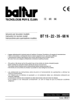
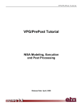
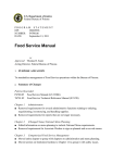
MODEL DV 270.2
Door-Type High Temperature Sanitizing Pot and Pan Washer
(USA Version)
OWNER’S INSTALLATION, OPERATION
MAINTENANCE MANUAL
AND
Meiko • 917 Airpark Center Drive • Nashville, TN 37217 • Phone: (615) 399-6600 • (800) 55-MEIKO • Fax: (615) 399-6620
Rev. 12/06
TABLE OF CONTENTS
1. INTRODUCTION ................................. 3
1.1 Overview of Equipment ............................. 3
1.2 General Safety Information........................ 3
2. TRANSPORT AND SHIPPING ............ 3
3. INSTALLATION .................................... 4
3.1 Overview of Installation ............................. 4
3.2 Requirements Before Installation .............. 4
3.3 Uncrating, Positioning and Leveling ............. 5
3.4 Accessing the Utility Connections ............. 5
3.5 Main Electrical Supply Connection ............ 6
3.6 Dispensing System Overview .................... 7
3.7 Installing an External Detergent System ... 8
3.8 Installing an External Liquid Rinse
Aid System ................................................ 9
3.9 Wiring External Chemical
Dispensing Systems .................................. 9
3.10 Connecting Chemical Containers
or Dispensers .......................................... 10
3.11 Fresh Water Supply Connection .............. 11
3.12 Drain Hose Positioning ............................ 11
3.13 Tabling Attachment .................................. 12
3.14 Final Assembly ........................................ 13
3.15 Priming the Liquid Detergent and
Rinse Additive Lines ................................ 13
3.16 Checking for Correct Chemical
Concentration .......................................... 13
4. OPERATION ....................................... 15
4.1 Location and Description of Controls ....... 15
4.2 Startup ..................................................... 16
4.3 Loading .................................................... 16
4.4 Operation ................................................. 18
4.5 Between Cycles ....................................... 18
4.6 Shutdown ................................................ 18
5. CLEANING ......................................... 19
5.1 Daily Cleaning (or as required) ................ 19
5.2 Weekly Cleaning (or as required) ............ 20
5.3 Exterior Cleaning (as required) ................ 21
5.4 Deliming (as required) ............................. 21
6. TROUBLESHOOTING ........................ 22
AN ELECTRICAL WIRING DIAGRAM IS LOCATED INSIDE THE
LOWER-FRONT COMPARTMENT OF THIS MACHINE.
THE MEIKO MODEL DV 270.2 HAS BEEN DESIGNED EXCLUSIVELY
FOR THE WASHING OF POTS, PANS, TRAYS, KITCHEN UTENSILS, CUTLERY,
DISHES AND GLASSWARE IN A COMMERCIAL OR INSTITUTIONAL SETTING
AND MUST NOT BE USED FOR ANY OTHER PURPOSE.
MEIKO ACCEPTS NO RESPONSIBILITY FOR DAMAGE TO THE APPLIANCE, SURROUNDING
EQUIPMENT OR ENVIRONMENT THAT IS CAUSED BY INAPPROPRIATE INSTALLATION OR
OPERATION, OR FROM ANY SERVICE THAT IS UNDERTAKEN BY NON-AUTHORIZED
PERSONNEL, OR FROM THE USE OF ANY PARTS EXCEPT THOSE THAT ARE APPROVED BY THE
MANUFACTURER. ANY SUCH INSTALLATION, USE OR SERVICE WILL IMMEDIATELY VOID THE
MANUFACTURER’S WARRANTY.
ANY MODIFICATIONS TO THE APPLIANCE THAT ARE PERFORMED WITHOUT THE WRITTEN
PERMISSION OF MEIKO WILL IMMEDIATELY VOID THE MANUFACTURER’S WARRANTY.
Meiko reserves the right to change any specifications without notice at any time.
Meiko • 917 Airpark Center Drive • Nashville, TN 37217
Phone: (615) 399-6600 • (800) 55-MEIKO • Fax: (615) 399-6620
www.meiko.us
Page 2
SECTION 1 - INTRODUCTION
1
INTRODUCTION
1.1 Overview of Equipment
The Meiko Model DV 270.2 is a commercial
pot and pan washer/dishwasher. It is designed
for cleaning pots, pans, trays, kitchen utensils,
cutlery, dishes and glassware with a minimum
of employee intervention or supervision.
A control keypad allows easy selection of
three different washing cycles to accommodate different types of ware and levels of
soiling. A digital display permits easy
monitoring of operation.
Other features of the unit that affect operation
include:
Auto Safe - An internal booster heater is
controlled by the electronic control system to
ensure proper wash and rinse temperatures,
regardless of the incoming water supply.
Soft Start - The wash water is pumped at a
reduced pressure for the first few seconds of
the wash cycle. This protects the ware from
being moved or damaged by a sudden burst
of pressure.
Pumped Rinse - An internal rinse pump
ensures that the final rinse pressure is
constant.
Pumped Drain - Accommodates wall or floor
drains.
Aqua Stop - The unit will automatically shut
down if a water leak is detected.
For efficient and SAFE operation, be sure to
follow the installation and operating instructions provided in this manual. In particular, all
safety symbols and notices on the equipment
and in the supplied documentation must be
followed.
IMPORTANT
The Model DV 270.2 has been designed
exclusively for the washing of pots, pans,
trays, kitchen utensils, cutlery, dishes and
glassware in a commercial or institutional
setting and must not be used for any other
purpose.
1.2 General Safety Information
The following symbols and headings are used
throughout this manual to indicate possible
hazards to persons or to the equipment. The
symbols and headings are shown in order of
importance. The descriptive text following these
headings is italicized for easy recognition.
WARNING!
Possible hazard to persons, such as from electrical shock, crushing, or
hot surfaces.
CAUTION
Possible hazard to the
dishwasher or to other
equipment.
IMPORTANT
Vital information or tips for
the installer or operator.
NOTE
Information or tips for the
installer or operator.
2
TRANSPORT AND SHIPPING
IMPORTANT
• Observe any notices on the crating
material that pertain to shipping.
• Use care when transporting the
equipment.
• As you unpack the equipment, check that
all components shown on the shipping
invoice are present and intact. Be sure to
check for shipping damage. If shipping
damage is present, call Meiko Customer
Service at 1-800-868-3840, providing full
details on the customer, serial number and
extent of damage present. Meiko will file
a freight claim based on this information.
WARNING!
In NO EVENT should a damaged
appliance be installed or operated!
Page 3
SECTION 3 - INSTALLATION
3
INSTALLATION
3.1 Overview of Installation
The owner should contract with qualified
personnel to move the appliance to the
installation location, unpack it, and prepare it
for final utility connections. In most cases,
local codes prevent the final utility connections
from being made by any party other than a
licensed electrician and/or plumber.
IMPORTANT
It is the responsibility of the owner to ensure
that all aspects of the installation comply with
all applicable local and national codes.
IMPORTANT
The appliance’s warranty is not valid until a
Meiko Authorized Service Agent performs a
Startup and Demonstration on the appliance.
This Demonstration should be scheduled after
installation.
Installation of the machine involves the
following steps:
• Verifying that the utility connections are
present, are appropriate for the appliance,
and comply with all applicable local and
national codes.
• Unwrapping the appliance (leaving the
shipping skid in place for easier movement) and checking for shipping damage.
• Moving the appliance to the installation
location, removing the skid, and leveling
the feet.
• Connecting the electrical supply.
• Installing the chemical dispensing system.
For units equipped with the optional
dispensing system, this involves
connecting the machine’s detergent and
rinse additive tubes to appropriate dispensers.
For units without the optional system, the
dispensing system installer should follow
the manufacturer’s instructions AND the
instructions in Section 3 of this Manual.
• Connecting the fresh water supply.
• Positioning the drain hose.
• Connecting the machine to tabling.
Page 4
•
Contacting your Meiko Authorized Service
Agent to perform a Startup and
Demonstration on the appliance. This step
also validates the appliance’s warranty.
3.2 Requirements Before Installation
Before the installer can uncrate and move the
appliance to the installation location, the
following conditions MUST be met:
• INSTALLATION AREA REQUIREMENTS
- The area MUST be frost-free. Freezing
temperatures (32°F/0°C or lower)
inhibit proper operation and can
damage internal components.
- The area MUST have a firm floor
surface. It is possible to compensate for
uneven flooring by adjusting the feet.
- The area should be away from
appliances, furniture or surfaces that
can be damaged by steam. If this is
not possible, these items should be
protected from the small quantities of
steam that are released during normal
operation of the machine.
• UTILTITY CONNECTION REQUIREMENTS
- Connections must be present and
ready for hookup to the appliance. All
utility supplies must comply with the
electrical information labels, with the
information on the data plate, and with
all applicable local and national codes.
- Electrical leads and the water supply
hose (supplied by the customer) must
be present.
- For units without the optional
dispensing system, external detergent
and rinse additive pumps (if used)
should be installed according to the
manufacturer’s instructions.
- For units with the optional dispensing
system, appropriate dispensers or
containers should be installed and
ready for connection to the appliance.
• GENERAL REQUIREMENTS
Authorized personnel should be available
to perform the actual utility connections.
SECTION 3 - INSTALLATION
3.3 Uncrating, Positioning and Leveling
1. Remove all shipping and packaging material
from the appliance, including supports and
wrappings. Leave the shipping skid in place
at this time to allow for easier movement to
the installation location.
2. Check for shipping damage as described
in Section 2, “Transport and Shipping.” If
damage is present, call Meiko Customer
Service at 1-800-868-3840, providing full
details on the customer, serial number and
extent of damage present. Meiko will file a
freight claim based on this information.
3. Move the appliance to the installation area
and remove the skid. Use caution to avoid
damaging the appliance or any of its
components.
4. Using a spirit level, check that the appliance
is level in both directions (front-to-back AND
side-to-side). If necessary, level the
appliance by rotating the bottom section of
each foot.
CAUTION
The machine MUST be level for proper
operation.
3.4 Accessing the Utility Connections
Water supply and drain connections are located
at the lower rear of the machine. The electrical
supply enters through a strain relief at the lower
rear, but the terminal blocks are accessed from
the front of the machine.
To remove the lower front panel:
1. Remove AND RETAIN the four (4) screws
on the bottom edge of the lower front panel.
See Figure 3-1.
2. Slide the panel down and away from the
machine to remove it. As you pull the panel
away, disconnect the ribbon cable for the
Mike 2 controller to avoid damage.
3. The terminal blocks for the main electrical
supply and chemical dispensers (if used)
are located on the left side of the machine
as shown in Figure 3-2.
Figure 3-1
SELEC
NORM T
CYCLAL
P
POW
OW
ER
ER
E
O
SELEC ON
N
EXTEN
T
CYCLDED
E
SELEC
HEAVYT
CYCL
E
S
STAR
TAR
C
CYCL T
T
YCL
or E
E
or
D
DRAI
W
W
ASH
ASH
T
TEMP
EMP
MIN
RAI
N
N
P
POW
OW
T
T
ERA
ANK
ERAANK
. 150° TUR
TUR
F/66 EE
°C
ER
O
OFFER
FF
F
FINA
INA
T
TEMP
L
EMPL
MIN
R
R
INS
ERA
ERAINS
E
E
. 180° TUR
TUR
F/82 EE
°C
Remove
4 screws on
bottom edge
As panel is
removed,
disconnect
ribbon cable to
Mike 2 controller
Figure 3-2
Main
electrical
supply
terminal
block
Chemical
dispenser
terminal
block (if
used)
Page 5
SECTION 3 - INSTALLATION
3.5 Main Electrical Supply Connection
WARNING!
Check that the circuit breaker/fused
disconnect is in the OFF position and
that the unit is switched off before
making the electrical utility connections.
IMPORTANT
In some cases, local codes dictate that
electrical supply connections be made only
by a certified professional.
1. Check that the incoming power leads are
of sufficient rating for the appliance’s
current draw. Amperage and minimum
supply wire specifications are shown on
the serial plate and on the electrical
information label next to the main terminal
block.
2. Check that the incoming power leads are
long enough to permit the unit to be
repositioned for servicing.
3. Locate the strain relief for the electrical
supply wiring at the lower rear of the
machine (Figure 3-3). Thread the
incoming supply leads through the strain
relief and to the main electrical supply
terminal block at the front of the machine
(Figure 3-4).
4. Refer to Figure 3-5 and the electrical wiring
diagram. Connect the power supply and
ground leads as indicated.
5. Adjust the strain relief to fasten the wiring
in place. You should leave enough slack
in the wiring to prevent stress on the
terminal connections.
Figure 3-3: Utility connections
Figure 3-4: Routing the
electrical supply
Lower rear
of machine
Main
electrical
supply
terminal
block
Fresh water
connection
Liquid detergent and
rinse additive supply
lines (if so equipped)
Drain
hose
Electrical
supply
strain relief
Lower front
of machine
Figure 3-5: Main electrical supply connections
L1
Page 6
L2
L3
G
N
D
208-230V, 60Hz, 3 Phase
or
460V, 60 Hz, 3 Phase
L1, L2 and L3 “hot” (line)
yel/grn = ground
SECTION 3 - INSTALLATION
3.6 Dispensing system overview
The DV 270.2 is designed for use
with a liquid rinse aid, and either
solid or liquid detergents.
Units equipped with optional liquid
internal detergent and rinse aid
pumps have two tubes exiting the
machine at the lower rear. These
tubes can simply be attached to
detergent and rinse aid containers.
See Figure 3-6.
Units that are NOT equipped with
the internal pumps have:
• A blue rinse aid line exiting the
machine at the lower rear.
• Two dummy plugs covering
holes in the back of the wash
tank that can be used for detergent injection. The plugs are
accessed by removable panels
on the sides of the machine.
Either plug can be used.
• A hole in the bottom of the wash
tank for the installation of a detergent concentration probe.
A dispensing system terminal block
(shown in Figure 3-6) provides
contacts for two line voltage
relays. These relays, when closed,
provide a “window” for external
pump systems to activate.
• The rinse aid pump relay closes
for approximately 16.5 seconds
whenever the booster tank
refills (once per cycle).
• The detergent pump relay
closes whenever the wash
pump is in operation.
Activation of the pumps can be
controlled as follows:
• Solid detergent systems should
use a detergent concentration
probe installed in the wash tank
to activate the external pump.
A dummy plug at the bottom of
the wash tank provides an
installation location for the probe.
Figure 3-6: Chemical connections
Liquid detergent
injection (clear)
- only present
on machines
with internal
chemical pump
option
Access panel for
external chemical
dispenser injection
(use either side)
Liquid rinse
additive injection
(blue)
Dummy plugs
for detergent
injection
(use either side)
Dummy plug
for detergent
concentration
probe
Level
sensor
Main electrical
supply terminal
block
•
•
Chemical
dispenser
terminal block
Liquid detergent systems can use EITHER a
detergent concentration probe, OR a timer system.
A detergent concentration probe is HIGHLY
RECOMMENDED.
Liquid rinse aid systems should be controlled using
a timer system.
Page 7
SECTION 3 - INSTALLATION
CAUTION
If the unit will NOT use one or both of
the chemical supply tubes, cut the
unused tube(s) close to the point
where it exits the machine’s exterior
panel and seal it using the supplied
plug and wire clamp. See Figure 3-7.
For units equipped with the optional
internal chemical dispensing system,
skip ahead to Section 3.10, “Connecting Chemical Containers or Dispensers.”
3.7 Installing
an
External
Detergent System
To install a detergent dispensing
system:
1. Remove the detergent plug access
panel on either side of the machine.
Remove the matching dummy plug
from the back of the wash tank.
See Figure 3-8.
2. Route the detergent supply line
through one of the two holes in the
access panel, through the side
panel, and into the wash tank. For
solid systems, use the large hole
in the access panel. For liquid
systems, use the smaller hole.
3. Fasten the line in place and seal
the connection.
4. Replace the access panel.
5. If a detergent concentration probe
will be used, remove the dummy
plug in the bottom of the wash tank.
Then, install the detergent
concentration probe and seal the
connection. See Figure 3-8.
6. Check that the pump is correctly
installed according to the manufacturer’s instructions.
Page 8
Figure 3-7: Sealing unused chemical tubes (if
not using a liquid detergent or rinse additive)
Cut
tubing
Seal with plug
and wire clamp
Figure 3-8: External detergent system
Access
panel for
external
chemical
dispenser
injection
Remove dummy
plug to attach
detergent supply line
Remove large plug to
route solid detergent
supply line
OR
Remove small plug to
route liquid detergent
supply line
Remove dummy plug to
install detergent
concentration probe
(if using a probe)
SECTION 3 - INSTALLATION
3.8 Installing an External Liquid Rinse
Aid System
A pre-plumbed, blue 1/4” ID tube at the
lower rear of the unit serves as the
connection point for the rinse aid supply.
See Figure 3-9.
If a liquid rinse aid system will NOT be
used, cut the tubing near the rear panel.
Then, close and seal it with the plug and
wire clamp that are supplied on the end
of the tube. See Figure 3-7.
To install a liquid rinse aid dispensing
system:
1. Route the rinse aid supply line to the
blue 1/4” ID tube at the lower rear of
the machine.
2. Fasten the line in place and seal the
connection.
3. Check that the pump is correctly
installed
according
to
the
manufacturer’s instructions.
3.9 Wiring External Chemical Dispensing Systems
IMPORTANT
Some local codes dictate that electrical
connections be made only by a certified
professional.
1. Locate the chemical dispenser
terminal block. See Figure 3-4.
2. Thread the incoming leads from the
chemical pumps through the extra
strain reliefs (at the lower rear of
machine) and to the chemical
dispenser terminal block.
3. Connect the wires as shown in Figure
3-10. Note that the terminal block
supplies LINE VOLTAGE SIGNALS.
An additional transformer may be
required depending on the supply
requirements of the external pumps.
4. Adjust the strain reliefs to fasten the
wiring in place. Leave enough slack in
the wiring to prevent stress on the
terminal connections. Bundle the wires
together using wire ties to prevent
them from tangling when repositioning
the appliance.
Figure 3-9: Liquid rinse additive system
Liquid rinse
additive
injection (blue)
Figure 3-10: Dispenser pump wiring
Page 9
SECTION 3 - INSTALLATION
3.10 Connecting Chemical Containers or
Dispensers (if so equipped)
This section applies to units with either
internal or external chemical dispensing
pumps.
1. Check that the rinse additive and
detergent are compatible with the unit. In
particular, a commercial (not a domestic)
detergent MUST be used.
2 Check that the containers/dispensers are
correctly installed according to the
manufacturer’s instructions.
3. If the dishwasher is equipped with factory
internal chemical dispensing pumps, two
strainer assemblies for the chemical
containers are also included. See Figure
3-11. These strainers should be
assembled onto the lids for the detergent
and rinse additive containers.
4. For liquid detergent systems, locate the
CLEAR liquid detergent tube. Connect the
tubing to the detergent container.
For solid detergent systems, connect the
detergent supply line according to the
manufacturer’s instructions.
5. Locate the BLUE liquid rinse additive tube
at the lower rear of the unit. Connect the
tubing to the rinse additive container.
6. If using the strainers shown in Figure
3-11, be sure to use the supplied wire
clamps to fasten the chemical supply
tubes securely. Meiko STRONGLY
RECOMMENDS the use of a sealing
compound on these connections to
prevent leakage.
Figure 3-11: Strainer assembly
Wire
clamp
Lid for detergent
or rinse additive
container
Strainer
tube
Page 10
SECTION 3 - INSTALLATION
3.11 Fresh Water Supply Connection
CAUTION
Before connecting the water supply hose, the
line MUST be flushed clean of all debris,
including (but not limited to) pipe sealant,
metal particles, solder, etc. This debris can
damage the appliance.
IMPORTANT
In some cases, local codes dictate that water
supply connections be made only by a
certified professional.
1. Check that iron or other metal particles
cannot contaminate the fresh water
supplied to the dishwasher.
2. Check that the incoming water pressure
is within the acceptable range for the
appliance (8.7-72.5 psi, 0.6-5.0 bars). It
may be necessary to increase the pressure (with a booster pump) or to reduce
the pressure (with a reducing valve).
3. Check the incoming water temperature.
Meiko recommends a water temperature
of 140°F/60°C for optimum operation,
although if necessary the appliance will
operate correctly using water at any
temperature of 140°F/60°C or lower.
Colder water will result in a longer preheat
time (during initial startup) and may extend
the cycle time to allow the final rinse water
to heat to 180°F/82°C.
4. Check the incoming water hardness.
Meiko recommends a hardness of 4 grains
per U.S. gallon (7 DH German hardness).
Figure 3-12: Fresh water supply and
drain connections
5. Because the water inlet incorporates a
stainless steel dirt trap, an additional trap
is unnecessary unless required by local,
national or international codes.
6. The dishwasher includes a water supply
line that ends in an enclosure containing
the water inlet valve and the Aqua-Stop
shutoff valve (see Figure 3-12). Connect
the customer-supplied water line to the
fitting on the end of this enclosure. Use a
sealing compound on the threads to ensure
that no leaks are present in the connection.
7. Check that the water line is long enough
to permit the unit to be repositioned for
servicing.
3.12 Drain Hose Positioning
1. Check that the end of the drain hose will
empty into a drain with a minimum
diameter of 1-1/2”/38mm.
2. Check the type of drain that will be used.
Because the DV 270.2 uses a pumped drain,
either a floor or wall drain is acceptable.
CAUTION
No portion of a wall drain system may be
higher than 24” (610m) A.F.F. to ensure
that the drain pump is operating within
rated specifications. See Figure 3-13.
3. Route the drain hose to the drain. In some
cases, a grease trap (supplied by others)
must be fitted into the waste water line. If
this trap is required for your installation,
check that it is present.
Figure 3-13: Drain line
vertical rise limitations
Lower rear
of machine
Fresh water
connection
Drain
hose
No portion of
drain system
may be higher
than 24”
(610mm)
A.F.F.
Page 11
SECTION 3 - INSTALLATION
3.13 Tabling Attachment
1. Position the machine and tables
as follows:
• Check that the centerline of the
opening at the end of each table
is aligned with the centerline of
the basket track of the machine.
See Figure 3-14.
• Check that the surface height
of each table matches the
height of the basket track of the
machine, to ensure a smooth
transition. The standard table
surface height is 34” (864mm).
• Check that the machine is level.
The height of the machine, and
of most tables, can be adjusted
by rotating the feet at the end
of the legs.
CAUTION
After adjusting the height of the
machine, always check that it
is level to ensure proper operation.
Figure 3-14: Aligning the table
centerlines with the machine
Centerline of
table opening
Centerline of
basket track
Figure 3-15: Tabling attachment
Lip-in flange MUST
be flush against the
vertical mounting
surface
2. Position each table lip-in at the
machine, as shown in Figure
3-15. Be sure to seat the lip-in
against the inner, vertical
mounting surface.
CAUTION
If the table lip-in extends
beyond the vertical mounting
surface, and down to the angled
face of the inside of the
machine, it will not seat
properly. The lip-in should be no
more than 3/4” (19mm) in depth
to ensure correct mounting to
the machine.
3. After the tables have been
positioned correctly, secure
them to the machine using
silicone sealant.
Page 12
Lip-in flange MUST
NOT extend to the
angled face inside
the machine
Turndown
lip-in
flange
3/4”
(19mm)
max.
2’ 4”
(711mm)
SECTION 3 - INSTALLATION
3.14 Final Assembly
1. Check and tighten all electrical terminal
screws.
2. Replace all panels onto the machine.
3. Switch the circuit breaker/fused
disconnect to the ON position. Be sure to
prime the detergent pumps and check for
correct chemical concentration before
operating the unit.
3.15 Priming the Detergent and Rinse
Additive Lines
For machines equipped with external
chemical dispensing systems, prime the
detergent and rinse additive lines according
to the manufacturer’s instructions.
For machines equipped with factory internal
chemical dispensing systems, prime the lines
as follows:
1. Press and hold the
key until
appears in the display
(about 4-5 seconds).
2. Press the
key 5 times until
appears in the display.
3. Press the
key.
appear in the display.
will
4. Press the
key to start priming the liquid
rinse additive lines. A timer will count down
the time remaining. By default, the system
will prime for 180 seconds.
5. When
the
that
display.
display returns to
, press the
key so
appears in the
6. Press the
key to start priming the liquid
detergent lines. A timer will count down
the time remaining. By default, the system
will prime for 30 seconds.
7. When
the
display returns to
, press the
key to
shut off the dishwasher.
3.16 Checking for Correct Chemical
Concentration
Machines equipped with external chemical
dispensing systems will have normal settings
recommended by the manufacturer.
For machines equipped with factory internal
chemical dispensing systems, the normal
settings for chemical injection are:
• Detergent - 0.256 oz. per gallon of wash
water (2.0 ml per liter).
• Rinse additive - 0.0256 oz. per gallon of
rinse water (0.2 ml per liter).
To check if the normal settings are correct for
your chemicals, RUN THREE EMPTY
LOADS to completely cycle the water supply
and obtain accurate test results. This will only
take a few minutes. Then, run a sample load
with soiled ware and examine the results.
• If the detergent setting is too low, the ware
will not be adequately cleaned. In some
cases, this can be corrected by simply
selecting a longer cycle time (using the
Cycle Select II, Medium or Cycle Select
III, Heavy buttons), but the detergent
concentration may also need to be adjusted.
• If the rinse additive setting is too low,
spotting or streaking may occur on the
ware.
• If too much of either chemical is added,
the extra chemicals will be wasted. This
is often difficult to detect except by
determining how long your chemical
supplies last. If the chemicals are being
exhausted quickly, you may need to have
the chemical concentration adjusted.
IN ALL CASES, ANY ADJUSTMENTS OF
THE FACTORY CHEMICAL INJECTION
SETTINGS ARE TO BE PERFORMED
ONLY BY A MEIKO AUTHORIZED
SERVICE AGENT. CHANGES BY
UNAUTHORIZED PERSONNEL WILL
VOID YOUR WARRANTY.
If you need to contact your Authorized
Service Agency, please contact Meiko
Technical Support at 1-800-868-3840.
Page 13
SECTION 3 - INSTALLATION
Notes
________________________________________________________________________________
________________________________________________________________________________
________________________________________________________________________________
________________________________________________________________________________________________________________________________________________________________
________________________________________________________________________________________________________________________________________________________________
________________________________________________________________________________________________________________________________________________________________
________________________________________________________________________________________________________________________________________________________________
________________________________________________________________________________________________________________________________________________________________
________________________________________________________________________________________________________________________________________________________________
________________________________________________________________________________________________________________________________________________________________
________________________________________________________________________________________________________________________________________________________________
________________________________________________________________________________________________________________________________________________________________
________________________________________________________________________________________________________________________________________________________________
________________________________________________________________________________________________________________________________________________________________
________________________________________________________________________________________________________________________________________________________________
________________________________________________________________________________________________________________________________________________________________
________________________________________________________________________________________________________________________________________________________________
________________________________________________________________________________________________________________________________________________________________
________________________________________________________________________________________________________________________________________________________________
________________________________________________________________________________________________________________________________________________________________
________________________________________________________________________________________________________________________________________________________________
________________________________________________________________________________________________________________________________________________________________
________________________________________________________________________________
Page 14
SECTION 4 - OPERATION
4
OPERATION
4.1 Location and Description of Controls
The machine controls are on the keypad on the front panel. See Figure 4-1.
Figure 4-1: Dishwasher controls
A
B
C
D
P
N
ON
OWER O
POWER
SELECT
NORMAL
CYCLE
SELECT
EXTENDED
CYCLE
W
ANK
TANK
ASH T
WASH
T
EMPERATURE
TEMPERATURE
F
INSE
RINSE
INAL R
FINAL
T
EMPERATURE
TEMPERATURE
MIN. 150°F/66°C
MIN. 180°F/82°C
F
A, B, C - POWER/CYCLE SELECT keys
These keys turn the machine on. Each key
selects a different cycle length to
accommodate differing levels of soiling:
Normal cycle (3 minutes) for plates,
glassware and typically soiled pots,
pans and utensils
Extended cycle (5 minutes) for items
with heavier soiling
Heavy cycle (8 minutes) for items
with very heavy soiling
The keys may also be pressed between
cycles to choose a different cycle length.
D - CYCLE/DRAIN key
If pressed when the unit is
ready to operate, this key
starts the operating cycle. If
the machine has been
switched off (for instance, at the end of the
shift), this key empties the tank.
SELECT
HEAVY
CYCLE
E
S
TART
START
C
YCLE
CYCLE
or
or
D
RAIN
DRAIN
P
OWER
POWER
O
FF
OFF
G
E - POWER OFF key
If pressed when the unit is in
operation, this key ends the cycle
immediately. If the unit is NOT in
operation, this key will switch the unit off.
F - WASH TANK TEMPERATURE display
Shows the current
temperature of the
water in the wash tank.
G - FINAL RINSE TEMPERATURE display
Shows the current
temperature of the
final rinse water. The machine cannot begin
a rinse cycle until the rinse water has heated
to the proper temperature. The wash cycle
will automatically extend (if necessary) until
the proper rinse temperature is reached.
Page 15
SECTION 4 - OPERATION
4.2 Startup
4.3 Loading
Check the level of the external detergent and
rinse additive dispensers. If necessary,
replace or refill the dispensers.
The loading guidelines shown here will lead
to faster, more efficient cleaning of your ware.
Press any of the three POWER/CYCLE
SELECT keys to turn on the machine.
Normal cycle for plates, glassware and
typically soiled pots, pans and utensils
Extended cycle for items with
greater soiling
Heavy cycle for very heavily soiled
items
The light above the selected
POWER/CYCLE SELECT key will
begin to flash, showing that the tank
is filling and the water is heating to
the correct temperature.
The time required for filling and preheating
will vary based on the temperature of the
incoming water supply. For incoming water
at 140°F/60°C, the machine may need up to
30 minutes to fill and heat to the correct wash
temperature. The default wash temperature
is several degrees above 150°F/66°C for
efficient operation.
Load sheet pans, trays, etc. at an angle with
the inside face pointing up. Use the triangular
sheet pan support insert for these items for
faster loading, and to ensure that the ware is
positioned and spaced properly for effective
washing.
Pans and trays
loaded at an angle
with the inside
facing UP
Sheet pan
support insert
(flashing)
Load pots, bowls or deep pans with the open
side facing down. If items are too light to stay
in position, place the chain mesh on top of
them to prevent movement during the wash
cycle.
Chain
mesh
OPTIONAL
If desired, you can watch the WASH TANK
TEMPERATURE and FINAL RINSE TEMPERATURE displays as they rise. This gives
an indication of the amount of time left before the machine can be operated.
(constant)
Page 16
When the tank is full and the water
has been heated to the correct
temperature, the light above the
selected POWER/CYCLE SELECT
key will stop flashing. The machine
is now ready for operation.
Pots, bowls and
deep pans
loaded with the
open side facing
DOWN
SECTION 4 - OPERATION
Plates, soup bowls, and glassware can be
loaded into the machine using standard
20x20” racks. The DV 270.2 wire basket holds
two racks. Be sure to align the racks with the
locator guides in the bottom of the wire basket.
Glasses loaded
with the open side
facing DOWN
Locator
guides
Glassware
rack
Two
20x20”
racks
OR
Rack with
hold-down grid
For greater efficiency in loading cutlery, you
can use cutlery holders. When loading them:
When loading 20x20” racks, load plates, soup
bowls, etc. at an angle with the inside face
pointing up. Ensure that water cannot pool in
the bottom of bowls. Loading bowls face-up
reduces the possibility of movement during
the wash cycle.
Position bowls
to allow water
to drain
Plates and bowls loaded
at an angle with the
open side facing UP
Glasses should be loaded with the open side
facing down, using EITHER a rack with a holddown grid, OR a tall, compartmentalized rack
intended for glassware, to prevent movement
during the wash cycle.
•
•
•
Do not overload the holders.
Always load knives, forks and
spoons with the handle
DOWN.
Do not load identical ware
into any given holder.
Instead, load an assort-ment
of knives, forks and spoons
into each holder. Identical
ware is often too closely
spaced for effective cleaning.
Do not stack items in the machine. Stacked
items require longer or multiple cleaning
cycles because the wash water cannot reach
the food residue as effectively.
After loading, roll the
basket into the machine
until the wheels settle
into the depressions in
the rack rails. Then, pull
down on the handle to
close the door.
Page 17
SECTION 4 - OPERATION
4.4 Operation
Press the CYCLE/DRAIN key to
begin the selected cycle. The key
will not work unless the light
above the selected POWER/
CYCLE SELECT key has stopped
flashing.
The machine will begin a wash and rinse
cycle. The Soft Start feature pumps the water
through the arms slowly for the first few
seconds of the cycle to protect fragile ware.
After a few seconds, full pressure will engage.
The time of the total cycle will be at least as
long as the times shown in Section 4.1. When
using a cold water supply, the machine will
automatically extend the wash cycle if
necessary until the final rinse water can be
heated to the correct temperature.
OPTIONAL
If desired, the cycle can be stopped at any
time by pressing the POWER OFF (
)
button OR by opening the door.
WARNING!
If the door is opened suddenly, hot
water can spray out of the machine. To
prevent this from happening:
• Open the door slowly until the machine
stops operating, OR
• Press the
key to stop the wash/rinse
cycle before opening the door.
When the cycle has completed, the machine
will stop operating and sound a three-stage
beeping tone. After the tone has sounded, you
may lift the handle to open the door, roll out
the basket, and unload the ware. Note that
some steam will escape when the door is
opened; this is normal.
WARNING!
Use caution when handling hot
dishware.
Page 18
4.5 Between Cycles
Between cycles, leave the door of the
machine closed. If the door is left open, the
wash tank water will cool. This will activate
the tank heaters, consuming extra energy,
and may lengthen the recovery time when
another cycle is started.
If necessary, you can choose a different cycle
length between cycles by pressing any of the
POWER/CYCLE SELECT keys.
When you are ready to start a new cycle, refer
to Section 4.3, “Loading.”
4.6 Shutdown
At the end of the shift, press the
POWER OFF key.
Press the CYCLE/DRAIN key to
empty the tank.
After the water has drained, the machine will
enter a self-cleaning mode. The interior will
be sprayed with hot, fresh water as the
booster tank empties. When this is
completed, the drain will “pulse” several times
to empty the water and the dishwasher will
automatically shut off.
WARNING!
DO NOT open the door of the machine
during the self-cleaning process! The process
will be interrupted and hot water may spray
out of the machine.
After the machine has finished its selfcleaning cycle, open the door. Remove any
food particles, scraps or bones from the filter
screens. Meiko recommends that the door of
the dishwasher be left open overnight to allow
it to air thoroughly.
IMPORTANT
Because of the large quantity of food soiling
present on many pots and pans, it is
STRONGLY RECOMMENDED that the
interior of the machine be cleaned daily
following the instructions in Section 5.1, “Daily
Cleaning.”
SECTION 5 - CLEANING
5
CLEANING
5.1 Daily Cleaning (or as required)
1. The machine automatically enters a selfcleaning cycle when it is turned off. The
interior will be sprayed with hot, fresh
water as the booster tank empties.
2. AFTER this cycle ends and the machine
shuts down, open the door, and wheel the
basket out of the machine. Any food soil
clinging to corners, etc. of the basket can
be wiped off with a clean, damp cloth.
3. Remove the lower center wash arm to
access the scrap screen and wash tank.
To remove the arm, first pull its front side
up and out of the black retainer bar. Then,
pull the back side free of the manifold.
4 Remove any large food particles, scraps
or bones from the scrap screen.
5. Lift out the scrap screen and clean it
thoroughly using a brush and warm water.
6. Flip up the two angled plates that surround
the Active Plus filter.
7. Lift out the Active Plus filter. Clean it
thoroughly using a brush and warm water.
Be sure to use care to avoid damaging
the screen on the Active Plus filter.
WARNING!
Before ANY cleaning, check that the
circuit breaker/fused disconnect is in
the OFF position and that the unit is
switched off.
IMPORTANT
The headings Daily Cleaning and Weekly
Cleaning in this section are general
recommendations based on typical soiling.
Because of the large quantity of food soiling
present on many pots and pans, it may be
necessary to clean the machine more often
and more extensively than a traditional
dishwasher. Extensive food soil deposits
inside the machine work against optimal
performance. Some items may not be
cleaned as effectively, resulting in the need
for either a longer cycle or repeat washing. In
addition, heavy soiling in the wash water
increases detergent consumption.
Figure 5-1: Daily cleaning disassembly
Back of wash
arm is keyed
for correct
re-installation
ER
ER
T
T
TAREE
STAR
YCL
CYCL
or
or
N
N
RAI
DRAI
N
ON
ER
ER
OW
POW
T
T
SELEC
DED
EXTEN E
CYCL
SELECAL
NORM E
CYCL
EE
LL
ANKEE
TANK
ASH
ASH
TUR
TUR
ERA 6°C
W ERA
°F/6
EMP
TEMP
. 150
MIN
INS EE
RINS
TUR
TUR
INAERA
ERA 2°C
FINA
°F/8
EMP
TEMP
. 180
MIN
T
SELECY
HEAV E
CYCL
OW
POW
FF
OFF
Remove lower
center wash
arm to access
scrap screen
Scrap
screen
Active
Plus
filter
Flip up two angled
plates to access
Active Plus filter
Page 19
SECTION 5 - CLEANING
2. Remove and disassemble the wash and
rinse arms. The machine is equipped with:
• Five upper wash arms (identical)
• Five lower wash arms (identical)
• Two removable upper rinse arms
(identical)
• Two removable lower rinse arms (identical)
• Two additional fixed lower rinse arms
(leave these in place)
All four removable rinse arms are identical.
The upper wash arms are slightly longer
than the lower arms to prevent their reinstallation in the wrong location.
The lower wash arms are removed in the
same manner as the lower center arm
(see Section 5.1, “Daily Cleaning.”) To remove the upper wash arms, first pull the
front side of the arm down and out of the
black retainer bar, and then pull the back
side free of the manifold.
To remove the rinse arms, remove the retaining screw and pull the arm off the shaft.
3. Clean the wash and rinse arms with a
brush and warm running water. In particular, check that any food soil inside the
wash arms is removed.
4. Reassemble all components into the machine.
8. Check the inside of the wash tank for food
particles. Wipe any residue out of the tank
using a clean, damp cloth.
9. Meiko recommends that the door of the
machine be left open overnight to allow it
to air thoroughly.
10. Reassemble all components into the
machine before operation. Note that the
Active Plus filter MUST be re-installed with
the slotted end facing DOWN. See Figure
5-1.
IMPORTANT
Be sure to flip down the two angled plates
that surround the Active Plus filter before
replacing the scrap screen!
To replace the wash arm, first insert the
back end into the manifold. The back end
of the arm is keyed to ensure correct
replacement. Then, snap the front end
down into the black retainer bar.
5.2 Weekly Cleaning (or as required)
Once per week, or as required, perform the
following steps:
1. Follow the procedures in Section 5.1,
“Daily Cleaning.”
Figure 5-2: Wash and rinse arm disassembly
Four removable
rinse arms are
interchangeable
ER
ER
T
T
OW
POW
FF
OFF
TAREE
STAR
YCL
CYCL
or
or
N
N
RAI
DRAI
N
ON
ER
ER
T
SELEC
DED
EXTEN E
CYCL
OW
POW
T
T
SELECY
HEAV E
CYCL
SELECAL
NORM E
CYCL
LL
ANKEE
TANK
ASH
ASH
EE
EE
TUR
TUR
INS
RINS
INAERA
ERA 2°C
FINA
°F/8
EMP
TEMP
. 180
MIN
TUR
TUR
ERA 6°C
W ERA
°F/6
EMP
TEMP
. 150
MIN
Retaining
screw
Rinse
arm
Note that upper wash arms are longer than lower
wash arms to ensure correct re-installation.
Upper wash arm
Lower wash arm
Page 20
SECTION 5 - CLEANING
5.3 Exterior cleaning (as required)
5.4 Deliming (as required)
CAUTION
When cleaning the exterior of the machine,
be sure to follow these guidelines:
• Meiko strongly recommends using detergent when cleaning the exterior of the unit,
instead of commercial stainless steel
cleaners. These cleaners can damage the
surface of the control panel.
• Never use abrasive cleaners or pads when
cleaning the exterior of the machine.
These can scratch the surface of the unit.
WARNING!
Ensure that detergents and stainless
steel cleaners are kept out of the interior of the machine. If the interior of
the unit requires cleaning, refer to the
deliming procedures (Section 5.4).
Lime scale deposits will occur over time on
the interior of the machine if it is operated
using a hard water supply. Meiko recommends
a hardness of 4 grains per U.S. gallon (7 DH
German hardness).
A deliming or de-scaling process can be used
to remove these deposits, as well as any
accumulated food residue.
CAUTION
When deliming the interior, be sure to follow
these guidelines:
• Use deliming agents designed for use with
commercial dishwashers.
• Follow the instructions for the deliming
agent that is used.
After the deliming process:
1. Run the machine through 2-3 regular
cycles without a load to rinse and sanitize
the interior thoroughly.
2. Inspect the interior for any remaining
deliming agent residue. If residue is
present, remove it using a soft cloth and
hot water; then, run the machine through
one final empty cycle.
3. Press the POWER OFF
button; then,
press the CYCLE/DRAIN
button. This
will empty the tank, ensuring that any
deliming agent still in the tank will be
flushed out of the machine.
WARNING!
Ensure that ALL residue of the
deliming agent is removed. Residue
from the agent can:
- Pose a health hazard;
- Damage seals and plastic
components inside the machine.
Page 21
SECTION 6 - TROUBLESHOOTING
6
TROUBLESHOOTING
If the machine encounters a problem, an Info Code or Error Code will usually appear in the
display. If you use this troubleshooting guide to resolve simple problems, you can often return
the appliance to operation faster than placing a service call.
Info Codes appear for minor difficulties. Error codes appear for more complex issues. After
correcting the condition, if the unit does not return to normal operation automatically, press
or
to clear the message.
Display Shows
Problem
Action
Tank is not heating OR
fresh water is not
entering unit
Check that the water hose is correctly
attached and is free of “kinks” or
pinching. Also check that the water
supply is turned on.
Door is not closed OR
door switch is defective
Check that the door is completely
closed.
Water leakage onto floor
pan
Check that the water line to the unit is
not leaking, and that the drain hose
empties correctly into the floor drain.
Correct water level was
not reached during initial
filling
Check that the water hose is correctly
attached and is free of “kinks” or
pinching. Also check that the water
supply is turned on.
Filling process takes too
long
Check that the water hose is correctly
attached and is free of “kinks” or
pinching. Also check that the water
supply is turned on.
You should contact your Meiko Authorized Service Agent IF:
• The machine encounters a problem but does not display an error
code, OR
• An error code appears that is not shown here, OR
• The listed action fails to correct the problem.
An Authorized Service Agency Listing was supplied with your
machine. If you do not have the listing, call 1-800-868-3840 for
assistance.
Page 22
Notes
________________________________________________________________________________
________________________________________________________________________________
________________________________________________________________________________
________________________________________________________________________________________________________________________________________________________________
________________________________________________________________________________________________________________________________________________________________
________________________________________________________________________________________________________________________________________________________________
________________________________________________________________________________________________________________________________________________________________
________________________________________________________________________________________________________________________________________________________________
________________________________________________________________________________________________________________________________________________________________
________________________________________________________________________________________________________________________________________________________________
________________________________________________________________________________________________________________________________________________________________
________________________________________________________________________________________________________________________________________________________________
________________________________________________________________________________________________________________________________________________________________
________________________________________________________________________________________________________________________________________________________________
________________________________________________________________________________________________________________________________________________________________
________________________________________________________________________________________________________________________________________________________________
________________________________________________________________________________________________________________________________________________________________
________________________________________________________________________________________________________________________________________________________________
________________________________________________________________________________________________________________________________________________________________
________________________________________________________________________________________________________________________________________________________________
________________________________________________________________________________________________________________________________________________________________
________________________________________________________________________________________________________________________________________________________________
________________________________________________________________________________
Page 23
If you need service...
Meiko warewashers are designed for solid reliability as much as for
outstanding ware-cleaning ability. With proper care, your warewasher
should provide years of trouble-free operation.
If service is necessary, contact your local Meiko Authorized Service
Agent. With factory training, OEM parts and direct support from the
factory, Meiko’s nationwide service network is highly qualified to quickly
restore your warewasher to regular operation.
An Authorized Service Agency Listing is supplied with this Manual.
If you do not have the listing, call 1-800-868-3840 for assistance.
Meiko
917 Airpark Center Drive
Nashville, TN 37217
Phone: (615) 399-6600
(800) 55-MEIKO
Fax: (615) 399-6620