1
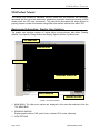
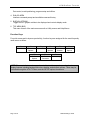
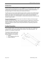
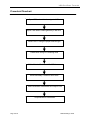
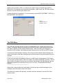
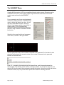
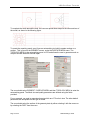
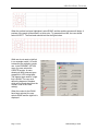
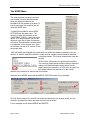
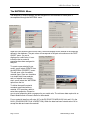
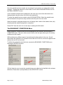
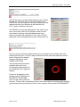
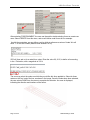
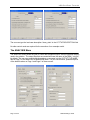
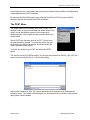
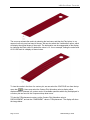
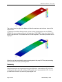
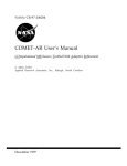
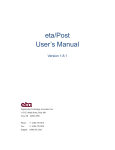
VPG/PrePost Tutorial
VPG/PrePost Tutorial
NISA Modeling, Execution
and Post Processing
Release Date: April, 2009
VPG/PrePost Tutorial
Engineering Technology Associates, Inc. assumes no liability or responsibility to any person or company
for direct or indirect damages resulting from the use of any information contained herein.
Engineering Technology Associates, Inc., ETA, the ETA logo, and eta/VPG are the registered trademarks
of Engineering Technology Associates, Inc. All other trademarks or names are the property of their
respective owners.
Copyright 1998-2009 Engineering Technology Associates, Inc. All rights reserved.
Engineering Technology Associates, Inc.
1133 E. Maple, Suite 200
Troy, Michigan 48083 USA
Phone:
(248) 729-3010
Fax:
(248) 729-3020
Support email: [email protected]
Page 2 of 22
NISA Modeling Tutorial
VPG/PrePost Tutorial
VPG/PrePost Tutorial
This tutorial was created to familiarize eta/VPG users with the functions and techniques
associated with the use of the construction, preparation, execution and post processing of NISA
models within the VPG user environment. This tutorial will demonstrate the steps required to
properly prepare a model for simulation using NISA finite element software from within VPG.
Background Information: Graphic User Interface
The graphic user interface consists of 6 areas within a single window: Main Menu, Drawing
Window, View Options, Dialog Window and Display Options and the Top Menu Area.
TOP MENU BAR
VIEW OPTIONS
MAIN MENU
DRAWING WINDOW
DIALOG WINDOW
DISPLAY OPTIONS
Figure 1: VPG User Interface
1. MAIN MENU: The Main menu options are displayed in this area after selections from the
TOP MENU BAR
2. DRAWING WINDOW
Display graphic entities (CAD- points, lines, surfaces; FEA- nodes, elements).
3. VIEW OPTIONS
Page 3 of 22
NISA Modeling Tutorial
VPG/PrePost Tutorial
Part control, model positioning, program setup and utilities.
4. DIALOG AREA
Interface command prompt and scrollable command history.
5. DISPLAY OPTIONS
Toggle ON/OFF graphic entities to be displayed and controls display mode.
6. TOP MENU BAR
This menu lists all of the main menus as well as Utility menus and Help Menus
Function Keys
For quick access and to improve productivity, function keys are assigned for the most frequently
used menus as follow:
F1
Clear Menu
F2
Element
Options
F7
Surface
Options
F3
Import File
F4
Line
Options
F8
PreProcessor
F5
Model
Checker
F6
Node
Options
F9
Online Help
NOTE: Please note that some images shown in this tutorial may make use of optional
display features including background colors, shading, and element outlines. These may be
controlled through the UTILITY Menu, and the SETUP options found there.
Page 4 of 22
NISA Modeling Tutorial
VPG Pre/Post Tutorial
Introduction
The NISA suite of software has been in use by engineers and scientists since the 1980’s, when
Engineering Mechanics Research Corporation (EMRC) first commercialized the product. Users
worldwide have used the NISA solver for automotive, aerospace, civil/structural problems,
taking advantage of the efficient data structure and accurate solution.
The NISA solver has been made available through an add-on module in the eta/VPG software
product. Static linear and normal modes solutions may be created and executed through the
eta/VPG user interface. This capability allows the user to perform stress and deflection
calculations on their structure, and the ability to calculate natural frequencies of their structures
using this simple interface.
The goal of this tutorial is to instruct the user in the method of creating, executing and post
processing a NISA simulation.
In order to automate this process a Drop Test Module has been implemented in eta/VPG that
allows the engineer to quickly define all necessary parameters used in a drop test, and by
allowing the engineer to create a series of drop test simulations, representing multiple test
configurations.
Problem Description
For our example problem, we’ll choose a simple structure that will allow use to define some
simple geometry, some easily created boundary conditions, and material properties. The
geometry of our example is shown below.
The bracket is fixed around the hole;
Load is added at the end of bracket;
Material properties are as following:
• Isotropic
• Young’s Modulus=3.0E+07 psi
• Poisson’s Ratio=0.3
Page 5 of 22
NISA Modeling Tutorial
VPG Pre/Post Tutorial
Procedural Flowchart
Open VPG and set database type to NISA
Import CAD data or create geometry in eta/VPG
Create PARTS using the proper element type
Create Mesh using VPG meshing tools
Define Material Models and Shell Thickness
Define Boundary Conditions and Loads
Define Simulation Parameters and Output Files
Output Model for Calculation
Page 6 of 22
NISA Modeling Tutorial
VPG Pre/Post Tutorial
Creating a NISA Model
For our example we will create geometry and construct a model for a static linear analysis.
To start our example, open a new VPG database. When you open the new database, select
NISA from the Main Menu. Optionally, this can be selected from the SETUP menu, in the
ANALYSIS PROGRAM menu selection. Selecting NISA will allow you to begin to define all of
the parameters necessary for a static linear analysis model.
It is expected that prior to entering the VPG software the user has some idea about:
•
•
•
Model geometry
Material properties and Thicknesses of the model parts
Type of output required from the analysis.
Start VPG and create a new database. Enter bar.vpg as the database name.
VPG will prompt “create a new database?” select
YES.
VPG will ask the user to select a database type,
defining the solver which will be used in the
simulation. Select NISA from the SELECY
ANALYSIS menu to set the element types, materials
and boundary conditions to those available in NISA.
In the empty database, we will import some
geometry, define elements, materials, boundary
conditions and control parameters.
The first step in creating a FE model with VPG is to create a PART entity. Parts can contain
geometry or elements. They don’t need to be representative of any physical entity. For instance,
you might have some geometry and some elements of your model in a part – not necessarily all
elements or geometry of a physical structure. Parts are a way for users to conveniently group
data in their model. However, most users will group the data in parts as a complete physical
structure; geometry and/or elements.
Since we have no geometry to import, we will create the geometry and then create a mesh on
that geometry data.
NISA models typically do not have a ‘part concept’, meaning that the element types and
properties are not grouped or assigned by part definitions. They are controlled by the element
definitions. However, for VPG users, the concept of parts is very normal and a convenient way
to manipulate the model data.
Page 7 of 22
NISA Modeling Tutorial
VPG Pre/Post Tutorial
When a part is created in VPG, it is necessary to create is using an element type (NKTP in
NISA terms). This identifies that the elements are beams, solids, shells, etc. VPG will not allow
the user to mix the element types within a part.
If a part will contain only geometry, it is not necessary to set the NKTP (ELEMENT TYPE ID) or
MID (MATERIAL ID) parameters.
Figure 2:
VPG Main Menu and
DTM Menu Location
The FILE Menu
The FILE menu provides the user access to functions which save, restart, import and export
models. The function that we will access is the IMPORT function. Under this function the user
can import CAD data or finite element model formats. There are native CAD interfaces for
commercial CAD software, and industry standard interfaces such as IGES and STEP formats.
If a commercial CAD interface is chosen, VPG will open a DOS window which will display the
results of the import of the data, and report the successful import or any errors which may have
occurred.
-------------------------------------------For our case we import the geometry of the bar in IGES format. We will select the FILE menu
from the upper left hand corner of the VPG window, and select the IMPORT command. The File
Open window will appear, and the user should select We will select the IGES file type from the
window drop down menu, and select “bar.igs” from our /VPG_Tutorials/PREPOST/NISA/
directory.
--------------------------------------------------------After the file is imported the user will be able to review any import-related messages in the
message area at the bottom of the VPG window.
This model now contains the geometry, surfaces and lines necessary to construct our finite
element model.
Page 8 of 22
NISA Modeling Tutorial
VPG Pre/Post Tutorial
The ELEMENT Menu
Creating NISA elements in VPG is accomplished through various means. Elements may be
created one at a time or for the entire model using the line and surface data. All element
creation tools are found in the ELEMENT
menu.
For our example, we will use a semi-automatic
method for creating elements. CREATE allows
users to define one element at a time. We will
use the 2-LINE MESH function, where we
define 2 lines between which we would like to
create a mesh. VPG will automatically
generate multiple elements between the lines
selected, using a number of elements defined
by the user.
Select the lines near the hole and a segment
of the hole, as shown in the figure below.
VPG will prompt the user for the number of elements to be generated. The first value is that
along the lines selected, the second number is the number of elements to be generated
between the selected lines.
Enter 4,2 – generating 4 elements along the selected lines, and 2 elements between the
selected lines. The resulting mesh is shown in the figure below. To accept the mesh, the user
selects YES from the menu when prompted to accept the mesh. If the user would like to abort or
remesh the model, they may select those options and restart the meshing operation.
Page 9 of 22
NISA Modeling Tutorial
VPG Pre/Post Tutorial
To complete the mesh around the hole, the user can repeat these steps for the other sections of
the model, as shown in the following figure.
To create the remaining mesh, we will use an automeshing tool which creates meshes on a
surface. This is found in the ELEMENT menus, under the SURFACE MESH menu. The
TOPOLOGY MESH is the automeshing menu in VPG and allows the user to generate mesh on
complex surface data with minimal repair.
The user should select ELEMENT / SURFACE MESH and then TOPOLOGY MESH to enter the
automeshing panel. The Mesh size and quality parameters are defined using the fields
provided.
For our example, we need to generate elements which are 0.75 units in size. The other default
parameters are acceptable for this type of model.
The user should select the surface of the geometry data by either selecting it with the mouse or
by selecting the PART from the menu.
Page 10 of 22
NISA Modeling Tutorial
VPG Pre/Post Tutorial
When the surface has been highlighted, select DONE, and the meshing process will begin. A
preview of the mesh will be shown in a white color. To generate this mesh, the user should
select ACCEPT. The final mesh should look like the figure below.
While we do not need a rigid link
in our example model, it is useful
to describe the method to create
one. In the ELEMENT OPTION
menu, the user selects the
CREATE function. A menu
showing all NISA element types
supported in VPG is displayed.
The element type used for a rigid
link is RLINK. The user must
define the degrees of freedom
which will be constrained from the
‘master’ node to the ‘slave’
node(s).
When the nodes for the RLINK
have been selected, the user
selects DONE and the rigid link is
displayed.
Page 11 of 22
NISA Modeling Tutorial
VPG Pre/Post Tutorial
The NODE Menu
The mesh has been created, but since it
was created in several individual steps,
there are duplicate nodes on the
boundaries of the meshes we created. To
identify and repair this condition, we will
enter the NODE menu.
To identify this condition, select NODE
OPTIONS from the main menu. The
function to check this condition is the
COINCIDENT CHECK – select this menu
option. VPG will prompt the user for the
tolerance it will use to check if nodes are
coincident. This should be a number small
in comparison to the element size. Since
our element size was 0.75, enter 0.05 into
the prompt area.
VPG will identify and highlight any nodes which are within this distance (resultant) from one
another. In order to repair this condition, nodes must be merged and the elements redefined
using these nodes. This is done automatically using this
function.
VPG will then offer options for repairing this condition.
The user may select specific nodes to merge, displayed
nodes or all identified nodes. Nodes will be moved
slightly during this operation, so VPG offers an option for
the certain nodes to be retained or for the central
position of the nodes to be used as the new location.
Select the ALL NODES option and the MIDDLE POSITION option for our example.
VPG will then prompt if you would like to merge and delete the now unused nodes, or if you
would like to merge the nodes and retain the now unused nodes.
For our example we will select MERGE and DELETE.
Page 12 of 22
NISA Modeling Tutorial
VPG Pre/Post Tutorial
The MATERIAL Menu
The definition of model materials, and the assignment of the materials to model parts is
accomplished through the MATERIAL menu.
When the user enters the MATERIAL menu, the model display will be indexed to the materials
defined in the database. The part colors will correspond to the part colors shown on the PART
ON/OFF menu. If a part is
displayed in a white color, it is an
indication that no material
properties have been assigned to
that part.
To create a new material for our
model, we will select CREATE from
the MATERIAL PROPERTY menu.
This will open a list of available
material types. Since our simulation
is a simple static linear analysis,
and our material is an isotropic
steel, we will select the *MATERIAL
option from the list.
To define the specific material
constants associated with our
material, VPG provides a table to
enter these properties. Please be
sure to enter properties which correspond to you model units. The minimum data required is an
Elastic Modulus and a Poisson’s Ratio for the material.
For our material (steel) we will enter 3e7 in the EX (ELASTIC MODULUS) field, and 0.3 in the
NUXY (POISSON’S RATIO IN X DIRECTION). When the data has been entered select OK to
accept the data and create the material.
Page 13 of 22
NISA Modeling Tutorial
VPG Pre/Post Tutorial
Once the material has been created, we may assign it to any parts in our mode which contain
elements. To apply this material to our bar model, we will select ASSIGN MATERIAL from the
MATERIAL PROPERTY menu.
A list of available materials will be displayed in the menu area, and will be referenced to the
displayed parts using the colors of the text in the material list.
To assign the material we just created, select ASSIGN MATERIAL. Select the material name
that was created in the previous step, and then select the part of our bar model.
When the material is assigned the part color will change from a white to the material color (red),
indicating that the material assignment is completed.
Please EXIT from this menu for our next step in creating the NISA model.
The BOUNDARY CONDITIONS Menu
Loads, pressures, constraints and enforced displacements are defined in the BOUNDARY
CONDITIONS menu. This menu allows users to define, edit and apply these types of boundary
conditions on their models.
NISA provides many different types of constraints and loading options for the user. We will
demonstrate the application of a constraint around the hole in our bar, and a force applied to the
nodes at the end of our bar model.
To define the constraints around the hole, we enter the BOUNDARY CONDITIONS menu,
selecting the SPDISP sub-menu.
VPG will allow the user to create the constraints as a set, which can be identified in the subcase
definitions. Please enter 1(accept default) for the SPDISP SET number.
Page 14 of 22
NISA Modeling Tutorial
VPG Pre/Post Tutorial
VPG will then open a window which allows the user to define
the degrees of freedom which will be associated with this
SPDISP set. For our example, we will fully constrain all of the
nodes around the hole, therefore we will select the ALL
D.O.F. option, as shown in the figure.
The SPDISP is an enforced displacement. This means it can
have a zero value, where it is a constraint, and a non-zero
value where it enforces a specified displacement in the
degree of freedoms the user defined. In our case, VPG will
prompt the user for the displacement value, which will be 0.0.
The user can now select the node(s) that are to be constrained. We will select each of the
nodes around the hole. To do this, drag a window around the nodes and release the mouse
button. When all of the desired
nodes are highlighted, select
DONE from the menu.
The selected nodes will then be
identified with an ALL note,
confirming that these nodes will
be constrained in ALL degrees of
freedom.
Forces can be applied in much
the same manner. Exiting to the
BOUNDARY CONDITIONS
menu, we will select LOAD from
the menu. The user will be presented with all of the various options to load the model including
point forces/moments and pressure loads. For our example, we will select FORCE/MOMENT.
Page 15 of 22
NISA Modeling Tutorial
VPG Pre/Post Tutorial
After selecting FORCE/MOMENT, the user can then edit or delete existing forces or create new
ones. Select CREATE from this menu, and we will define nodal forces for our example.
As with the constraints, we can define a set by which to reference a series of loads. We will
enter ‘1’ for this set number (default value defined b VPG).
VPG will then ask us for a nodal force value. Enter the value 0,0,-0.25, to define a force acting
in the –Z direction, with a magnitude of 2.5 N.
The user may select the nodes on which they would like this force applied to. Select eh three
nodes on the ‘free’ end of the bar, as shown in the image. Once the nodes have been selected,
the user selects DONE from the menu to complete the selection. An arrow is displayed,
indicating the direction and locations of the forces.
Page 16 of 22
NISA Modeling Tutorial
VPG Pre/Post Tutorial
The ELEMENT PROPERTY Menu
NISA models make use of a general purpose RCTABLE (real constant table), for definition of
various model quantities. One of the applications of this RCTABLE is the definition of material
thickness. NISA allows the definition of material thickness at each node of an element, and uses
the fields on an RCTABLE definition to define the material thickness.
Our model has a uniform thickness of 1.0 mm. We will define an RCTABLE with just four
numbers: 1.0, 1.0, 1.0, 1.0, denoting a material thickness of 1.0.
To define the RCTABLE we enter the NISA MISC menu and select the ELEMENT menu, and
then the RCTABLE option. This will open a dialog for creation of an RCTABLE.
After selecting CREATE from the
RCTABLE menu, the user will define an
RCTABLE name and the number of
constants that will be used in the table.
This will provide the proper number of
fields on subsequent Cards in the
RCTABLE definition. For our case we will
enter ‘8’ in this field, providing fields for 8
constants on CARD2. Enter 0.1 for each
of the fields on the card in the RCx fields.
As in the material definition, we can then ASSIGN this RCTABLE to the parts we desire. Exit to
the Main Menu.
The MODEL CHECK Menu
After the mesh has been generated, materials defined and boundary conditions created for the
model, it is important to check the model for common errors. All of the model checking and
repair functions are found in the MODEL CHECKER menu.
Page 17 of 22
NISA Modeling Tutorial
VPG Pre/Post Tutorial
Select BOUNDARY DISPLAY from the MODEL CHECKER menu, to display the free edges of
the model. This allows the user to determine if there are any unwanted voids or cracks in the
model.
Since we have already repaired the coincident nodes, the model has no boundary problems and
is ready for execution.
The NISA MISC Menu
Now that the model has been created and checked, the user needs to define what output is
needed, and how exactly the simulation is run. This is accomplished by the use of Control
Cards. The definition of Control Cards is performed through the NISA MISC menu, accessed
from the PRE menu.
Forces, Moments and other boundary
conditions can be selected for use in a LOAD
CASE (LDCASE). By default, all loads, forces,
moments, pressures, and constraints will be
used in the simulation.
Note: If users desire to create additional
loading cases or need to use a subset of the
forces and constraints in the model, they may
use the GROUP card to define groups of loads
and constraints.
Page 18 of 22
NISA Modeling Tutorial
VPG Pre/Post Tutorial
The user can type the load case description ‘linear_static’ in the LCTITLE DESCRIPTION field.
No other control cards are required for the execution of our example model.
The ANALYSIS Menu
The ANALYSIS menu allows the user to control the simulation output, solution type and memory
used in the solution. The output files that are created will have the name of the NISA (*.nis) file,
by default. The user may override this by entering a new name into the OUTPUT FILE NAME
field of Page 1 of the ANALYSIS SUBMISSION menu. For your convenience, please accept all
of the default values on Page 1 and Page 2 of these menus.
Page 19 of 22
NISA Modeling Tutorial
VPG Pre/Post Tutorial
Users wishing to know more about these options are asked to view the NISA User Manual that
is packaged with the eta/VPG software.
By selecting the RUN NISA option, upon selecting the OK, the VPG then opens a NISA
execution window and executed the NISA simulation.
The POST Menu
The model results can be viewed in the POST menu. This
allows the user to review and animate the deformations of the
model, review and display stresses for the model, and
generate graphs, contour plots and avi animation files of the
model results.
Select POST from the top menu bar in VPG. This will open
the post processing module. To review the results, the user
must read in the results files and the associated model file
used to generate these results.
To review our analysis, go to FILE, and select the OPEN
option.
The user will see a FILE OPEN window. The file type should be set to NISA2 (*.dat). VPG will
search for the results file (file 26, in NISA terminology).
After the file is opened in VPG, the user will automatically be placed into the Displacement
animation menu. The model will be displayed in a wireframe mode (the shaded, with element
edge option is shown below).
Page 20 of 22
NISA Modeling Tutorial
VPG Pre/Post Tutorial
The user may animate the results by selecting the load case, and then the Play button. In our
case we have only one load case to choose. We can also select the ‘Undeformed’ option, which
will display the original shape of the model. The deformation can be exaggerated on the display
by changing the Scale value. By default the value is 1.0. for our example, setting the scale value
to 10.0 will result in a display as shown below.
To view the results in the form of a contour plot, we can select the CONTOUR icon from the top
). Users may select the Contour Plot/ Animation value to display either
menu bar (
displacements or stresses in a contour mode. All available quantities which may be displayed in
a contour plot are found in the Component drop down menu.
TO view the Z-Displacement contour, set the Contour Plot/ Animation value to
DISPLACEMENT, and set the ‘COMPONENT’ value to ‘Z-Displacement’. The display will show
the image below.
Page 21 of 22
NISA Modeling Tutorial
VPG Pre/Post Tutorial
The contour bar at the right of the display will show the maximum and minimum values of the
displacement.
To display the Von Mises Stress contour, set the Contour Plot/Animation value to STRESSSTRAIN. All stress values available will be listed in the COMPONENT drop down. Select VON
MISES, and select the TOP surface from the LAYER drop down. The contour plot below will be
displayed.
When the user has completed the post processing tasks, they may QUIT the post processing
tools, and return to the pre-processing tasks.
Summary
Static linear analysis can be performed using the NISA solver, executed from VPG. All of the
modeling tasks associated with building a NISA model can be accessed within VPG. You can
get additional information by contacting [email protected].
Page 22 of 22
NISA Modeling Tutorial