1
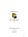
Weldarc Inverter Series
Operators Manual
Weldarc Manual Arc/TIG welders
Weldarc 125i – Model No. MC91-0, Iss A
Weldarc 145i – Model No. MC92-0, Iss A
Weldarc 165i – Model No. MC93-0, Iss A
05/07
WELDING INDUSTRIES OF AUSTRALIA
a division of Welding Industries Ltd
ABN 18 004 547 111
Telephone 1300 300 884
Facsimile 1300 301 884
Email: [email protected]
www.welding.com.au
MC91-40 Rev C
Weldarc 125i, 145i, 165i
Operators Manual
Contents
Section General Information
Model No. MC91-0, MC92-0, MC93-0 Iss A 05/07
Page
Safe Practices
3
1
Introduction
5
2
Receiving
5
3
Specifications
6
4
Power Source Controls
7
5
Operation
8
6
Installation
8
7
MMAW Welding
9
8
GTAW Welding
10
9
General Maintenance
11
10
Trouble Shooting
11
11
Service Information
12
12
Assembly and Parts Lists
14
13 Warranty information
16
Quality, Reliability, Performance
Weldarc 125i, 145i, 165i
Operators Manual
Read First
The information contained in this
manual is set out to enable you to
properly maintain your new equipment
and ensure that you obtain maximum
operating efficiency.
Please ensure that this information is
kept in a safe place for ready reference
when required at any future time.
When ordering spare parts, please quote
the model and serial number of the
power source and part number of the
item required. All relevant numbers are
shown in lists contained in this manual.
Failure to supply this information may
result in unnecessary delays in supplying
the correct parts.
Safety
Before this equipment is put into
operation, please read the Safe Practices
section of this manual. This will help to
avoid possible injury due to misuse or
improper welding applications.
Safe Practices When Using Welding
Equipment
These notes are provided in the interests
of improving operator safety. They should
be considered only as a basic guide to Safe
Working Habits. A full list of Standards
pertaining to industry is available from the
Standards Association of Australia, also various
State Electricity Authorities, Departments of
Labour and Industry or Mines Department
and other Local Health or Safety Inspection
Authorities may have additional requirements.
Australian Standard AS1674.2 provides a
comprehensive guide to safe practices in welding.
Eye Protection
NEVER LOOK AT AN ARC WITHOUT
PROTECTION. Wear a helmet with safety
goggles or glasses with side shields underneath,
with appropriate filter lenses protected by clear
cover lens. This is a MUST for welding, cutting,
and chipping to protect the eyes from radiant
energy and flying metal. Replace the cover lens
when broken, pitted, or spattered.
Recommended Shade Filter Lens
Plastic Handle on Welder
Please note that the handle fitted to the
Weldarc inverter is intended for carrying
the equipment by hand only.
DO NOT use this handle for suspending
or mounting the Weldarc in any other
manner.
Amps
TIG
MMAW
MIG
Pulsed
MIG
0-100
10
9
10
12-13
100-150
11
10
10
12-13
150-200
12
10-11
11-12
12-13
200-300
13
11
12-13
12-13
300-400
14
12
13
14
400-500
—
13
14
14
500 +
—
—
14
14
Burn Protection
The welding arc is intense and visibly bright. Its
radiation can damage eyes, penetrate lightweight clothing, reflect from light-coloured
surfaces, and burn the skin and eyes. Burns
resulting from gas-shielded arcs resemble acute
sunburn, but can be more severe and painful.
Wear protective clothing - leather or heat
resistant gloves, hat, and safety-toe boots.
Button shirt collar and pocket flaps, and wear
cuffless trousers to avoid entry of sparks and slag.
Avoid oily or greasy clothing. A spark may
ignite them. Hot metal such as electrode stubs
and work pieces should never be handled
without gloves.
Ear plugs should be worn when welding in
overhead positions or in a confined space.
A hard hat should be worn when others are
Quality, Reliability, Performance
Model No. MC91-0, MC92-0, MC93-0, Iss A 05/07
Weldarc 125i, 145i, 165i
working overhead.
Flammable hair preparations (hairspray) should
not be used by persons intending to weld or cut.
Toxic Fumes
Adequate ventilation with air is essential.
Severe discomfort, illness or death can result
from fumes, vapours, heat, or oxygen depletion
that welding or cutting may produce. NEVER
ventilate with oxygen.
Lead, cadmium, zinc, mercury, and beryllium
bearing and similar materials when welded or
cut may produce harmful concentrations of
toxic fumes. Adequate local exhaust ventilation
must be used, or each person in the area as
well as the operator must wear an air-supplied
respirator. For beryllium, both must be used.
Metals coated with or containing materials
that emit fumes should not be heated unless
coating is removed from the work surface, the
area is well ventilated, or the operator wears
an air-supplied respirator.
Work in a confined space only while it is being
ventilated and, if necessary, while wearing airsupplied respirator.
Vapours from chlorinated solvents can be
decomposed by the heat of the arc (or flame)
to form phosgene, a highly toxic gas, and lung
and eye irritating products. The ultra-violet
(radiant) energy of the arc can also decompose
trichlorethylene and perchlorethylene
vapours to form phosgene. Do not weld or
cut where solvent vapours can be drawn
into the welding or cutting atmosphere or
where the radiant energy can penetrate to
atmospheres containing even minute amounts
of trichlorethylene or percholorethylene.
Operators Manual
Walls touching combustibles on opposite sides
should not be welded on or cut. Walls, ceilings,
and floor near work should be protected by
heat-resistant covers or shields.
A person acting as Fire Watcher must be
standing by with suitable fire extinguishing
equipment during and for some time after
welding or cutting if;
• Combustibles (including building
construction) are within 10 metres.
• Combustibles are further than 10 metres but
can be ignited by sparks.
• Openings (concealed or visible) in floors
or walls within 10 metres may expose
combustibles to sparks.
• Combustibles adjacent to walls, ceilings,
roofs, or metal partitions can be ignited by
radiant or conducted heat.
After work is done, check that area is free of
sparks, glowing embers, and flames.
A tank or drum which has contained
combustibles can produce flammable vapours
when heated. Such a container must never
be welded on or cut, unless it has first been
cleaned as described in AS.1674-2. This includes
a thorough steam or caustic cleaning (or a
solvent or water washing, depending on the
combustible’s solubility), followed by purging and
inerting with nitrogen or carbon dioxide, and
using protective equipment as recommended
in AS.1674-2. Water-filling just below working
level may substitute for inerting.
Hollow castings or containers must be vented
before welding or cutting. They can explode.
Never weld or cut where the air may contain
flammable dust, gas, or liquid vapours.
Fire and Explosion Prevention
Shock Prevention
Be aware that flying sparks or falling slag can
pass through cracks, along pipes, through
windows or doors, and through wall or floor
openings, out of sight of the operator. Sparks
and slag can travel up to 10 metres from the arc.
Exposed conductors or other bare metal in the
welding circuit, or ungrounded electrically alive
equipment can fatally shock a person whose
body becomes a conductor. Ensure that the
equipment is correctly connected and earthed.
If unsure have the equipment installed by a
qualified electrician. On mobile or portable
equipment, regularly inspect condition of
trailing power leads and connecting plugs.
Repair or replace damaged leads.
Keep equipment clean and operable, free of
oil, grease, and (in electrical parts) of metallic
particles that can cause short circuits.
If combustibles are present in the work area, do
NOT weld or cut. Move the work if practicable,
to an area free of combustibles. Avoid
paint spray rooms, dip tanks, storage areas,
ventilators. If the work can not be moved,
move combustibles at least 10 metres away out
of reach of sparks and heat; or protect against
ignition with suitable and snug-fitting fireresistant covers or shields.
Model No. MC91-0, MC92-0, MC93-0 Iss A 05/07
Fully insulated electrode holders should be
used. Do not use holders with protruding
screws. Fully insulated lock-type connectors
should be used to join welding cable lengths.
Terminals and other exposed parts of electrical
units should have insulated knobs or covers
secured before operation.
Quality, Reliability, Performance
Weldarc 125i, 145i, 165i
Operators Manual
1 Introduction
2 Receiving
MMAW
Manual Metal Arc Welding (MMAW) is a process
where an arc is struck between a flux-coated
consumable electrode and the work piece. The
arc and the weld pool are both shielded by gases
generated by the flux coating of the electrode.
Check the equipment received against the
shipping invoice to make sure the shipment is
complete and undamaged. If any damage has
occurred in transit, please immediately notify
your supplier.
The Weldarc inverters have been designed to be
used with 2.0mm, 2.5mm and 3.2mm diameter
electrodes. The 165i can also use 4.0mm
electrodes. The smaller electrodes are used when
welding at lower currents, such as sheet metal
applications. Increasing the electrode diameter
permits higher welding currents to be selected.
WIA manufactures a wide range of mild steel and
special purpose electrodes which cater for home
workshop, rural, and industrial requirements. Some
popular AUSTARC electrodes are listed below. The
correctly selected AUSTARC electrode will influence
the quality of the weld, and the stability of the arc.
The Weldarc inverter package contains;
• Weldarc Inverter Power Source
• Arc Welding Lead Kit - 3 metre
• (This) Operating Manual MC91-40.
Optionally available
• TIG Torch Complete DB17V12R-DIN
150 Amp Miller Diamond-back TIG torch
with valve, complete with twist-lock
connection and fitted with 2.4mm collet
and thoriated tungsten
• Argon flow gauge regulator HA801AR
Austarc 12P, Classification E4112.
A popular general purpose electrode used with
ease in all positions, vertical up or down. The
smooth forceful arc makes it an ideal electrode
for all general mild steel applications.
Austarc 13S, Classification E4113.
A smooth running electrode with a soft arc,
particularly suited to light sheetmetal and
smooth mitre fillet welds.
Austarc 16TC, Classification E4816.
A low hydrogen electrode with good arc stability
and out-of-position welding characteristics. This
electrode is ideal for medium carbon steels, or
steels of unknown analysis.
Weldwell 31A, Classification E4111
A high cellulose electrode for all positional
welding, AC or DC. Particularly suited for vertical
and incline pipe welding where complete root
penetration is required.
Unicord
A high tensile (50tsi), chromium nickel electrode
specially formulated for joining all alloy steels and
irons, and for tool and die maintenance.
GTAW
Gas Tungsten Arc Welding (GTAW) is a welding
process where the arc is struck between a nonconsumable tungsten electrode and the work
piece. A ceramic nozzle surrounds the tungsten
electrode and directs a flow of inert gas, usually
Argon, over the electrode and the weld zone.
If filler metal is required, it is hand fed into the
welding arc. The DC current output of the Weldarc
inverter is suitable for welding most ferrous and
non-ferrous metals, but is not suitable for welding
Aluminium for which an AC machine is required.
Quality, Reliability, Performance
Model No. MC91-0, MC92-0, MC93-0, Iss A 05/07
Weldarc 125i, 145i, 165i
Operators Manual
3 Specifications
Power Source
Manufactured to Australian Standard AS1966.1.
Rated to ISO 60974-1.
125i
145i
165i
Primary Voltage
240 Vac +/- 10%,
50/60 Hz
240 Vac +/- 10%,
50/60 Hz
240 Vac +/- 10%,
50/60 Hz
Effective Primary Current
10 Amps
16.5 Amps
20.5 Amps
Maximum Primary Current
24.5 Amps
28 Amps
32.5 Amps
145 Amp, 25.8 V,
35% duty
165 Amp, 26.5 V,
40% duty
125 Amp, 25.0 V,
Maximum Rated Output @ 40oC
Duty cycle based on 10min cycle time 20% duty
Continuous Rated Output @ 40oC
55 Amp
85 Amp
110 Amp
Welding Current
5-125 Amps
5-145 Amps
5-165 Amps
Open Circuit Voltage –
VRD SAFE condition
10 V
10 V
10 V
Pulse TIG Frequency
1.5 Hz
1.5 Hz
Vary 0.5-100 Hz
Pulse TIG Width
50%
50%
Vary 10-90%
Mass
7.1 kg
7.1 kg
7.1 kg
Supply Plug
10 Amp
15 Amp
15 Amp - for
commissioning only
Fitted Supply Cable
1.5mm2 Three Core, 1.5mm2 Three Core, 2.5mm2 Three Core,
Heavy Duty PVC
Heavy Duty PVC
Heavy Duty PVC
Power Supply Outlet (240 V) &
Extension Lead Rating
10 Amp
15 Amp
20 Amp
Power Supply Circuit Breaker
Rating
20 Amps
25 Amps
25 Amps
Cooling
Fan cooled, air drawn in through front grille.
Note: The Weldarc 165i is fitted with a 15 Amp
plug for commissioning purposes, and should
only be operated to 145i rating. If the
equipment is to be used at maximum output
current and duty cycle, an appropriate 20 Amp
plug should be fitted by a qualified electrician.
Model No. MC91-0, MC92-0, MC93-0 Iss A 05/07
IMPORTANT NOTICE: Warranty may be
voided if equipment is powered from an
unsuitable engine driven generator.
Generators used to power this equipment
must have a minimum capacity of 6 kW
continuous and incorporate output voltage
regulation. Generators without voltage
regulation must have a minimum capacity of
16 kW.
Quality, Reliability, Performance
Weldarc 125i, 145i, 165i
Operators Manual
4 Power Source Controls
2
Power Switch
Located on the rear panel
3
10
4
1
5
6
7
8
9
Fig 1 Power Source Controls
1 Current Control
6 TIG Mode & Pulse TIG Mode
This control sets the output current level of
the power source within the available range.
Rotate the knob clockwise to increase the
output current.
This light is on when TIG (Gas Tungsten Arc
Welding) mode is selected.
2 Over Temperature Indicator
This light is on if any internal thermal
protection devices have operated.
3 VRD Safe Mode Indicator
This light is flashing when pulse TIG (Pulse Gas
Tungsten Arc Welding) mode is selected.
7 Weld Mode
There are four weld modes available.
Press this button to step between Stick,
Cellulose, tig & Pulse tig mode.
This light is on when the voltage across the
output terminals is reduced to a safe level.
8 Duty Cycle
4 Stick Mode
If Pulse TIG mode is selected, this knob varies
the pulse width from 10% to 90%. This feature
only available on the 165i.
This light is on when Stick Mode (Manual Metal
Arc Welding) is selected. This mode is used for
all mmaw stick electrode process, except for
Cellulose type electrodes.
5 Cellulose Stick Mode
This light is on when Cellulose is selected, and is
used for running Cellulose type electrodes.
9 Frequency Control
If Pulse TIG mode is selected, this knob varies
the frequency of the pulses from 0.5 Hz to
100 Hz (ie 0.5 to 100 pulses per second). This
feature only available on the 165i.
10Power On/Off Switch
In the OFF position, this switch isolates the
power source from the mains power supply.
Quality, Reliability, Performance
Model No. MC91-0, MC92-0, MC93-0, Iss A 05/07
Weldarc 125i, 145i, 165i
Operators Manual
5 Operation
6 Installation
VRD Function
Connection to Electrical Mains Power
Supply
Whenever the welding output of the Weldarc
inverter is open circuit (ie not arcing), the
voltage across the welding leads is reduced
to a safe level. This provides an increased
level of safety to the welding operator during
operations such as changing the electrode. The
green coloured “VRD SAFE” indicator on the
front panel is on to confirm the output is in the
safe condition.
The term VRD refers to a “Voltage Reducing
Device”. The Weldarc inverter incorporates
Smartstart VRD Technology®. This feature
provides the safety associated with VRD
combined with excellent arc starting
characteristics. Smartstart VRD Technology®
complies with AS1674.2 for Category “C”
conditions.
Sleep Mode
The Weldarc inverter goes into “sleep mode”
after 10 minutes of not welding. This is a low
power consumption mode which includes
shutting down the fan.
As soon as the operator attempts to strike an
arc or if any button is pressed, the Weldarc
inverter automatically “wakes up” in the mode
in which it was last used.
Shoulder Strap
To attach the shoulder strap to the Weldarc,
feed the strap through the top of the shoulder
strap bracket located on top of the Weldarc at
the front and rear.
The Weldarc 145i and 165i are fitted with a 15
Amp plug and socket, recognisable by a wide
Earth pin. Power Supply authorities require
that equipment fitted with a 15 Amp plug shall
ONLY be connected to a 240 Volt,
15 Amp power point. DO NOT modify the plug.
Note: The Weldarc 165i is fitted with a 15 Amp
plug for commissioning purposes, and should
only be operated to 145i rating. If the
equipment is to be used at maximum output
current and duty cycle, an appropriate 20 Amp
plug should be fitted.
The Weldarc 125i is fitted with a 10 Amp plug.
The minimum capacity of the main power
supply wiring and power outlet supplying a
welder is selected according to the Effective
Primary Current of the equipment. Refer to
Section 3.
The minimum recommended main power
supply circuit breaker ratings for Weldarc
inverters are listed in Section 3.
The current rating of the mains cable depends
on cable size and method of installation. Refer
to AS/NZS 3008.1, Table 9.
If it becomes necessary to replace the mains
flexible supply cable, use only cable with
correct current rating. See Section 3.
If it is necessary to use an extension power
supply cable, ensure that it is rated as per
Section 3. Voltage drop which will occur over
long lengths of cable will reduce the quality
of welds and the maximum welding current
available from the equipment.
As noted previously, it is not recommended that
the Weldarc inverter be powered from small
engine-driven generator sets unless they have
adequate voltage regulation. Poor regulation
results in peaks of supply voltage which can
occur with some equipment of this type.
Excessive voltage peaks can damage the circuits
of the welder.
Fig 2 Attaching the Weldarc Shoulder Strap
Model No. MC91-0, MC92-0, MC93-0 Iss A 05/07
Quality, Reliability, Performance
Weldarc 125i, 145i, 165i
Operators Manual
7 MMAW Welding
To strike the arc, drag the end of the electrode
along the work piece as if striking a match.
As the arc initiates, lift the electrode slightly
away, aiming to establish an arc length of
approximately 3mm.
There are two Modes for MMAW :
• Normal stick electrode
• Cellulose stick electrode
Connection for Mmaw Welding
It is important to select the electrode polarity
in accordance with the manufacturers
recommendations for that electrode. Most
common electrodes, including cellulose types,
are operated with the electrode at positive
polarity, as illustrated in Figure 2.
As the electrode end is consumed, feed the
electrode into the arc in order to maintain
arc length. As a general rule, the arc should
be held as short as possible while still giving
stable burn off and good weld appearance. An
arc which is too long cause an unwieldy flow
of metal with a rough weld appearance and
reduced penetration. An arc too short leads
to a narrow weld deposit and “stuttery” arc
characteristics, and the electrode is liable to
freeze onto the work piece.
As the solidified weld deposit forms, move the
end of the electrode slowly along the weld
path, aiming to maintain a pool of molten weld
metal behind the arc. Decreasing this rate of
travel will result in a wider weld deposit, and
similarly increasing it will narrow the weld
deposit.
Electrode holder
Always fill the crater which tends to form at the
end of a weld deposit, by pausing momentarily
before withdrawing the electrode to break the
arc. Unfilled craters are a point of weakness,
and can lead to weld cracking.
Work clamp
Fig 3 Connections for mmaw, Electrode Positive
Current Range for General Purpose
Electrodes
Diameter (mm)
Current (Amps)
2.0
40 -60
Mmaw Operation
2.5
60 - 85
Be certain that you are wearing suitable
protective clothing, gloves etc and that you are
working in a non-hazardous area. If necessary,
refer again to Section 1 - Safe Practices in this
manual.
3.2
90 - 130
4.0
130 - 180
Connect the work clamp to the work piece.
Place the desired electrode in the electrode
holder.
Turn on the power switch located on the rear
panel. Wait approximately 5 seconds as the unit
goes through its initiation sequence.
Press the Weld Mode button until the Stick or
Cellulose Mode light is on. The Weldarc inverter
keeps the last mode used in memory, so this
step is only necessary when using a different
mode to that used last.
Select an appropriate welding current for the
electrode diameter by setting the knob on the
machine front panel. WIA AUSTARC electrodes
will give the best results.
Quality, Reliability, Performance
Model No. MC91-0, MC92-0, MC93-0, Iss A 05/07
Weldarc 125i, 145i, 165i
Operators Manual
8 GTAW Welding
GTAW Operation
Connection for Gtaw Welding
For GTAW, the torch is connected negative
terminal. Figure 4 illustrates the correct
connection of the welding torch and gas
supply. Welding grade Argon is the shielding
gas most commonly used for DC GTAW
welding.
Before first use of the welding torch, allow
gas to purge the torch and hoses for 5 minutes
at approximately 10 litres/min. For welding
purposes, the gas flow rate should be set in the
range 2 - 5 litres/min.
Tungsten electrodes for DC GTAW should be
1 - 2% Thoriated or Witstar. This type will
provide the best arc initiation, arc stability and
tip shape retention characteristics. Thoriated
electrodes can be recognised by a red coded
end. The tungsten electrode is ground to
a point, with the grinding marks pointing
towards the tip. For welding currents less than
20 amps, the included angle of the point should
be 30o, for currents greater than 20 amps, the
recommended angle is 60o. When set in the
torch, the tungsten should protrude 6mm from
the ceramic gas nozzle.
Connect the Work Clamp to the work piece.
Turn on the power switch located on the rear
panel. Wait approximately 5 seconds as the unit
goes through its initiation sequence.
Press the Weld Mode button until the TIG
Mode light is on. The Weldarc inverter keeps
the last mode used in memory, so this step is
only necessary when using a different mode to
that used last.
Select an appropriate welding current for the
job by setting the knob on the machine front
panel.
To initiate the arc, lightly touch the tungsten
electrode onto the work piece, then smoothly
lift it away to establish an arc length slightly
longer than the diameter of the electrode.
Use of a copper striking plate can be used to
avoid electrode contamination. The electrode
can also be contaminated by contact with the
filler rod. A contaminated electrode produces
an unstable arc. if this occurs regrind the
electrode tip.
Pulse GTAW Operation
Set for 2-5 litres/min
To select Pulse TIG Mode, press the Weld
Mode button until the Pulse TIG Mode light
is flashing. The Weldarc inverter keeps the
last mode used in memory, so this step is only
necessary when using a different mode to that
last used.
To TIG Torch
When Pulse TIG Mode is used, the welding
current is generated in a series of pulses. This
pulsing action controls the heat input to the
material, while still providing a high enough
current to achieve weld penetration.For 125i
and 145i the pulse timing is fixed.
Welding grade
Argon
To work clamp
Fig 4 Cable and Hose Connections for Gtaw
For 165i both the frequency and duration of
the welding current pulses may be varied. The
frequency control knob sets the pulses per
second. A low frequency setting can be used to
assist the operator to produce a uniform weld
when the hand fed filler rod is advanced in
time with each pulse. High frequency settings
tend to make the arc more directional, and may
assist in producing a small fillet weld in thin
materials.
For 165i the Pulse % control knob sets the
percentage of pulse time in each cycle. Higher
settings produce a hotter weld.
Select an appropriate pulse peak current for
the job by setting the knob on the machine
front panel.
Initiate the arc in the same manner as that
described above.
10 Model No. MC91-0, MC92-0, MC93-0 Iss A 05/07
Quality, Reliability, Performance
Weldarc 125i, 145i, 165i
Operators Manual
9 General Maintenance
Before removing the power source
covers, ENSURE that the equipment is
disconnected from the mains power supply.
When the equipment is energised LETHAL
VOLTAGES are present on the electrical
components enclosed.
10 External Trouble Shooting
If the following checks do not identify the
fault condition, the equipment should be
returned to a WIA Service agent. Phone
1300 300 884 for details of your nearest
service agent.
No Welding Current
The Weldarc inverter turns the cooling fan off
when it is not required to reduce dust intake.
However care should be taken to prevent
excessive dust and dirt entering the welding
power source. It is recommended that at
regular intervals, according to the prevailing
conditions, the machine covers be removed and
any accumulated dust be removed by the use of
dry, low pressure compressed air.
Check:
1 Check that mains supply is available at the
Weldarc inverter power source. At least
one of the key pad lights should be on.
If not, test outlet using a known working
appliance.
2 Check that the welding and work leads are
connected securely to the output sockets at
the front of the machine.
3 Check for continuity of the work lead,
work clamp and electrode holder. Loose
connections can prevent proper flow of the
welding current.
4 The Weldarc inverter welding power source
incorporates an in built protection device
which will trip if the unit is overloaded.
In this event, the machine will not deliver
welding current, and the red Over Temp
light will be on. If the thermal overload
protection device has been tripped, leave
the machine energised with the fan running
to achieve the maximum cooling rate.
Quality, Reliability, Performance
Model No. MC91-0, MC92-0, MC93-0, Iss A 05/07
11
Weldarc 125i, 145i, 165i
Operators Manual
11 Service Information.
CAUTION: The following information is
intended for use by qualified service
personnel. When the equipment is
energised, Lethal Voltages are
present on the electrical and electronic
components. It is not intended that persons
without suitable training and knowledge
attempt to perform service tasks on the
components of this welder.
The electrical components of the equipment
are shown in the circuit diagram below. The
Weldarc inverter is an inverter type design,
where the mains supply is first rectified, filtered
then chopped to a high frequency before being
applied to the welding transformer. The output
of this transformer is rectified to form the
welding output of the machine.
12 Model No. MC91-0, MC92-0, MC93-0 Iss A 05/07
Quality, Reliability, Performance
Weldarc 125i, 145i, 165i
Operators Manual
11.1 Circuit Diagrams - Power Source
Fig 5 Power Source Circuit Diagram
Quality, Reliability, Performance
Model No. MC91-0, MC92-0, MC93-0, Iss A 05/07
13
Weldarc 125i, 145i, 165i
Operators Manual
12 Assembly and Parts List - Weldarc Inverter
4
3
5
6
165i only
7
7
8
2
9
1
23
10
22
11
21
12
13
20
14
15
16
8
17
9
18
19
Fig 6 Weldmatic Inverter Power Source Assembly
14 Model No. MC91-0, MC92-0, MC93-0 Iss A 05/07
Quality, Reliability, Performance
Weldarc 125i, 145i, 165i
Operators Manual
Item #
Part #
Description
Qty
1
M0022
Foot
4
2
PST009
Panel Set
1
3
MZ208015
Handle Assembly
1
4
M0024
Strap Support
2
5
MC100-54
Knob (large)
1
6
E0016
Knob (small)
2
7
LST014
LST015
LST016
Label Set 125i
Label Set 145i
Label Set 165i
1
1
1
8
SA140-0/2
Socket Dinsel 25mm
2
9
M0023
Grill Moulding
1
10
E0023
Switch DPDT Panel Mount
1
11
MC102-30
MC100-30
MC101-30
125i Flex 10 Amp + Plug 10 Amp
145i Flex 15 Amp + Plug 15 Amp
165i Flex 20 Amp + Plug 15 Amp
1
1
1
12
CP101-0/17
Fan Finger Guard 120mm
1
13
MC100-38
Fan
1
14
MC100-41
Transformer Spring Clip
1
15
L0008
Planar T/F 4.2 kW
1
16
D0018
Rectifier 1ph 50 Amp 600 V
2
17
R0015
Thermistor
1
18
D0019
Mosfet 55 Amp 500 V
4
19
D0017
UFR Diode 100 Amp 200 V
1
20
PWA002
Voltage Boost Circuit
1
21
MC102-11N
MC100-11N
MC101-11N
125i PCB Assembly Logic Control
145i PCB Assembly Logic Control
165i PCB Assembly Logic Control
1
1
1
22
M0021
Shoulder Strap
1
23
PWA003
PWA004
125i & 145i PCB Assembly Power Control
165i PCB Assembly Power Control
1
1
Not shown
AA58-1/3
MMAW Weld Lead 3m
1
Not shown
AA58-2/3
Work Lead 3m
1
Quality, Reliability, Performance
Model No. MC91-0, MC92-0, MC93-0, Iss A 05/07
15
Weldarc 125i, 145i, 165i
13 Warranty Information
WIA Gold Shield 3 Year Warranty
Effective 1st March 2005
At WIA, we are serious about product quality.
Every new Weldmatic and Weldarc machine
comes fully backed by the WIA ‘Gold
Shield 3 Year Warranty’, covering parts and
workmanship, so you can be guaranteed
you’re buying reliability and performance.
This limited warranty supersedes all previous
WIA (Welding Industries of Australia)
warranties and is exclusive with no other
guarantees or warranties expressed or implied.
Limited Warranty
Subject to the terms and conditions below, WIA
warrants to its original retail purchaser that new
WIA equipment sold after the effective date of
this limited warranty is free of defects in material
and workmanship at the time it is shipped by WIA.
THIS WARRANTY IS EXPRESSLY IN LIEU OF
ALL OTHER WARRANTIES, EXPRESS OR
IMPLIED, INCLUDING THE WARRANTIES OF
MERCHANTABILITY AND FITNESS.
Within the warranty periods listed below, WIA
will repair or replace any warranted parts or
components that fail due to such defects in
material or workmanship. WIA must be notified
in writing within thirty (30) days of such defect
or failure, at which time WIA will provide
instructions on the warranty claim procedures
to be followed.
WIA shall honour warranty claims on warranted
equipment in the event of such a failure within
the warranty time periods. All warranty time
periods start on the date that the equipment
was delivered to the original retail purchaser,
or 18 months after the equipment date of
manufacture, whichever is the earlier.
Parts and workmanship on Weldarc and
Weldmatic equipment are covered for a period
of 3 years (except for gas regulator, gun cable
and consumables listed below.)
Items replaced under original warranty are
warranted for the remainder of the original
equipment warranty, or for a period of ninety
(90) days, whichever is the greater.
Operators Manual
WIA’s Limited Warranty shall not apply to:
1 Consumable components; such as contact
tips, cutting nozzles, contactors, brushes,
relays or parts that fail due to normal wear.
2 Equipment that has been modified by any
party other than WIA, or equipment that
has been improperly installed, improperly
operated or misused based upon industry
standards, or equipment which has not had
reasonable and necessary maintenance,
or equipment which has been used for
operation outside of the specifications for
the equipment.
WIA PRODUCTS ARE INTENDED FOR PURCHASE
AND USE BY COMMERCIAL / INDUSTRIAL USERS
AND PERSONS TRAINED AND EXPERIENCED
IN THE USE AND MAINTENANCE OF WELDING
EQUIPMENT.
In the event of a warranty claim covered by
this warranty, the exclusive remedies shall be,
at WIA’s option: (1) repair; or (2) replacement;
or, where authorised in writing by WIA in
appropriate cases, (3) the reasonable cost of
repair or replacement by an authorised WIA
service agent; or (4) payment of or credit for
the purchase price (less reasonable depreciation
based upon actual use) upon return of the
goods at customer’s risk and expense.
WIA’s option of repair or replacement will
be F. O. B. Factory at Melrose Park, Adelaide,
or F. O. B. at a WIA authorised service
facility as determined by WIA. Therefore
no compensation or reimbursement for
transportation costs of any kind will be
allowed.
TO THE EXTENT PERMITTED BY LAW, THE
REMEDIES PROVIDED HEREIN ARE THE SOLE
AND EXCLUSIVE REMEDIES. IN NO EVENT SHALL
WIA BE LIABLE FOR DIRECT, INDIRECT, SPECIAL,
INCIDENTAL OR CONSEQUENTIAL DAMAGES
(INCLUDING LOSS OF PROFIT), WHETHER BASED
ON CONTRACT, TORT OR ANY OTHER LEGAL
THEORY.
ANY EXPRESS WARRANTY NOT PROVIDED
HEREIN AND ANY IMPLIED WARRANTY,
GUARANTEE OR REPRESENTATION AS TO
PERFORMANCE, AND ANY REMEDY FOR
BREACH OF CONTRACT TORT OR ANY OTHER
LEGAL THEORY WHICH, BUT FOR THIS
PROVISION, MIGHT ARISE BY IMPLICATION,
OPERATION OF LAW, CUSTOM OF TRADE OR
COURSE OF DEALING, INCLUDING ANY IMPLIED
WARRANTY OF MERCHANTABILITY OR FITNESS
FOR PARTICULAR PURPOSE, WITH RESPECT TO
ANY AND ALL EQUIPMENT FURNISHED BY WIA
IS EXCLUDED AND DISCLAIMED BY WIA.
Gas regulator and gun/cable assembly are
warranted for 90 days.
16 Model No. MC91-0, MC92-0, MC93-0 Iss A 05/07
Quality, Reliability, Performance