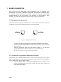
1
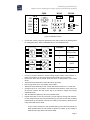
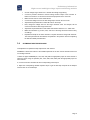
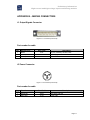
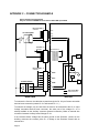
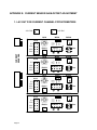
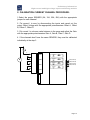
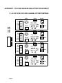
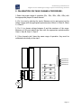
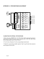
Preliminary Information High-current and high-voltage input conditioning module CH A C25A Cap W12A RV12A Offset 600V Gain SIG calibration W13A 400V RV11A GND -2.5V 100V 200V +2.5V measure 50V 5 Filter 7 S13A Figure 6: Calibration section Choose filter value by setting the appropriate rotary switch. Refer to the drawing below for existing filter values. Refer to APPENDIX D for a more detailed location. 5 5 2 1 7 1 OFF (no filter) 2 200 HZ 3 2 KHZ 4 20 KHZ 5 4 7 Filter 7 5 3 Position 7 Connect a precision voltmeter to the first voltage channel output of the connector J1. Refer to the section 2.3.2 to know the channel output position on the connector. Remove the shunt from the header W12A and put it on GND position of the header W13A. Adjust RV12A potentiometer to read 0.000 volts on the output. Next, change the shunt to +2.5V position of the header. Adjust RV11A potentiometer to read –10.000 volts with the tolerance of +/- 0.005 volts. Change the shunt to –2.5V position. The voltmeter should show the same value as for the previous measure but with reverse sign if the reference voltage was properly adjusted precisely. After the calibration replace the shunt on the header W12A. Repeat these steps for the other channels. The part reference change with channels. For the voltage channels, the Gain potentiometers go from RV11A to RV11D, the Offset potentiometers go from RV12A to RV12D, the header go from W13A to W13D and the rotary switch from S13A to S13D. For the current channels, the Gain potentiometers go from RV51A to RV51D, the Offset potentiometers go from RV52A to RV52D, the header go from W53A to W53D and the rotary switch from S53A to S53D. Page 7