1
FCC Warning
This equipment has been tested and found to comply with the limits for a Class A digital
device, pursuant to Part 15 of the FCC Rules. These limitations are designed to provide
reasonable protection against harmful interference in a residential installation. This
equipment generates, uses and can radiate radio frequency energy and, if no installed
and used in accordance with the instructions, may cause harmful interference to radio
communications. However, there is no guarantee that interference will not occur in a
particular installation. If this equipment does cause harmful interference to radio or
television reception, which can be determined by turning the equipment off and on, the
user is encouraged to try to correct the interference by one or more of the following
measures:
!" Reorient or relocate the receiving antenna.
!" Increase the separation between the equipment and receiver.
!" Connect the equipment into a different outlet from that the receiver is connected.
!" Consult your local distributors or an experienced radio/TV technician for help.
!" Shielded interface cables must be used in order to comply with emission limits.
Changes or modifications to the equipment, which are not approved by the party
responsible for compliance could affect the user’s authority to operate the equipment.
Copyright © 1999 All Rights Reserved.
Company has an on-going policy of upgrading its products and it may be possible that
information in this document is not up-to-date. Please check with your local distributors
for the latest information. No part of this document can be copied or reproduced in any
form without written consent from the company.
Trademarks:
All trade names and trademarks are the properties of their respective companies.
Table of Contents
1. Unpacking Information
2. Introduction To SWH-2024D NWay Switching Hub
2.1
2.2
2.3
2.3.1
2.3.1.1
2.3.1.2
2.3.1.3
2.3.1.4
2.3.2
2.3.2.1
2.3.2.2
2.3.3
2.3.4
2.3.5
2.4
2.4.1
2.4.2
General Description
Key Features
The Front Panel
System LEDs
Power LED
Module/Fiber Link LED
VLAN/Port Trunk LEDs
Slide-in module LEDs
Port LEDs
Link/Act LED
FDX/COL LED
Uplink Port
VLAN/Trunk Mode Button
Reset Button
The Rear Panel
Power Connecting
Console Port
3. Installing And Using SWH-2024D NWay Switching Hub
3.1
3.1.1
3.1.2
3.1.3
3.1.3.1
3.1.3.2
3.1.3.3
Installing The SWH-2024D NWay Switching Hub
Desktop Installation
Rack-Mount Installation
Installing Network Cables
Station Connection with Twisted-Pair Cable
Switch to Switch Connections with Twisted-Pair Cable
Network Application
4. Switching Operation
4.1
4.2
4.3
MAC Address Table & Learning
Filtering and Forwarding
Store and Forward
5. Console Program
6. Product Specifications
1. Unpacking Information
Thank you for purchasing the SWH-2024D NWay switching hub. Before you start,
please check all the contents of this package.
The product package should include the following:
1.
One SWH-2024D NWay switching hub
2.
One power cord
3. Screws and rubber foot
4. Null modem adapter
5. Rack-mount brackets
6. User’s guide
2. Introduction To SWH-2024D NWay Switching Hub
2.1
General Description
The device is a powerful, high-performance Fast Ethernet switching hub, with all 24
ports capable of 10 or 100Mbps auto-negotiation operation (NWay) which means the
switch could automatically negotiate with the connected partners on the network speed
and duplex mode. It is ideal for micro-segmenting large networks into smaller, connected
subnets for improved performance, enabling the bandwidth demanding multimedia and
imaging applications. Moreover, the 10/100Mbps auto-sensing ability provides an easy
way to migrate 10Mbps to 100Mbps networks with no pain. Compared to the shared
10Mbps or 100Mbps networks, the switching hub delivers a dedicated 10/100Mbps
connection to every attached client with no bandwidth congestion issue.
The switching hub also supports more value-added function include port trunk and
virtual LAN. Port trunk function could be used to build up a fat pipe up to 800Mbps
between switches that will solve the bandwidth bottleneck on backbone connection.
Virtual LAN provides system security function which keep the resources only could be
shared in the same virtual group and all the other nodes did not belong to the group can
not access the resources.
Store-and-forward switching mode promises the low latency plus eliminates all the
network errors, including runt and CRC error packets. To work under full-duplex mode,
transmission and reception of the frames can occur simultaneously without causing
collisions as well as double the network bandwidth.
The switching hub is plug-n-play without any software to configure and also fully
compliant with all kinds of network protocols. Moreover, the rich diagnostic LEDs on the
front-panel for providing the operating status of individual port and whole system.
For network connection:
The switching hub can use the following types of cabling:
!" 10BASE-T Category 3, 4 or 5 UTP/STP
!" 100BASE-TX Category 5 UTP/STP
Category 5 cable is preferred to be using with this product in structured
wiring environments. This will ensure correct operation of all ports at 10Mbps or
100Mbps.
2.2
Key Features
The switching hub provides the following key features:
!" Complies with 10BASE-T specifications of the IEEE802.3 standard
!" Complies with 100BASE-TX specifications of the IEEE802.3u standard
!" Twenty-four RJ-45 ports for 100Base-TX and 10Base-T connectivity
!" Supports NWay protocol for speed (10/100Mbps) and duplex mode (Half/Full)
auto-detection
!" One uplink port for cascading switch to switch or switch to hub with no cross-over
cable
!" Supports full and half duplex operation on all ports
!" Supports one mode button for reviewing the port trunk and VLAN configuration
!" Supports one system reset button
!" Optional slide-in module support 100BASE-FX connection
(The slide-in module is an alternative port to port 12 which means both ports can
not work at the same time)
!" Wire-speed packet filtering and forwarding rate
!" Store-and-forward architecture filters fragment & CRC error packets
!" Supports 1K MAC address entries in whole system
!" 3MBytes buffer memory
!" Supports extensive LED indicators for network diagnostics
!" Internal universal switching power supply (100 ~ 240VAC)
!" FCC Class A, CE
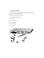
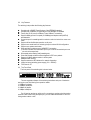
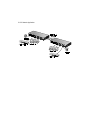
2.3 The Front Panel
The front panel of the switching hub is shown below.
The auto-negotiation feature of the switching hub allows each port of the device
running at one of the following four operation modes:
1. 100Mbps full-duplex
2. 100Mbps half-duplex
3. 10Mbps full-duplex
4. 10Mbps half-duplex
Port 24 can be used as an uplink port for connecting to another unit without using
crossover cable. When using the uplink port, you can extend the distance to 100m for
linking another switch or hub.
2.3.1
System LEDs
System LED indicators are located on the front panel for showing the operating
status of the whole device.
2.3.1.1 Power LED
This indicator lights green when the hub is receiving power; otherwise, it is off.
2.3.1.2 Module/Fiber Link LED
When the fiber optional module slide into the system then the module LED will be
green. The fiber link LED shows the link status of the optional module.
2.3.1.3 VLAN/Port Trunk LEDs
When the VLAN LED is light, the group LEDs (A~F) represent the VLAN groups. If
the Trunk LED is light then the group LEDs (A~F) mean the trunk groups. For example:
when the VLAN group A is selected, the VLAN LED, group A LED and the link/act LED of
the ports in the VLAN group A will light. Same situation for port trunk.
2.3.1.4 Slide-in module LEDs
The slide-in module support 100BASE-FX media connection and with two
diagnostic LEDs with the following definition:
LED
Link/Act
FDX/COL
Operation
Link is present (Green), Activity (Blinking Green)
Full-Duplex (Amber), Half-Duplex (Off), COL (Blinking Amber)
2.3.2 Port LEDs
Port LED indicators are located on the front panel for showing the operating status
of each port.
2.3.2.1 Link/Act LED
Every port has a Link/Activity LED. Steady light (link state) indicated that the port
has good linkage to its associated device. Flashing indicates there is traffic transverses
the port. The following is table for LED definition.
Link/Activity LED
Off
Green
Flashing Green
Amber
Flashing Amber
Status
No Connection
Connected as 100Mbps
There is traffic transverses the port
Connected as 10Mbps
There is traffic transverses the port
If the port is connected but the Link/Activity LED is dark, check the following items:
1. The switching hub and the connected device’s power are on or not
2. The port’s cable is firmly seated in its connectors in the switching hub and in the
associated device.
3. The connecting cable is good and with correct type
4. The connecting device, including any network adapter is functioning.
2.3.2.2 FDX/COL LED
A collision occurs when two stations within a collision domain attempt to transmit
data at the same time. Intermittent flashing amber of the collision LED is normal; the
contending adapters resolve each collision by means of a wait-then-retransmit algorithm.
Frequency of collisions is an indicator of heavy traffic on the network.
If the FDX/COL light amber which means the port is under full-duplex operation or
dark for half-duplex mode.
2.3.3
Uplink Port
The uplink port is an alternative port to port 24 and user could use this port for
switch to hub or switch to switch connection without cross-over cable.
2.3.4
VLAN/TRUNK mode button
Push this button continuously will show the configuration of VLAN and Trunk groups.
The sequence of displaying will be
VLAN-A -> VLAN-B -> VLAN-C -> VLAN-D -> VLAN-E -> VLAN-F then
Trunk-A -> Trunk-B -> Trunk-C -> Trunk-D -> Trunk-E -> Trunk-F
When you select any VLAN or Trunk group, the related ports belong to that group
will have the link/act LED steady green. The status display will stay 2~3 seconds and all
the LEDs will work normally after that.
2.3.5
Reset button
Press the reset button will reboot the whole system.
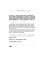
2.4
The Rear Panel
The rear panel of the hub is shown below
2.4.1
Power Connecting
For compatibility with electric service in most areas of the world, the switching hub’s
power supply automatically adjusts to line power in the range 100~240 VAC and 50~60
Hz.
Plug the female end of the power cord firmly into the receptacle on the rear panel of
the switching hub. Plug the other end of the power cord into an electric service outlet then
the power will be ready.
2.4.2
Console Port
Through the console port, it provides rich diagnostic information includes network
statistics, link status and system setting. The operating mode of the console port is:
DTE (terminal mode)
9600 (baud rate)
n (non-stop bit)
8 (8 data bits)
1 (1 parity bit)
You could use a normal RS-232 cable connect to the null modem then plug into the
console port on the device. After the connection, you could run any terminal emulation
program (Winterm, Telix, … and so on) to enter the startup screen of the device. All the
detail software operation, please refer to “Console Program” session.
3. Installing And Using SWH-2024D NWay Switching Hub
3.1
Installing The SWH-2024D NWay Switching Hub
The hub does not require software configuration. Users can immediately use any of
the features of this product simply by attaching the cables and turning the power on.
3.1.1 Desktop Installation
To locate the switching hub on the desktop and place the hub on a clean, flat desk
or table close to a power outlet. Plug in all network connections and the power cord, then
the system is ready.
When deciding where to put the switching hub then you must ensure:
!" It is accessible and cables can be connected easily
!" Cabling is away from:
Sources of electrical noise such as radios, transmitters and broadband amplifiers
Power lines and fluorescent lighting fixtures.
!" Water or moisture can not enter the unit
!" Air flow around the unit and through the vents in the side of the case is not
restricted (company recommend that you provide a minimum of 25mm inch
clearance)
To prolong the operational life of your units:
!" Never stack units more than eight high if freestanding.
!" Do not place objects on top of any unit or stack
!" Do not obstruct any vents at the sides of the case
3.1.2 Rack-Mount Installation (only for 19 inch product)
The switching hub may standalone, or may be mounted in a standard 19-inch
equipment rack. Rack mounting produces an orderly installation when you have a
number of related network devices. The switching hub is supplied with two mounting
brackets and screws. These are used for rack mounting the unit.
Rack Mounting the Switching Hub
The switching hub should be able to fit in the 19 inch rack.
1. Disconnect all cables from the switching hub before continuing.
2. Place the unit the right way up on a hard, flat surface with the front facing toward you.
3. Locate a mounting bracket over the mounting holes on one side of the unit.
4. Insert the screws and fully tighten with a suitable screwdriver.
5. Repeat the two previous steps for the other side of the unit.
6. Insert the unit into the 19" rack and secure with suitable screws (not provided).
7. Reconnect all cables.
3.1.3 Installing Network Cables
After placing the hub on the desktop, then we need to know how to connect the
device to network.
3.1.3.1 Station Connections with Twisted-Pair Cable
Connect each station to the hub by a twisted-pair straight cable (10BASE-T or
100BASE-T cables). Plug one RJ-45 connector into a front-panel port of the hub, and
plug the other RJ-45 connector into the station’s network adapter.
3.1.3.2 Switch to Switch Connections with Twisted-Pair Cable
In making a switch to switch connection, you could use uplink port to connect
another switch with no crossover cable. The uplink connector is wired to the same
conductors as the port 24 connector, but with certain pin positions interchanged to
provide a crossover, and thus allow using a straight cable to make a switch to switch
connection.
Keep in mind that the uplink connector is not an independent port. It is only an
alternative connector to port 24 for switch to switch cabling. Port 24 is fully occupied
whenever
1.
A switch to switch connection is made through its uplink connector, or
2.
Any kind of connection is made directly through the port 24 connector.
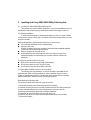
3.1.3.3 Network Application
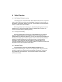
4. Switch Operation
4.1
MAC Address Table and Learning
The switching hub is implemented with a MAC address table which is composed of
many entries. Each entry is used to store the address information of network nodes on
the network, including MAC address, port ID, etc. The information is the most important
base to do packet filtering and forwarding.
When one packet comes in from any port, the switching hub will learn the source
address, port ID, and the other related information in address table. Therefore, the
content of the MAC table will update dynamically.
4.2
Filtering and Forwarding
When one packet comes in from any port of the switching hub, it will check the
destination address besides the source address learning. The hub will look up the
address table for the destination address. If not found, this packet will be forwarded to all
the other ports except the port which this packet comes in. If found, and the destination
address is located at different port from this packet comes in, the packet will be
forwarded to the port where this destination address is located according to the
information of address table. But, if the destination address is located at the same port as
this packet comes in then this packet will be filtered.
4.3 Store and Forward
Store-and-forward is one kind of packet-forwarding methodology. As a
store-and-forward switching hub, it will store the complete packet in the internal buffer
and do the complete error checking before transmitting to the network. Therefore, no
error packets will disturb the network. It is the best choice when a network needs
efficiency and stability.
5. Console Program
The SWH-2024D Switch has an RS-232 console port for direct console management
Pin
1
2
3
4
5
6
7
8
9
Description
DCD (Data Carrier Detect)
RX (Receive)
TX (Transmit)
DTR (Data Terminal Ready)
GND (Ground)
DSR (Data Set Ready)
RTS (Request To Send)
CTS (Clear To Send)
N/A
(RS-232 DB-9, DTE/male connector)
When connecting a terminal directly to the switch, use either a null modem cable or a null
modem adapter on a serial (straight through) cable.
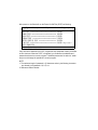
After power on, the Switch will run the Power-On-Self-Test (POST) as following:
CopyRight © 1998, 24 ports 10/100Mbps Switch Console Program (v1.00)
•••••••••••••••••••••••••••••••••••••••••••••••••••
••••••••••••••••••••••••••••••••••••••••••••••••
•••••••••••••••••••••••••••••••••••••••••••••••••
••••••••••••••••••••••••••••••••••••••••••••••
••••••••••••••••••••••••••••••••••
•••••••••••••••••••••••••••••••••••••••••••••••••••
!
If any test item is failed then the POST program will stop and please contact your dealer
to solve the issue. When the POST is completed, you could enter the administrator’s
password and enter the console program. The default password of the switch is “admin”
and you could change the password in console program.
NOTE:
1. The maximum length of password is 15 characters and only the following characters
are allowed in the password: 0-9, A-Z, a-z2. SIM means Slide-In Module
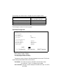
After you login the console program successfully, the first startup screen will show as
below
CopyRight © 24 ports 10/100Mbps Switch Console Program (v1.00)
1. Port Status/Configuration
2. Unit/VLAN Information
3. Trunk Ports Configuration
4. Password Change
5. Warm Start
6. Factory Reset
“TAB” Select item
There are six items listed in the main menu screen.
1. Port Status/Configuration
This item is used to check the current port status and setup the port configuration, like
full-duplex mode, NWay support, Back pressure and Flow control.
2. Unit/VLAN Information
The hardware version of the unit and the virtual LAN setting will display in this item
3. Trunk Ports Configuration
This item is used to setup the port trunk function. There are total six trunk groups
could be configured as following table:
Trunk Group
Trunk Ports
Trunk-A
1, 2, 13, 14
Trunk-B
3, 4, 15, 16
Trunk-C
5, 6, 17, 18
Trunk-D
7, 8, 19, 20
Trunk-E
9, 10, 21, 22
Trunk-F
11, 12, 23, 24
4. Password Change
Use this item to change the administrator's password
5. Warm Start
Select this item will reset the system
6. Factory Reset
This item will reset the system to the factory default setting
The following is the function keys to navigate the console program screens
To do this …
Control Key
Highlight an item
Tab, moves from one item to the
other or one field to the other
Select an item
Enter
Toggle between items in a choice field
Spacebar
Move to next field or item
Tab
The following are screens for console program.
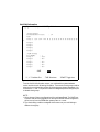
Port Status/Configuration
CopyRight © 1999, 24 ports 10/100Mbps Switch
!""#"$%&"'
()%()&"'
*
%&"'
!"("%&"'
SAVE
“<”, “>” : Prev/Next Port
EXIT
“TAB” Select item
“SPACE” Toggle item
Flow Control: Enable or Disable
Back Pressure: Enable or Disable
Port Full Duplex: Enable or Disable
Port Nway Support: Enable or Disable
There are two portion of the port information displayed on the screen. The first one
is [Port Status] and the detail function work as below:
Port Number: The number of the port is selected to be monitored or setup.
You could use "<" and ">" to change the port number
Port Link Status: This item is used to display the link status of the port - link UP or
link DOWN
Port Speed: The item is showing current link speed between the UTP port and the
connected partner
The second portion is [Port Configuration] and users could use "SPACE" bar to
change the setting. For example:
Port Full Duplex: Full-duplex capability of the port could be enabled or disabled.
NOTE: When the NWay capability is enabled, the full-duplex mode could not
be disabled
Port NWay Support: This item is used to setup the NWay capability of the UTP port
Back Pressure: Enable or Disable the back pressure function of the UTP port
under half-duplex operation
Flow Control: Enable or Disable the flow control function of the UTP port under
full-duplex operation
NOTE: All the change of the port configuration will be real-time effected. The SAVE
item is used to save all the configuration into the system PROM and the
configuration will be boot up from the PROM after system power on or reset.
Unit/VLAN Information
CopyRight © 1998, 24 ports 10/100Mbps Switch
02
)
)
+(,
-
,.
/.0123456701234567000001
/
/
/#
/&
/!
,. /.%8
'
/%'
/%'
/#%'
/&%'
/!%'
SAVE
“<”, “>” : Prev/Next Port
EXIT
“TAB” Select item
“SPACE” Toggle item
From the Unit/VLAN Information screen, you could read the system hardware
version and the virtual LAN setting information. There are six virtual groups could be
setup and you could read the real-time VLAN workgroups change immediately. You
could use the "<" and ">" keystroke to select the designated port and assign the port
to related virtual groups.
NOTE:
1. All the change of the port configuration will be real-time effected. The SAVE item
is used to save all the configuration into the system PROM and the configuration
will be boot up from the PROM after system power on or reset.
2. The virtual setting could be overlapped which means one port could belong to
different virtual group
3. If the trunk is enabled then all the ports belong to that trunk need to be set in the
same virtual workgroup. For example:
<Assumption>
Trunk A is enabled (Trunk A includes port 1, 2, 13, and 14)
<VLAN setting>
When the virtual LAN is setup, the port 1, 2, 13, and 14 must belong to the same
VLAN groups.
Trunk Ports Configuration
CopyRight © 1999, 24 ports 10/100Mbps Switch
)
.%'
%'
%'
#%'
&%'
!%'
SAVE
“TAB” Select item
EXIT
“SPACE” Toggle item
The Port Trunk screen includes six port trunk groups could be setup by administrator.
The port trunk group and UTP ports mapping is listed as below
When the port trunk is enabled, it could build up an 800Mbps bandwidth between
switch to switch connection.
Password Change
CopyRight © 1999, 24 ports 10/100Mbps Switch
Password Change
Current Password:
Valid Characters: 0-9, A-Z, a-z
New Password:
Re-Confirm New Password:
NOTE: The maximum length of password is 15 characters and only the following
characters are allowed in the password: 0-9, A-Z, a-z
Warm Start
CopyRight © 1998, 24 ports 10/100Mbps Switch
Want to do System Warm Start ? <Y/N>
POST ……….
Factory Reset
CopyRight © 1998, 24 ports 10/100Mbps Switch
Want to reset system to factory default values ? <Y/N>
POST ……….
6. Product Specifications
Standard
Interface
Cable Connections
Network Data Rate
Transmission Mode
LED indications
System Buffer Memory
MAC Address Table
Filtering/Forwarding Rate
Emission
Operating Temperature
Operating Humidity
Power Supply
IEEE802.3, 10BASE-T
IEEE802.3u, 100BASE-TX
RJ-45 x 24 NWay switching ports
One uplink port (an alternative to port 24)
One slide-in module for fiber connection on the back
One RS-232 console port
RJ-45 (10BASE-T) : UTP Category 3,4,5
RJ-45 (100BASE-TX) : UTP Category 5
Auto-negotiation (10Mbps, 100Mbps)
Auto-negotiation (Full-duplex, Half-duplex)
System
Power x1
Module x1
Fiber Link x1
VLAN x1, TRUNK x1
VLAN/Trunk x6
Port
100M
Link/Activity
FDX/COL
Slide-in module
Link/Act, FDX/COL
3MByte
1K entries
10Mbps: 14,880pps/14,880pps
100Mbps: 148,800pps/148,800pps
FCC Class A, CE
00 ~ 550C (320 ~ 1310F)
10% - 90%
100~240 VAC, 50/60 Hz