1
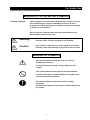
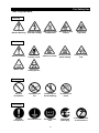
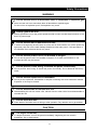
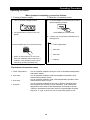
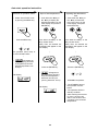
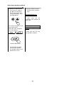
INSTRUCTION MANUAL
FOR
CLEAN OVEN
Model
DE410/DE610/DT410/DT610
DE410U/610U
Version 7
●Thank you very much for buying Yamato Scientific
DE,DT,DEU series.
●For proper use of this unit, please read the instruction
manual and warranty thoroughly before operation. Keep
both for any future references.
Warning:Read and apprehend the important warning
signs in this instruction prior to use.
Yamato Scientific
This paper has been printed on recycled paper.
Table of Contents
For Safety Use ........................................................................................................................................1
Explanation of illustrated symbols ....................................................................................................1
Table of Symbol Mark.......................................................................................................................2
Safety Precautions .................................................................................................................................3
Installation and Preparation for Use .................................................................................................4
About the inhalation port...................................................................................................................8
Precautions in Handling ........................................................................................................................9
Emergent Troubleshooting .................................................................................................................13
Identification of “TROUBLE” and Error Code/Causes....................................................................13
Identification of Parts...........................................................................................................................14
Main unit .........................................................................................................................................14
Control Panel ..................................................................................................................................15
Safety Precaution and Check..............................................................................................................17
Operating Procedure............................................................................................................................18
Operating Procedure ......................................................................................................................18
Fixed temperature operation instructions .......................................................................................19
Auto start operation instruction.......................................................................................................20
Auto stop operation method ...........................................................................................................21
Programmed operation method......................................................................................................23
Switching from one operation to another........................................................................................24
Method of using DISPLAY key ............................................................................................................25
How to use the MODE..........................................................................................................................26
Content of function menu ...............................................................................................................26
Calibration Offset Function .................................................................................................................27
Outline of Function..........................................................................................................................27
Calibration Offset Function .............................................................................................................27
Setting the calibration offset function..............................................................................................28
Safety Devices and Error Codes.........................................................................................................29
Independent overheat prevention...................................................................................................30
Behavior after Power Restoration ......................................................................................................31
Maintenance and Inspection ...............................................................................................................32
Periodic inspection/Maintenance....................................................................................................32
Replacement of the HEPA filter......................................................................................................32
Long Storage ........................................................................................................................................33
Long storage and disposal .............................................................................................................33
After service and WARRANTY ............................................................................................................34
Specifications .......................................................................................................................................35
Wiring Diagram.....................................................................................................................................37
Replacement parts table......................................................................................................................39
Hazardous Material ..............................................................................................................................42
List of Symbols in the display.............................................................................................................43
Operational Procedures of Type Ⅳ Controller ................................................................................47
Run “MENU” ...................................................................................................................................47
Program “MODE”............................................................................................................................48
Flowchart for programming.............................................................................................................49
For Safety Use
Explanation of illustrated symbols
MEANING OF ILLUSTRATED SYMBOLS
Illustrated Symbols
Various symbols are used in this safety manual in order to use the
unit without danger of injury and damage of the unit. A list of
problems caused by ignoring the warnings and improper handling
is divided as shown below.
Be sure that you understand the warnings and cautions in this
manual before operating the unit.
Warning
If the warning is ignored, there is the danger of a problem
that may cause a serious accident or even fatality.
Caution
If the caution is ignored, there is the danger of a problem
that may cause injury/damage to property or the unit itself.
MEANING OF SYMBOLS
This symbol indicates items that urge the warning
(including the caution).
A detailed warning message is shown adjacent to the
symbol.
This symbol indicates items that are strictly prohibited.
A detailed message is shown adjacent to the symbol with
specific actions not to perform.
This symbol indicates items that should be always
preformed.
A detailed message with instructions is shown adjacent to
the symbol.
1
For Safety Use
Table of Symbol Mark
Warning
General Warning
Warning of High
Potential voltage
Warning of High
Temperature
Warning of drive
section
Warning of
explosion
Caution
Caution of scald
Caution of lowwater boiling
Prohibition of
fire
Prohibition of
disassembling
Prohibition of
touch
Ground the unit
Install on level
area
Pull electric
power plug
General Caution
Caution of
electric shock
Water only
Caution of
deadly poison
Caution of water
leak
Prohibition
General
Prohibition
Compulsion
General
Compulsion
2
Fixed time check
or maintenance
Safety Precautions
WARNING
Do not use the unit in an area where there is flammable or explosive gas.
■ Never use the unit in an area where there is flammable or explosive gas.
For the unit is not explosion-proof, fire/explosion may result.
Always ground the unit.
■ Always ground the unit on the power equipment side in order to avoid electrical shock or fire
due to a power surge.
Do not use this unit if malfunction occurs.
■ If smoke or strange odor should come out of the unit for some reason, turn off the power key
right away, then turn off the earth leakage breaker and the main power. If this procedure is
not followed, fire or electrical shock may result.
Do not use the power cord if it is bundled or tangled.
■ Do not use the power cord if it is bundled or tangled. If it is used in this manner, it can
overheat and fire may be caused.
Do not process, bend, wring, or stretch the power cord forcibly.
■ Do not process, bend, wring, or stretch the power cord forcibly. Fire or electrical shock may
result.
Do not use the explosives or flammables.
■ Do not put the explosives, flammables or samples containing with such hazardous material.
Explosion or fire may be caused.
Do not disassemble or remodel this unit.
■ Disassembling this unit can cause a fire, electric shock or other crisis. Never disassemble or
remodel this unit.
Do not touch hot area.
■ Some areas of the boiler are hot during or after operation. Pay attention not to get scalded.
CAUTION
If it begins to thunder.
■ If it begins to thunder, turn off the power immediately. Neglecting this can result in
breakdown, fire or electricshock.
3
Safety Precautions
Installation and Preparation for Use
Warning
1.Ground the unit.
If you do not ground the unit, the earth leakage circuit breaker would not work in case of
electric leakage. Be sure to connect the ground lead (green core line of the power cord)
to the ground wire or terminal of the power source. Contact an electrician if you have no
equipment for grounding.
DE410/DE610, DT410/DT610, DE410U/610U is AC200V three-phase specification.
Connect the unit certainly with AC200V outlet or power distribution switchboard.
2.Choose a proper place for installation.
Do not install the oven in a place where:
・Flammable gas or corrosive gas is generated.
・Ambient temperature exceeds 35℃.
・Ambient temperature fluctuates violently.
・There is excessive humidity and bust.
・There is direct sunlight.
・ There are constant vibrations.
Keep the following clearance around the oven.
More
More
4
Safety Precautions
Installation and Preparation for Use
Warning
3.Choose a correct power distribution board or receptacle.
Choose a correct power distribution switchboard or receptacle that meets the oven’s
rated electric capacity.
Electric capacity :
DE410 AC200V three-phase
8.3A
DE610 AV200V three-phase 11.5A
DT410 AV200V three-phase 11.5A
DT610 AV200V three-phase 16.0A
DE410U AV200V three-phase
8.3A
DE610U AV200V three-phase 11.5A
4.Supply connections for the oven
・Request the supply connection for the shingle-phase 220V specifications from a
licensed electrician.
・The special knowledge and skill are required for connecting. Failure to have this
operation complete by certified personnel will cause a fire or electrical shock during
oven operation.
5.Do not use the unit in an area where there is flammable or explosive gas.
Never use the unit in an area where there is flammable or explosive gas. The unit is not
explosion-proof. An arc may be generated when the power switch is turned ON or OFF,
and fire/explosion may result.
Explosive gas
Flammable gas
5
Safety Precautions
Installation and Preparation for Use
Warning
6. Do not remodel the oven
7. Install the Oven on a level area.
Unauthorized modification will be hazardous
and cause problems in the operation of the
Oven.
Do not installation the oven on a non level surface.
This will cause hazards to the operator and create
problems during actual operation.
Remodeling
Caution
After installed, you should:
● It may cause injure to a person if this oven falls down or moves by the earthquake
and the Impact, etc…
● To prevent, take measures that the unit cannot fall down.
● Ask the special trader how to fix the unit, because the way of fixing is different with the
floor structure.
(Example)
The example of our preventing the Oven falling down is putting the level-adjuster to the unit
(special modification needed) and fixing metal fitting adjuster to the floor.
(Ask the special trader how to fix the unit to the floor.)
6
Safety Precautions
Installation and Preparation for Use
Warning
Handling of power code.
● Do not use the power cord if it is bundled or tangled. If it is used in this manner, it can
overheat and fire may be caused.
● Do not process, bend, wring, or stretch the power cord forcibly. Fire or electrical shock
may result.
● Do not put the power cord under the desk, chair, etc., or through an object.
electrical shock may be result.
Fire or
● Do not run the power cord next to heating equipment such as a heater. The cover of
the cord may melt and fire or electrical shock may result.
●
When the power cord is damaged (exposure of the core wires, disconnection, etc.),
turn off the power key right immediately, then turn off the earth leakage breaker and
the main power. Contact customer service for a replacement immediately. If this
procedure is not followed, fire or electrical shock may be caused.
● Connect power code certainly with proper power distribution switchboard or outlet.
Caution in setting shelves
● Do not use any shelves but the attached ones.
If it is used in this manner, the oven cannot occasionally regulate temperatures
properly.
● Put the attached shelves on the shelf brackets fitted to the chamber when you use the
oven.
7
Safety Precautions
About the inhalation port
Warning
Ventilating
● When forwarding the unit, the intake port is closed. If you use the unit with the
exhaust damper opened to ventilate more effectively, you should remove the cover of
the intake port in advance as follows.
1. Turn off the power of this unit and circuit breaker in advance.
2. Take off the four connecting screws at the right side to the body, and take off the
exterior cover of the right side.
3. There is the closed intake port around the center of this side (See the figure below) of
the motor that is at the bottom of the body chamber. Take off the four connecting
screws, and take off the intake port cover.
4. Install the exterior cover of the right side as it was.
Be sure not to lose the intake port cover and connecting screws removed.
Be sure to turn off the power of this unit and circuit breaker in advance before doing this
work.
Inhalation
port
Exterior cover of
the right side
Inhalation port cover
For the hot wind or gases of the samples are discharged from the exhaust duct, you
should modify the duct.
8
Precautions in Handling
Warning
Substance that can be used
Never use explosive substances, flammable substances (shown on page 42 “hazardous
Material”), and substances that include explosive or flammable ingredients in the unit.
explosion or fire may occur.
Do not use this unit if malfunction occurs. You should:
If smoke or strange odor should come out of the unit some reason, turn off the power key
right away, the turn off the earth leakage breaker and the main power.
Immediately contact a service technician for inspection. If this procedure is not followed,
fire or electrical shock may result.
Never perform repair work yourself, since it is dangerous and not recommended.
Do not put the foreign substances in the oven.
Don not put a foreign substances such as metals or flammable substances in the port of
the unit (ventilation hole and exhaust port, etc.). If this procedure is not followed, fire,
electrical shock or burn may result.
If the foreign substances enter the unit, turn off the earth leakage breaker immediately and
contact a service technician for inspection. If this procedure is not followed, fire, electrical
shock or burn may result.
Caution in taking out samples
During and immediately after operation, the internal surfaces of the chamber and the door
are extremely “HOT”. To prevent injury, wear thick gloves while taking out the sample.
When you open the door during working at the high temperature.
Do not touch the internal surfaces of the chamber and the door when you open the door at
the high temperature, because they are extremely hot.
To open the door while the chamber is still hot may cause the malfunction of a fire detector
if it is installed near the oven.
Do not touch heated parts.
Do not touch the door during or immediately after operation. Severe burning injury may be
caused due to the high temperature.
9
Precautions in Handling
Caution
1. When you use the oven for the first time
During the initial operation, the oven may occasionally generate an odor especially when
high temperature are reached. This odor is normal and deose not signal a problem with the
oven. The adhesive on the insulation melting causes the nature of the odor.
2. When you open the exhaust duct to its full width
When you open the exhaust duct to its full width, the time toward the maximum high
temperature to use and air cleanliness may not be satisfied with class 100. When you open
the inhalation port to its full width, it may not reach to the maximum high temperature to
use.
3. Caution about a drenched sample
When using a wet sample, try to drain it by heating it by heating with the ventilation damper
opened. If water is adhered to the inside of the unit, it may cause electric shock, machine
trouble, or weakness of HEPA filter.
Do not use a very wet sample as it is.
4. Caution about samples
To be uniform the temperature distribution in the chamber, it is circulated whit the
ventilation. When you use a powder sample or a small sample, be sure not to be scattered,
if the flammable materials or metal to in the heater, it may cause fire ir electric shock.
It occasionally takes a long time before the chamber reaches the target temperature if the
camber is congested with samples or a sample with the large specific heat is in it. In such
cases, reduce samples. Moreover, note that the temperature display occasionally unsettle
when you process the sample that generate heat (Only the case that the sample itself is not
explosive, combustible, or ignitable substances).
5. Distribute sample
Each shelf can carry a uniform load of 30 ㎏. Do not put heavier sample than it.
When you place samples on a shelf, distribute them evenly over the shelf area.
If a shelf is congested with sample, the oven occasionally cannot regulate temperatures
properly. To ensure the oven’s temperature accuracy, there should be open space of at
least 30% on each shelf.
6. Do not climb on the oven
Do not climb on top of the oven because it will fall down and break.
Failure to observe this caution may cause injury to a person.
10
Precautions in Handling
Caution
7. Do not put anything on the oven.
Do not put anything on top pf the oven because they will fall and result in injury to a
person.
8. During a thunderstorm.
During a thunderstorm, immediately turn off the earth leakage beraker and main power.
9. In case of power failure.
Once the power supply has been cut off due to power failure, and then the power supply is
restored, the oven will resume running. (See page31 “Behavior after Power Restoration”
about details.)
10. About the independent overheating prevention.
For safety use, be sure to set the independent overheating prevention. The temperature
set of the independent overheating prevention must be 15℃ higher than the set of the
temperature adjustment.
11. Caution about the temperature range.
Use the oven in the range of room temperature +30℃ to 260℃ for DE610.
If you use the machine out of temperature range, it may cause machine trouble or
accident.
11
Precaution in Handling
Caution
12. Do not place any samples on the bottom of the chamber
Do not place any samples on the bottom of the chamber to heat, because it may cause
that the unit does not work correctly, that the temperature become extraordinary high, and
that machine trouble occurs. Put the samples on the attached shelves and set the shelves
on the metal shelf brackets.
Sample
13. Never use corrosive samples
The main route of the circulation wind is made of stainless steel (SUS304). However,
strong acid occasionally corrodes even stainless steel. Besides this, the silicone rubber
packing is also vulnerable to acid, alkali, oil and halogens’ solvents.
14. When you open and shut the door
Do not put your hand either face near the door when you open and shit the door. Failure to
observe this caution may result in injury because the door hits your hand or face.
15. When you use the cable hole
When you insert the sensor or probe for measurement into the cable hole, close the cover
of the cable hole as much as you can, and seal up an opening with a cover, a
heat-resistance gasket or a sealant. When the seal is not much enough, air cleanliness or
temperature specification may decline.
12
Emergent Troubleshooting
Identification of “TROUBLE” and Error Code/Causes
blinks
blinks
blinks
TROUBLE lamp flashes.
TROUBLE lamp flashes.
TROUBLE lamp flashes.
Trouble in temperature
sensor.
Trouble in heater control
materials.
Heater circuit is
disconnected.
、
、
blinks
blinks
etc. blinks
TROUBLE lamp flashes.
TROUBLE lamp flashes.
Bad quality in heater circuit.
Bad quality in electronic
circuit.
Troubleshooting
blinks
TROUBLE lamp flashes.
Running of independent
overheating prevention
TROUBLE lamp flashes.
Trouble in fan.
● When these error code comes up, record the error code, and
turn off the power immediately.
● If a problem occurs with the Drying Oven, you need exchange
some parts or inspect the unit. Contact our sales or service
representative. When you contact, tell the error code blinked.
(See to page 34 “After service and WARRANTY”.
Note) The measurement temperature “250” in figure is example.
13
Identification of Parts
Main unit
Exhaust duct
Exhaust damper knob
Differential
pressure gage
Control panel
Cable hole
Door
Door handle
Power code
Earth leakage breaker
14
Identification of Parts
Control Panel
The Control Panel is shown at Fig.3.3, and the identification of Parts is shown as below.
If you need detailed explanation about the specification, function, and operation about controller,
refer to the attached instruction manual.
⑱
⑰
⑯
⑫
⑨
⑪f
⑪d
⑪e
⑪ ⑪a
⑪b
⑪c
⑭
②
①
③
④
⑮
⑩
⑧
Fig.3.3
⑥⑦
⑬
⑤
Control Panel
①
POWER key:
Key to make the controller ON/OFF.
②
MODE key:
③
DISPLAY key:
④
MENU key:
⑤
ENTER key:
Key to select a function from program input, edit, delete modes, hour/time
setting, change-over mode, and other functions.
Key to change-over the display content of the sub display(10).
Display content is changed over to set temperature, remaining time, hour,
execution segment No.
Key to select the operation mode. Each mode of fixed temperature,
auto-start, auto-stop and program operation can be selected.
Key to determine the input value of set value (temperature, time, hour,
etc.), selection mode, execution segment No. etc.
⑥⑦▼▲(UP/DOWN)key Key to change set value (temperature, time, hour, etc.) and to choose a
selection from various parameters on the function menu.
15
Identification of Parts
⑧
ESCAPE key:
⑨
Main display:
⑩
Sub display:
⑪
Operation monitor:
⑪a STANDBY lamp:
⑪b Temperature
pattern lamp:
⑪c OVER lamp:
⑪d TROUBLE lamp:
⑪e REMOTE operation
indicator lamp:
⑪f KEY LOCK indicator
lamp:
⑫
Operation menu
indicator lamp:
⑬
⑭
Key to cancel the latest entry and recover the status was valid prior to
the making the selection.
It displays temperature measurements, set values (temperature time,
hour, etc.), program information, error information, etc.
It displays set temperature, remaining time, current hour and
execution segment No. etc.
It indicates an operation mode.
It flashes to indicate that instrument is in the preoperational standby
mode.
It illuminates to indicate the heat treatment process pattern executed
by the controller with flashing light indicating the point currently in
execution.
It flashes to indicate the end of auto-stop or program operation.
It blinks when an error is detected and displays the corresponding
code for that particular problem.
It illuminates when the instrument is put into remote operation
(optional) and displays the word “REMOTE”.
It illuminates to indicate that the operation panel key lock function is in
operation.
It illuminates to indicate the active operation mode in the operation
menu.
indicator lamp:
It illuminates to indicate the item (set temperature, remaining time,
hour or execution segment) shown in the sub display.
HEAT ON indicator
It illuminates when the heater is on.
Sub display menu
lamp:
⑮
TIME indicator
lamp:
⑯
Independent
Temperature
Overheating
Prevention Device:
⑰
Differential
pressure gage:
⑱
Exhaust damper
knob:
It illuminates when the operation starting time if the auto-start and the
operation completion time if the auto-stop is set in the hour setting
mode.
Setting the instrument to the operation temperature of the
independent over rising prevention.
It illuminates to indicate the difference HEPA filter. It help you to
decide the time for exchanging.
It is the adjustment knob of width of exhaust damper. The indication
value is a standard.
16
Safety Precaution and Check
Warning
If you do not ground the unit, the earth leakage circuit breaker would not work in case of electric
leakage. Be sure to connect the ground lead (green core line of the power cord) to the ground wire
o terminal of the power source.
● Do not connect the grounding wire to a gas pipe or water pipe.
● Do not connect the divergence outlet because the generation of heat will occur.
● Do not use the unit in an area where there is flammable or corrosive gas.
Caution
Checking the outlet.
● Connect the power code with the correct power distribution switchboard or receptacle. When
you use the three-phase electric power and connect the opposite phase, the fan may spin the
opposite way and the oven may not run normally. When you connect the opposite phase, the
indicator of the Differential pressure gage dose not increases. Connect again after checking the
wiring diagram (page37~page38).
Checking the safety
● Be sure to set the independent overheating prevention 15℃ higher than the temperature inside
the unit running.
17
Operating Procedure
Operating Procedure
When prepared completely, proceed as follows:
1. Turning of power supply
2. Selection of operation menu
z
Turn on the earth leakage breaker.
z
The present time is shown on the sub
display.
z
Press the MENU key several times to select
desired operating method.
Press MENU key several times
z
↓
Push the POWER key in the operation panel.
It allows you to enter each parameter into a
flashing menu.
○ Fixed Temperature
↓
○ Auto start
↓
○ Auto stop
z
↓
When once the power is on, this oven
becomes a standby state. Under such a
condition, every operation mode can be
selected by pushing the MENU key.
○ Program
Explanation of operation menu
1. Fixed Temperature
2. Auto start
3. Auto stop
4. Program
: It is an operation method to bring the oven to the desired temperature
and keep it steady.
: It is an operation method to start the temperature operation when
reached the set time or hours.
: It is an operation method to stop a fixed temperature operation when
reached the set time or hours.
: It is an operation method that can start or stop an operation either
when reached the set time or hours. Moreover, it can change the
temperature when reached the desired time and repeat to do that.
※Refer o the attached instruction manual “Programmable controller
high-tech Ⅳ type” to know the way to input the program or edit.
18
Fixed temperature operation instructions
Selection of operation menu
z
Push the MENU key and
select the fixed
temperature operation
Input of set temperature
z
Push the ENTER key after
making a sub-display
display an arbitrary set
temperature pushing ▲▼
keys.
Changing the set
temperature when fixed
temp operation is in
progress
z
Push either the ▲key or
the ▼key to display the
desired temperature on the
main display and push the
ENTER key
Push the MENU key
Press either the ▲key or the
▼key several times.
Press either the ▲key or the
▼key several times.
↓
(Note) Then, the desired set
temperature will appear on the
main display.
(Note) Then, the desired set
temperature will appear on the
main display.
The lamp of the FIXD TEMP
blinks.
↓
↓
Press the ENTER key.
Press the ENTER key.
↓
z The temperature set last
time is blinking and enters
the state that a set
temperature can be input
in a sub-display.
z
The oven will start to run
the fixed temperature
operation to the renewed
temperature.
19
z
The oven will start to run
the fixed temperature
operation to the renewed
temperature.
Auto start operation instruction
Selection of operation menu
z
Select Auto START mode
by pushing the MENU key.
Input of set temperature
z
Push either the ▲key or
the ▼key to display the
desired temperature on the
main display and push the
ENTER key
Inputting the desired set
time
z
Push either the ▲key or
the ▼key to blink start
time (or the hour) on the
main display, and press
the ENTER key
Push the MENU key
Press either the ▲key or the
▼key several times.
Press either the ▲key or the
▼key several times.
↓
(Note) Then, the desired set
temperature will appear on the
main display.
(Note) Then, the desired set
temperature will appear on the
main display.
The operation menu lamp of
an AUTO START blinks.
↓
↓
Press the ENTER key.
Press the ENTER key.
↓
↓
↓
z
will appear on
the sub display (omission
of temperature) and the
desired temperature can
be input.
z
Sub display
will appear on
the sub display (showing
time) and the operation
start time can be input.
(running start time・hours)
STANDBY lamp blinks.
z
The STANDBY lamp of
the operation monitor
blinks.
z The operation will be in
standby condition.
z After reaching the set time
(or hour), the oven will
start to run the auto start
operation to the renewed
temperature.
Sub display
20
Auto stop operation method
Selection of operation menu
z
Press the MENU key and
select the auto stop
operation.
Input of set temperature
z
Push either the ▲key or
the ▼key to blink the
desired temperature on the
main display and push the
ENTER key
Inputting the desired set
time
z
Push either the ▲key or
the ▼key to blink your
desired time (or the hour)
for operation stop on the
main display, and press
the ENTER key
Push the MENU key
Press either the ▲key or the
▼key several times.
Press either the ▲key or the
▼key several times.
↓
(Note) Then, the desired set
temperature will appear on the
main display.
(Note) Then, the desired stop
time (or hour) will appear on
the main display.
The menu lamp of an AUTO
STOP blinks.
↓
↓
Press the ENTER key.
Press the ENTER key.
↓
↓
↓
z
will appear on
the sub display (omission
of temperature) and the
desired temperature can
be input.
z
Sub display
will appear on
the sub display and the
operation stop time can be
input. (running stop time or
hours)
Sub display
z
will appear on
the sub display and you
can shoes the wait
function to be activated or
not.
Sub display
21
Auto stop operation method
Working conditions of timer
Selection of wait function
z
Press either the ▲key or
the ▼key to indicate the
wait function (ON or OFF)
on the main display. Then
press ENTER key.
z
Auto stop timer activates
when:
The wait function is on,
It starts when the set
temperature has reached the
target valve.
Press either the ▲key or the
▼key several times.
Either ON or OFF will appear
on the main display.
The waiting function is off or
the time setting represents
hours,
It starts right after the auto
stop operation is started.
(activate)
(inactive)
↓
Press the ENTER key.
↓
z
This operation activates
the auto stop operation.
The operation stops on the
desired time or hour.
22
Programmed operation method
Selection of operation menu
z
Press the MENU key and
select the programmed
operation.
Input of set temperature
z
Push either the ▲key or
the ▼key to indicate an
desired program number
on the main display, and
press the ENTER key
Input of time
z
Push the MENU key
Press either the ▲key or the
▼key several times.
Press either the ▲key or the
▼key several times.
↓
The program number will
appear on the main display.
The desired set time will
appear on the main display.
↓
NOTE:
The operation menu lamp of
the PROGRAM blinks.
if no programs have been set, -
is blinking.
See the Operating Instructions for
Programmable Controller to set a
new program.
↓
z
Push either the ▲key or
the ▼key to blink your
desired operation start
time (or hour) on the main
display, and press the
ENTER key
↓
Press the ENTER key.
will appear on
the sub display and the
execution program number
can be input.
↓
Press the ENTER key.
↓
z
Sub display
will appear on
the sub display and the
operation stop time can be
input. (running stop time or
hours)
Sub display
23
z
The standby lamp on the
operation monitor blinks.
(Operation is in STANDBY
MODE)
z The operation will start
after the set time is up.
Switching from one operation to another
This instrument can switch to a different operation mode without stopping the current program
no matter what mode it is in, fixed temperature operation, auto-start/stop operation, and
program operation.
Selection of operation menu
z
Press the MENU key several times unit the
desired operation menu lamp flashes on the
Operation Menu.
z
Since the current operation has not stopped, the
operation menu lamp is also lit.
Press MENU key several times.
↓
z
This status allows you to enter each parameter
into blinking or lighting operation menu.
↓
z
The lamp blinks or lights.
The next step is the same as each operation.
(See to page19~page23)
24
Method of using DISPLAY key
The display content of the sub display can be changed over by turns when pushed the DISPLAY
key.
Operation mode
Set temperature
Fixed temperature
operation
Hour
Remaining time
Standby
Hour
Auto sart
operation
Set temperature
During operation
Remaining time(*1)
Hour
Set temperature
During operation
Auto stop
operation
Remaining time(*2)
Hour
After time is up
Hour
Remaining time
Standby
Hour
Set temperature
Remaining time
Program operation
During operation
Hour
Execution segment(*3)
After time is up
Hour
*1: HOLD is displayed.
is displayed in the waiting state.
*2: When the wait function is set to on,
*3: The DISPLAY key will enable to show the rest of the repeat cont while the repeat operation.
25
How to use the MODE
Content of function menu
This controller has the other functions bellow. you can choose the function by using the mode key
and the ▲key or the ▼key.
z
Press the mode key.
Press the MODE key and display your desired
function on the main display by pushing either the ▼
key or the ▲key. Each function will appear by turns
whenever pushing the ▼/▲keys.
↓
Select with the ▼key
or the ▲key.
Main display
Function
Inputting and editing
To input and edit the program.
program
Deleting the program
Switching time
setting mode
Setting and releasing
the key lock
Alarm buzzer
ON/OFF function
Accumulating time
display function
To delete existing programs that are no longer
necessary. (It is displayed only when he program is
inputted)
To input either an hour or a period of time during
time setting process.
※It is set to the time (a period of time) setting mode
when the product was shipped from the factory.
This function is for protecting wrong key actions
during the operation or while being in the standby
state.
To select whether you want to activate the alarm
buzzer or not when an error occues.
To display the total duration that the POWER key is
on, within the range of 0 to 49999 hours.
Hold function
To hold the operation that is currently running. This
function will get active to stop the count of desired
time that is currently running. (This function is
display only under operation)
Date and current
To set the date and hour.
hour setting function
Calibration offset
function
To conform the display temperature to the
measurement temperature of a voluntary point in the
chamber at a voluntary temperature. Details are
described on next page.
※The detail of the function menu is mentioned on the attached instruction manual “Programmable
controller high-tech Ⅳ type”.
26
Calibration Offset Function
Outline of Function
In the controller, the relationship between the temperature T detected by the sensor and the
display temperature of the operation panel D is expressed by the equation of the line which passes
the two points (T0, D0) and (Ts, Ds) shown in Fig.1.
Display temperature
Here, T0 is the sensor detecting temperature when the
chamber
central temperature becomes the zero
adjusting temperature (normally room temperature is adopted)
D0 at the time of no load, Ts is the sensor detecting
temperature when the chamber central temperature becomes
the span adjustment temperature (normally working maximum
temperature is adopted) Ds at the time of no load in the same
way.
(Controlled temperature)
DS
y=ax+b
D0
T0
TS
Sensor detection temperature
Fig. 1
As it is clear from the facts above, conforming of the chamber
central temperature and the display temperature is guaranteed
only when there is no load and at two points shown above.
In other words, it is possible for a temperature measured at a point in the chamber does not conform
to the display temperature of the operation panel at a voluntary temperature without load. This is the
function to move the line which passes above two points to the Y axis direction in parallel (increase
or decrease y intercept of the line). The parallel movement amount including a sign is defined as the
calibration offset. This function can conform the display temperature of the operation panel to the
measurement temperature of a voluntary point in the chamber at a voluntary temperature.
Calibration Offset Function
Display temperature
(Controlled temperature)
Parallel
movement
DSV
△DCAL
DPV
T
T
i
V
Sensor detection temperature
Fig. 2
In Fig. 2 Dsv is a display temperature of the operation panel
nder the condition hat temperature in the chamber is constant
for a set temperature. It is natural to say that this value is equal
to the target set temperature. DPV is a measurement
temperature of a voluntary point in the chamber under this
condition. The difference between DPV and Dsv including the
sign is defined as the calibration offset. Therefore offset is
shown as
ΔDb = DPV − DSV
Equation 1
In Fig. 2, △Db becomes the negative value since the target set
temperature DSV is larger than the actually measured
temperature DPV.
NOTE: Setting Tolerance of Calibration Offset
・The setting tolerance of the calibration offset is ±14℃ for DE610. Initial off set value has
been set to 0℃ when shipping.
27
Setting the calibration offset function
This function can be activated when the controller is in the condition of accepting the MODE key.
EX.
Bring the oven to the target set temperature 100℃ and allow it to reach the steady state.
After then, measure the temperature at a point in the chamber. If it shows 97℃ when the
main display shows 100℃, you can conform your measuring value to the one on the
display by using calibration offset function.
Calibration offset △Db is obtained from the Equation 1 (page27) as shown below.
△Db:97℃-100℃=-3℃
procedures to set the calibration offset △Db to the controller are shown as below.
Procedure and Display
Explanation
z
→
Push the Mode key, and then push the ▲key or
the ▼key several times to display “cAL” on the
main display. The sub display shows the
calibration offset value that has been set the last
time. In this examples, the calibration offset is
Push the ▲or ▼key
Push the MODE key
↓
shown for 0.
※When the unit is shipped from the factory, the
sub-display shows 0 as the calibration offset
value.
Push the ENTER key
z
If you change the calibration offset, push the
ENTER key when the main display shows “cAL”.
Then the sub display shows “cAL”, and the main
display flashes the present calibration offset
value.
Push the ▲key or ▼key
z
push either the ▲key or the ▼key to change
the value on the main display to your desired
value (calibration offset value to be set newly).
In this example, the main display shoes-3.
Push the ENTER key
z
When the changing is completed, push the ENTER
key.
z
The changed value is entered and both the main
and the sub displays return to the display mode just
before pushing MODE key. The controller starts the
temperature controlling operation in order to make
the difference zero, since the difference is
generated between the target set temperature and
the temperature in the chamber by the changing of
the calibration offset value.
28
Safety Devices and Error Codes
This instrument incorporates an automatic diagnosis function built in the controller and safety
devices independent of the controller. The purposes and operations of the safety devices and
countermeasures are shown in the Table below. When an abnormal condition occurs, an error code
is displayed in the main display. Immediate action should be taken according to the specific
counter-measures.
Safety Device
Display
Cause & Counter-measures
1. Earth leakage breaker
No Display
⇒ Report to our service office and check the
cause of the problem
2. Motor thermal Protector
No Display
z
Heater Overheating
⇒ Report to our service office
3. Sensor malfunction detector
TROUBLE lamp flashes
TROUBLE lamp flashes
TROUBLE lamp flashes
TROUBLE lamp flashes
z
Heater circuit is disconnected
z
Trouble in fan
⇒ Report to our service office
flashes
7. Independent overheating
prevention
Short circuit in triac
⇒ Report to our service office
flashes
6. Fan malfunction detector
z
⇒ Report to our service office
flashes
5. Disconnected heater circuit
detector
Break in temperature sensor circuit
⇒ Report to our service office
flashes
4. Triac circuit detector
z
TROUBLE lamp flashes
flashes
z
Incorrect setting of the independent
overheating prevention
⇒ Set correctly
z
Heating of sample
⇒ Reduce the amount of the sample
z
Malfunction of the independent overheating
prevention circuit
⇒ Report to our service office
8. Main relay malfunction
detector
TROUBLE lamp flashes
z
POST function is running (See the attached
instruction manual “Programmable controller
high-tech Ⅳ type”)
flashes
z
Contact Yamato Scientifics’ Technical
Service Department.
flashes
z
The door is opened.
It is not the fault.
TROUBLE lamp flashes
,
10. Door switch
A malfunction of the main relay
⇒ Report to our service office
flashes
9. POST function*
z
will flash
When opened the door,
on the sub display and the heater circuit will
be cut off and the fan will stop for safety.
Once closed the door,
will go out
and the heater circuit and the fan will
resume working.
11. Automatic overheating
preventive function
z
No Display
29
The function of overheating prevention in
controller.
When the temperature detected by sensor is
12℃ higher than the target set temperature,
this function in the controller runs
automatically and the heating stops. When
the differences become less than 12℃, the
function is removed.
Safety Device and Error codes
Independent overheat prevention
There are two safety devices in this unit: the auto-overheating preventive function of the controller
(automatic recovery) and the independent overheating prevention (manual recovery). Circuits and
sensors that are independent from the controller configure them. These safety devices for the
temperature overheating prevention protect the instrument in a fail-safe method.
Setting the Temperature Range and Function
Setting Temperature:
Input Method:
0~399℃
Function:
Heater output is cut off when the measured temperature gets higher than the
set temperature of the independent overheating prevention. The function is
active when the earth leakage breaker is ON.
When the independent overheating prevention is activated, is flashing on the
Three integer digital switch. Turn the drum of each column and set the
desired value. The first integer can only be from 0 to 3 for the hundred
columns.
and TROUBLE lamp flashes. When the
main display with the
independent overheat prevention is active while the heater is in the
and
temperature rising process, etc., and flash alternately
on the display.
Activation/Setting Method
1. Set the independent overheating prevention 15℃ higher than the set temperature of the main unit.
2. The purpose of overheating prevention device is to protect the unit from overheating. It does not
intend to protect the sample, or to protect them from the accident caused by the use of explose or
inflammability.The temperature is set to 280℃ DE410/610,to 220℃ DE410U/610U,to 375℃
DT410/610 at factory shipment.
3. When the independent overheating prevention is activated improperly by changing the setting of the
independent overheating prevention lower than the internal temperature or by continuing operation
with setting the unit at too low temperature, turn off the earth leakage breaker to reset the unit and
perform the setting again. If it is activated by another reason, see chapter of Safety Devices and Error
Codes on page29.
Precautions
1. Only 0 to 3 can be see for the column of hundreds of the digital switch by the stop mechanism;
however, if forced to change it to a value higher than 3, It will damage the unit.
2. Set temperature can change by touching the setter when cleaning. Always confirm that the set
temperature is correct after cleaning or before operation.
30
Behavior after Power Restoration
In case of power failure during operation, the controller resumes the following operations after the
power restoration.
In case of power failure during the program operation
1. The controller automatically resumes the program operation when it left at the power shutdown.
2. When the controller does not resumes the program operation automatically,
※In case that the temperature inside the chamber is outside the specified temperature range based
on the setpoint temperature, the controller foes to the FORECED WAIT STATE until the
temperature inside the chamber comes back to the specified temperature range. When you select
the display of the remaining time by pushing the Display key in this condition, the sub display
shows
.
The timer built-in the controller dose not count as running time for a period of power failure.
Therefore the rest time just before the power failed is the same time as the rest time just after the
power recovered.
In case of power failure during the Auto-Stop operation
The controller automatically resumes to the standby when the Auto-Stop operation left at the power
shutdown.
※In case that the temperature inside the chamber is outside the specified temperature range based
on the setpoint temperature after the power restoration, the controller goes to the FORECED
WAIT STATE until the temperature inside the chamber comes back to the specified temperature
range. When you select the display of the remaining time by pushing the Display key in this
condition, the sub display shows
.
In case that the operation stop time is set in a period of time, the timer built in the controller does
not count as running time for a period of power failure. On the contrary, in case
The timer built-in the controller dose not count as running time for a period of power failure.
Therefore the rest time just before the power failed is the same time as the rest time just after the
power recovered.
In case of power failure while the controller is in standby condition
The controller automatically returns to the standby condition when the standby condition of
auto-start and programmed auto-start left at the power shutdown.
※In case that the operation start time is set in a period time, the timer built in the controller dose not
count as standby time for a period of power failure. On the contrary, in case that the operation
start time is set in hours, the timer built in the controller counts as standby time for a period of
power failure.
When the operation start time reaches during power failure, the controller starts running just after
the power restoration.
In case of power failure during the fixed temperature operation and a soak period of the
Auto-Start operation
When power restoration occurs for the operation that is independent upon time such as the fixed
temperature or a soak period of the Auto-Start operation, the controller resumes running toward to
the preset temperature.
31
Maintenance and Inspection
Periodic inspection/Maintenance
Warning
●Before starting inspection or maintenance, disconnect the power plug from the receptacle.
●Conduct inspection and maintenance only after the oven has cooled down.
●Do not disassemble the oven.
Caution
●When you remove dirt or stains from the unit’s resin parts and the control panel, use a soft wet cloth.
Do not use benzene, thinner, cleanser or a hard brush; it will cause deformation, qualitative
deterioration and/or discoloring of the components.
Every month
●Check the function of the earth leakage breaker.
・Connect the power code and check the function in the condition of electricity running.
・At first, turn the earth leakage breaker “ON”.
・At next, when you push the red test button of the earth leakage breaker with the point of
ballpoint pen, it is normal that the earth leakage breaker becomes “OFF”.
●Check the operation of independent temperature overheating prevention device.
・After executing the fixed temperature operation at the appropriate set temperature, set the
operation temperature of the independent temperature overheating prevention device to
the temperature little lower (about 5℃) than the fixed temperature.
・Under normal circumstances, the heater circuit is cut off in a few seonds and the TROUBLE
lamp and Er.07 flashes at the same time, and the alarm buzzer sounds if the alarm buzzer
function is ON.
※Always perform inspection of the earth leakage breaker and the operation of
independent temperature overheating prevention device before a long continuous
operation or an unattended operation.
Replacement of the HEPA filter
Replace the HEPA filter with a new one if the differential pressure comes up to the values shown
as below while running in the standby state. Contact our sales or service representative.
50Hz Area
60Hz Area
DE410/DT410/DE410U
250 Pa
290 Pa
DE610/DT610/DE610U
200 Pa
230 Pa
32
Long Storage
Long storage and disposal
Caution
When you do not use the oven for a long
period of time.
z Disconnect the power cable from the
power switchboard.
Warning
When you dispose of the oven.
z
Do not leave it where children can access.
z
Remove the knob and hinges of the door to
disable the door locking system.
z
Dispose it as a large-sized discarded articles.
33
After service and WARRANTY
If a Service Call is required
z
Warranty Card (attached to your Oven)
z
If a problem occurs with the Drying Oven,
The warranty card is given from the sales or
record the error code on the display and stop
service representative. Keep the warranty
the operation immediately, turn off the power
card carefully after you check the entry of
switch, and disconnect the power plug from
“sales and date of purchase” and you read
the receptacle. Contact our sales or service
the warranty card carefully.
representative.
z
Warranty period is one (1) year after the date
of your purchase. During this warranty
period, we will offer free repair service on the
(Give us the information below)
basis of the conditions provided on the
warranty card.
z
If you need repair service after expiration of
the warranty period, contact our sales or
service representative in your vicinity or
service office for advice.
Minimum Inventory Period of Repair Parts
Repair parts will be available for at least 7 years after termination of our production of Drying Oven
Series. Repair parts mean the parts that are necessary to maintain the performance of the ovens.
TROUBLE Shooting
Problem
No display of current hour in the sub-display at
the activation of the earth leakage breaker.
Temperature fluctuates during the operation
It takes too much time for temperature to rise.
Check
z
Check if the power cable is firmly connected
to a receptacle or the earth leakage breaker.
z
Check for power failure.
z
Are there too many samples in the chamber?
z
Does ambient temperature fluctuate violently?
z
Are there too many samples in the chamber?
34
Specifications
Model
DE410
DE610
DT410
DT610
Performance:
Operating temperature
Room temperature +30~260℃
Room temperature +30~360℃
Temperature stability *1
±0.3℃ (at 260℃)
±0.3℃ (at 360℃)
Temperature uniformity
±2.5℃ (at 260℃)
About 70 min
About 60 min
(to 260℃)
(to 260℃)
±4.0℃ (at 360℃)
About 80 min
(to 360℃)
Time to reach max. Temp. *1
Class 100 during temperature stability
Degree of clean. *1
Function / Structure:
Temperature control method
PID control by microprocessor
Temperature setting method
Digital setting method by ▲▼ keys
Digital display by green LED
Temperature indicating method
Other indication
Timer set / Display range
Operation function
Temperature pattern LED indication that shows operation indicate
1min.to 99hrs.59min.or 100hrs.to 999hrs,digital set / display
Fixed temperature operation, Auto-start/Auto-stop operation
Program operation (Maximum 16 segments, repeat, slope, etc)
Additional function
Calendar timer function (actual hr. timer within 24hrs.), integrating time
function (Integrated hr. up to 49999hrs. can be measured.), Calibration
offset function, Time indication (The present time is indicated.)
Safety device
Self-diagnostic function (sensor abnormality, heater disconnection and triac
short circuit detection; automatic temperature over-rise prevention), Key
lock function, Door switch, Independent Temperature Overheat Prevention
device, Earth leakage breaker with the over current protector
K thermocouple (double sensor)
Sensor
Stainless pipe heater
Heater
Heater nominal capacity (kW)
2.5
3.6
5.2
Sirocco fan (condenser type motor 400W)
Fan motor
Differential pressure gage
Filter
Analog type 0~500Pa (same as 0~51mmH2O)
Heat-resistance HEPA filter (dust efficiency: more than 99.97% for 0.3μm
articles)
Inner diameter 32.9mm (one place near the windows of upper right side)
Cable port
Glass wool
Insulating material
Ceramic fiber
Exhaust damper (manual)
Other accessory
Specification:
Internal dimensions (WxDxHmm) *2
450×450×450
600×600×600
450×450×450
600×600×600
External dimensions (WxDxHmm) *2
700×1000×1765
850×1150×1765
700×1000×1765
850×1150×1765
91
216
91
216
12 steps
17 steps
12 steps
17 steps
AC200V,
three-phase, 8.3A
AC200V,
three-phase,11.5A
AC200V,
three-phase,11.5A
AC200V,
three-phase,16.0A
Approx. 220
Approx. 270
Approx. 220
Approx. 270
Capacity (liters)
Approx. 30
Load endurance of board (kg/piece)
Number of shelf holder
30mm
Shelf holder pitch
Power Requirements 50/60Hz
Weight (kg)
Shelf board (stainless wire)
Accessories:
2
Option
3
2
3
(1)Temperature output terminal (2)Time-up output terminal (3)Outside
alarm terminal (4)Auto-damper (5)Digital printer (6)Analog recorder (6
punch type) (7)Outside communication adapter (8)Additional sensor (triple
sensor) (9) Additional sensor (K thermocouple) (10)N2 induction device (11)
Lamp display of abnormal alarm (12) Emergency stop switch (13)Shelf
board (for each type) (14)Restart mode select function
NOTES: *1. The values written on the chart have been measured with no sample and both exhaust and
In take ports closed in ambient temperature of 20℃.
*2. Both of internal and external dimensions do not include the one of protruding parts.
35
Specifications
Model
DE410U
DE610U
Performance:
Operating temperature
Room temperature +50~200℃
Temperature stability *1
±0.3℃ (at 200℃)
Temperature uniformity
±4℃ (at 200℃)
About 60 min (to 200℃)
Time to reach max. Temp. *1
Class 100 during temperature stability
Degree of clean. *1
Function / Structure:
Temperature control method
PID control by microprocessor
Temperature setting method
Digital setting method by ▲▼ keys
Digital display by green LED
Temperature indicating method
Other indication
Timer set / Display range
Operation function
Temperature pattern LED indication that shows operation indicate
1min.to 99hrs.59min.or 100hrs.to 999hrs,digital set / display
Fixed temperature operation, Auto-start/Auto-stop operation
Program operation (Maximum 16 segments, repeat, slope, etc)
Additional function
Calendar timer function (actual hr. timer within 24hrs.), integrating time
function (Integrated hr. up to 49999hrs. can be measured.), Calibration
offset function, Time indication (The present time is indicated.)
Safety device
Self-diagnostic function (sensor abnormality, heater disconnection and triac
short circuit detection; automatic temperature over-rise prevention), Key
lock function, Door switch, Independent Temperature Overheat Prevention
device, Earth leakage breaker with the over current protector
Sensor
K thermocouple (double sensor)
Heater
Stainless pipe heater
2.5
Heater nominal capacity (kW)
3.6
Sirocco fan (condenser type motor 400W)
Fan motor
Differential pressure gage
Filter
Analog type 0~500Pa (same as 0~51mmH2O)
Heat-resistance HEPA filter (dust efficiency: more than 99.97% for 0.3μm
articles)
Inner diameter 32.9mm (one place near the windows of upper right side)
Cable port
Glass wool
Insulating material
Exhaust damper (manual)
Other accessory
Specification:
Internal dimensions (WxDxHmm) *2
450×450×450
600×600×600
External dimensions (WxDxHmm) *2
700×1000×1765
850×1150×1765
91
216
Capacity (liters)
Approx. 30
Load endurance of board (kg/piece)
Number of shelf holder
12 steps
17 steps
30mm
Shelf holder pitch
Power Requirements 50/60Hz
Weight (kg)
AC200V, three-phase, 8.3A
AC200V, three-phase,11.5A
Approx. 220
Approx. 270
Shelf board (stainless wire)
Accessories:
2
Option
3
(1)Temperature output terminal (2)Time-up output terminal (3)Outside
alarm terminal (4)Auto-damper (5)Digital printer (6)Analog recorder (6
punch type) (7)Outside communication adapter (8)Additional sensor (triple
sensor) (9) Additional sensor (K thermocouple) (10)N2 induction device (11)
Lamp display of abnormal alarm (12) Emergency stop switch (13)Shelf
board (for each type) (14)Restart mode select function
NOTES: *1. The values written on the chart have been measured with no sample and both exhaust and
In take ports closed in ambient temperature of 20℃.
*2. Both of internal and external dimensions do not include the one of protruding parts.
36
37
SW
T1-2
Tf
TH
X1-3
X4
SSR1-2
CT1-4
DSW
ELB
FM
H1
H2
H3
LS
PCB1
PCB2
PCB3
PCB4
PCB5
記号
部 品 名
電流検出器
デジタルスイッチ
漏電ブレーカ
ファンモータ
ヒータ1
ヒータ2
ヒータ3
ドアスイッチ
表示基板
制御基板
電源基板
独立過昇防止器
三相異常検出基板
SSR
シ-トスイッチ
端子台
トランス
熱電対(ダブルセンサ)
リレー
電磁開閉器
R
H2
T
E
S
3Φ
AC200V
H3
H1
CT3
ELB
CT2
CT1
8
7
6
5
4
3
2
1
T1
J21
6
1
X4
X3
X3
PCB5
1
3 J37
1
3 J36
1
3 J35
X1
W
2
1
FM
V
4
3
U
6
5
95
96
A2
A1
X2
TH
CT4
-
+
4
3
2
+ J2
- J3
T2
1
DSW
1 2
J4
PCB4
J1
1 3
1
2
J5 3
4
X1
X2
1
T1
J1
3
T2 SSR2
1
T1
J1
3
T2 SSR1
Tf
J3
J19
PCB3
1
J15
3
2 J7
3
1
3 J11
1
3 J10
1
J4
3
7
1
1
J2
3
1
J1
2
40
1
J19
6
1
J25
TC
J34
J20
PCB2
J21
1
J29
3
40
1
+
1
3
--
+
10
1
30
1
LS
SW
J20
PCB1
TH
30
1
Wiring Diagram
DE410/610/410U/610U・DT410
38
SW
T1-3
Tf
TH
X1-3
X4
SSR1-2
CT1-4
DSW
ELB
FM
H1
H2
H3
LS
PCB1
PCB2
PCB3
PCB4
PCB5
記号
R
部 品 名
電流検出器
デジタルスイッチ
漏電ブレーカ
ファンモータ
ヒータ1
ヒータ2
ヒータ3
ドアスイッチ
表示基板
制御基板
電源基板
独立過昇防止器
三相異常検出基板
SSR
シ-トスイッチ
端子台
トランス
熱電対(ダブルセンサ)
リレー
電磁開閉器
T
E
S
3Φ
AC200V
H2
ELB
H3
H1
CT3
4
3
2
1
CT1
CT2
T3
8
7
6
5
4
3
2
1
T1
J21
6
1
X4
X3
X3
PCB5
1
3 J37
1
3 J36
1
3 J35
X1
W
2
1
FM
V
4
3
U
6
5
95
96
A2
A1
X2
TH
CT4
-
+
4
3
2
+ J2
- J3
T2
1
DSW
1 2
J4
PCB4
J1
1 3
1
2
J5 3
4
X1
X2
1
T1
J1
3
T2 SSR2
1
T1
J1
3
T2 SSR1
Tf
J3
J19
PCB3
1
J15
3
2 J7
3
1
3 J11
1
3 J10
1
J4
3
7
1
1
J2
3
1
J1
2
40
1
J19
6
1
J25
TC
J34
J20
PCB2
J21
1
J29
3
40
1
+
1
3
--
+
10
1
30
1
LS
SW
J20
PCB1
TH
30
1
Wiring Diagram
DT610
Replacement parts table
DE410
Symbol
CT1,2,3,4
ELB
FM
H1,2,3
DoorSW
PCB1
PCB2
PCB3
PCB4
PCB5
SSR1,2
SW
Tf
Part Name
Current Transformer
Earth leakage breaker
Fan motor
Heater
Door switch
PIO board
PLANAR board
Power board
Independent overheat prevention
Lack phase board
Solid-state relay
Membrane keypad
Transformer
Code №
2-17-001-0002
2-06-008-0004
2-14-001-0018
DE42S-30010
LT00035254
1-24-000-0024
1-24-000-0065
1-24-000-0025
1-27-001-0008
1-19-001-0001
LT00028423
1-01-320-0001
2-18-000-0023
TH
Thermocouple
1-16-001-0049
X1,2
X3
X4
Relay
Electromagnetic Contact
Electromagnetic Switch
HEPA filter
Filter
Differential pressure gage
2-05-000-0028
LT00034446
LT00034445
9-03-001-0002
9-01-001-0001
5-04-001-0004
Symbol
CT1,2,3,4
ELB
FM
H1,2,3
DoorSW
PCB1
PCB2
PCB3
PCB4
PCB5
SSR1,2
SW
Tf
Part Name
Current Transformer
Earth leakage breaker
Fan motor
Heater
Door switch
PIO board
PLANAR board
Power board
Independent overheat prevention
Lack phase board
Solid-state relay
Membrane keypad
Transformer
Code №
2-17-001-0002
2-06-008-0004
2-14-001-0018
DE62S-30010
LT00035254
1-24-000-0024
1-24-000-0065
1-24-000-0025
1-27-001-0008
1-19-001-0001
LT00028423
1-01-320-0001
2-18-000-0023
TH
Thermocouple
1-16-001-0042
X1,2
X3
X4
Relay
Electromagnetic Contact
Electromagnetic Switch
HEPA filter
Filter
Differential pressure gage
2-05-000-0028
LT00034446
LT00034445
9-03-001-0001
9-01-001-0001
5-04-001-0004
Specifications
CTL-6-S-400
BJC3-15-3N AC200V
MLH2075Z AC200V
AC200V 830W
OMRON LAB1(recreation)
Type 1
ⅣLE
SSR-01
Type 4
AC200V
K thermocouple
(double sensor)
JR1aF-TM-DC12V
FC-0ST 1a 200V
SW-03 1a 0.4KW
NS-90-H(Y)
φ78×t5
0~500Pa
DE610
39
Specifications
CTL-6-S-400
BJC3-15-3N AC200V
MLH2075Z, AC200V
AC200V 1200W
OMRON LAB1(recreation)
Type1
ⅣLE
SSR-01
Type 4
AC200V
K thermocouple
(double sensor)
JR1aF-TM-DC12V
FC-0ST 1a 200V
SW-03 1a 0.4KW
NS-170-H(Y)
φ78×t5
0~500Pa
Replacement parts table
DT410
Symbol
CT1,2,3,4
ELB
FM
H1,2,3
DoorSW
PCB1
PCB2
PCB3
PCB4
PCB5
SSR1,2
SW
Tf
Part Name
Current Transformer
Earth leakage breaker
Fan motor
Heater
Door switch
PIO board
PLANAR board
Power board
Independent overheat prevention
Lack phase board
Solid-state relay
Membrane keypad
Transformer
Code №
2-17-001-0002
2-06-008-0004
2-14-001-0018
DT42S-30430
LT00035254
1-24-000-0024
1-24-000-0065
1-24-000-0025
1-27-001-0008
1-19-001-0001
LT00028423
1-01-320-0001
2-18-000-0023
TH
Thermocouple
1-16-001-0042
X1,2
X3
X4
Relay
Electromagnetic Contact
Electromagnetic Switch
HEPA filter
Filter
Differential pressure gage
2-05-000-0028
LT00034446
LT00034445
9-03-001-0001
9-01-001-0001
5-04-001-0004
Symbol
CT1,2,3,4
ELB
FM
H1,2,3
DoorSW
PCB1
PCB2
PCB3
PCB4
PCB5
SSR1,2
SW
Tf
Part Name
Current Transformer
Earth leakage breaker
Fan motor
Heater
Door switch
PIO board
PLANAR board
Power board
Independent overheat prevention
Lack phase board
Solid-state relay
Membrane keypad
Transformer
Code №
2-17-001-0002
2-06-008-0005
2-14-001-0018
DE62S-30010
LT00035254
1-24-000-0024
1-24-000-0065
1-24-000-0025
1-27-001-0008
1-19-001-0001
LT00028423
1-01-320-0001
2-18-000-0023
TH
Thermocouple
1-16-001-0042
X1,2
X3
X4
Relay
Electromagnetic Contact
Electromagnetic Switch
HEPA filter
Filter
Differential pressure gage
2-05-000-0028
LT00034446
LT00034445
9-03-001-0001
9-01-001-0001
5-04-001-0004
Specifications
CTL-6-S-400
BJC3-15-3N AC200V
MLH2075Z AC200V
AC200V 830W
OMRON LAB1(recreation)
Type 1
ⅣLE
SSR-01
Type 4
AC200V
K thermocouple
(double sensor)
JR1aF-TM-DC12V
FC-0ST 1a 200V
SW-03 1a 0.4KW
NS-170-H(Y)
φ78×t5
0~500Pa
DT610
40
Specifications
CTL-6-S-400
BJC3-20-3N AC200V
MLH2075Z, AC200V
AC200V 1200W
OMRON LAB1(recreation)
Type1
ⅣLE
SSR-01
Type 4
AC200V
K thermocouple
(double sensor)
JR1aF-TM-DC12V
FC-0ST 1a 200V
SW-03 1a 0.4KW
NS-170-H(Y)
φ78×t5
0~500Pa
Replacement parts table
DE410U
Symbol
CT1,2,3,4
ELB
FM
H1,2,3
DoorSW
PCB1
PCB2
PCB3
PCB4
PCB5
SSR1,2
SW
Tf
Part Name
Current Transformer
Earth leakage breaker
Fan motor
Heater
Door switch
PIO board
PLANAR board
Power board
Independent overheat prevention
Lack phase board
Solid-state relay
Membrane keypad
Transformer
Code №
2-17-001-0002
2-06-008-0004
2-14-001-0018
DE42S-30430
LT00035254
1-24-000-0024
1-24-000-0065
1-24-000-0025
1-27-001-0008
1-19-001-0001
LT00028423
1-01-320-0001
2-18-000-0023
TH
Thermocouple
1-16-001-0049
X1,2
X3
X4
Relay
Electromagnetic Contact
Electromagnetic Switch
HEPA filter
Filter
Differential pressure gage
2-05-000-0028
LT00034446
LT00034445
9-03-001-0016
9-01-001-0001
5-04-001-0004
Symbol
CT1,2,3,4
ELB
FM
H1,2,3
DoorSW
PCB1
PCB2
PCB3
PCB4
PCB5
SSR1,2
SW
Tf
Part Name
Current Transformer
Earth leakage breaker
Fan motor
Heater
Door switch
PIO board
PLANAR board
Power board
Independent overheat prevention
Lack phase board
Solid-state relay
Membrane keypad
Transformer
Code №
2-17-001-0002
2-06-008-0004
2-14-001-0018
DE62S-30010
LT00035254
1-24-000-0024
1-24-000-0065
1-24-000-0025
1-27-001-0008
1-19-001-0001
LT00028423
1-01-320-0001
2-18-000-0023
TH
Thermocouple
1-16-001-0042
X1,2
X3
X4
Relay
Electromagnetic Contact
Electromagnetic Switch
HEPA filter
Filter
Differential pressure gage
2-05-000-0028
LT00034446
LT00034445
9-03-001-0017
9-01-001-0001
5-04-001-0004
Specifications
CTL-6-S-400
BJC3-15-3N AC200V
MLH2075Z AC200V
AC200V 830W
OMRON LAB1(recreation)
Type 1
ⅣLE
SSR-01
Type 4
AC200V
K thermocouple
(double sensor)
JR1aF-TM-DC12V
FC-0ST 1a 200V
SW-03 1a 0.4KW
NMP-93S2K2-STX-T
φ78×t5
0~500Pa
DTE10U
41
Specifications
CTL-6-S-400
BJC3-15-3N AC200V
MLH2075Z, AC200V
AC200V 1200W
OMRON LAB1(recreation)
Type1
ⅣLE
SSR-01
Type 4
AC200V
K thermocouple
(double sensor)
JR1aF-TM-DC12V
FC-0ST 1a 200V
SW-03 1a 0.4KW
NMP-160K2-STX-T
φ78×t5
0~500Pa
Hazardous Material
1.Nitroglycol, Nitroglycerin, Nitrocellulose, and other explosive
nitric esters.
Explosives
Explosives
Substances
2.Trintrobenzens, Trinitrotoluene, Picric acid, and other explosive
nitro compounds.
3.Peracetic acid, Methyl ethyl ketone peroxide, Benzoyl peroxide,
and other organic peroxides.
Combustible
Substances
Metallic lithium, Metallic potassium, Metallic sodium, Yellow
phosphorus, Phosphorus sulfide, Red phosphorus, Celluloid,
Calcium carbide, Lime phosphate, Magnesium powder, Aluminum
powder, and other ignitable metal powders and sodium dithionite
(hydrosulfite).
1.Potassium chlorate, Sodium chlorate, Ammonium chlorate, and
other chlorates.
2.Potassium perchlorate, Sodium perchlorate, Ammonia
perchlorate, and other perchlorates.
Oxidants
3.Potassium peroxide, Sodium Peroxide, Barium peroxide, and
other inorganic peroxides.
4.Potassium nitrate, Sodium nitrate, Ammonia nitrate, and other
nitrates.
5.Sodium chlorite and other chlorites.
6.Calcium hypochlorite and other hypochlorites.
Flammables
Ethyl ether, Gasoline, Acetaldehyde, Propylene chloride,
Carbon disulfide, and flammable substances with a flash point
below minus 30℃.
Ignitable
Substances
Normal hexane, Ethylene oxide, Acetone, Benzene, Methyl
ethyl ketone, and flammable substances with a flash point
between minus 30℃ and 0℃.
Methanol, Ethanol, Xylene, Pentyl acetate (amyl acetate), and
inflammable substance with a flash point between 0℃ and
30℃.
Kerosene, Light oil, Turpentine oil, Isoamyl alcohol, Acetic acid,
and flammable substances with a flash point between 30℃ and
65℃.
Combustible
Gases
Hydrogen, Acetylene, Ethylene, Methane, Propane, butane, and
other gases that are flammable under 1 atmospheric pressure at
15℃.
(Quoted from “Addendum Table 1 of Code of Work Safety and Hygiene Standard”)
42
List of Symbols in the display
The oven has the controller with the 7-digit LED display. The meaning of symbols in the display is as
follows:
Besides some symbols are not displayed in type of ovens.
Capital
A
B
C
D
Symbol
Meaning of Abbreviation
Meaning of Symbol in the display
abnd
abnormal end
Abnormal end
abrt
abort
Abort: The function of stopping operation
compulsorily
accm
accumulation
Integrated time
a.stp
auto stop
Quick auto stop
Beep
Beep: Alarm sound setting mode
Busy
During transfer: during date transfer to the
printer
ch.**
character**
Character printing mode
** is 3 kind of 01(1min.), 10(10min.), and
60(60min.)
clok
clock
Clock: Setting of date and time
com.l
communication lockout
Setting/Removing of communication lockout
function
cont
continue
Continuous running mode of the freezing
machine
cycl
cycle
Cycle running mode of the freezing machine
damp
damper
Auto damper function
d.cyc
defrost cycle
Running mode of defrost cycle
def
defrost
Defrost running function
def.w
defrost wait
Wait period a program
del.p
delete program
Deleting a program
disp
display
Sub display switching mode
door
Door open
dp.**
damper**
Damper opening degree of segment**
43
List of Symbols in the display
Capital
E
F
G
H
I
Symbol
Meaning of Abbreviation
Meaning of Symbol in the display
end
End: Setting mode for program end
er.**
error
Error (abnormal) code number**
esc
escape
Escape function
(The function at the time when you stop
selecting mode on the way or you redo to
input/edit the program)
fan
fan
fn.**
fan**
Fan function of the segment**
full
The
registration
temperature is full
f.wt
forced wait
Forced wait
(Forced wait state after the power restoration)
grap
graphic
Graphic printing mode
hold
Hold function mode
(The timer is stopped, and then the status of
the controller is help)
hr.mn
hour. minute
Setting of time (hour, minute)
immd
immediately
Immediately printing mode
number
of
intr
interval
Interval time:
list
Program list printing mode
lock
Panel key lock
M
mn.dy
month. day
Setting of the date (month and day)
O
off
Off: Make a function inactive
on
On: Make a function active
pr.**
program**
Program number
L
P
pre-set
○○hours○○minutes or○○○hours
prnt
print
Printing function
prog
program
Program mode
pr.sg
program. segment
Ongoing program and ongoing segment
44
p.tmp
preset temperature
Preset temperature
List of Symbols in the display
Capital
Symbol
Meaning of Abbreviation
Meaning of Symbol in the display
P
pump
Pump
R
r.cnt
repeat count
Repeat frequency setting mode
rdy
ready
Ready: The condition that is able to transfer to
the printer
real
real time
The real time (hour) ○○hour○○minutes
refr
refrigerator
Refrigerator running mode
rep
repeat
Repeat command mode
rest
rest time
Rest for remaining time
rl.**
ramp level**
Ramp level of segment**
(Desired set temperature)
r.str
repeat start
Repeat start segment setting mode
rsum
resume
Resume running function
rt.**
ramp time**
Ramp time of Segment**
(Time required to reach the ramp level)
r.tim
real time
The real time (hour)
S
T
W
sg.**
segment**
Segment number**
st.**
soak time**
Sock time if Segment**
(Holding time if the ramp level)
step
Increasing and decreasing with full power
sure
Check: Check the
stopping operation
temp
temperature
Temperature mode
time
Time mode
timr
timer
Timer defrost running mode
wait
Wait function (The function that guarantee the
temperature within some range of Ramp level
as a standard for set soak time)
45
execution
of
forced
Y
wt.**
wait.**
Wait function of Segment**
year
The Christian era
46
Operational Procedures of Type Ⅳ Controller
Run “MENU”
Menu key
Fixed temperature
operation
Program operation
When you run the oven in a
programmed operation,
proceeds as follows.
A feasible program
number will appear on
the main display
Select the program number
by using either the ▲key or
the ▼key and then press the
ENTER key
Displays set
temperautre
Set your desired
temperature by using either
the ▲key or the ▼key
The operation start
time will appear on
the main display in
minute
ENTER key
Press the ENTER key
The operation start
time will appear on
the main display in
hour as of now
Set your desired operation start
time by uding either the ▲key or
the ▼key
ENTER key
Press the ENTER key
Auto start
Auto stop
The oven can start the fixed temperature
operation after a lapse of the fixed time
The oven can start the fixed temperature
operation after a lapse of the fixed time
Displays set
temperautre
Set to your desired temperature by using either the
▲key or the ▼key and then press
the ENTER key
Displays set
temperautre
Set to your desired operation starttime by using
either the ▲key or the ▼key
The operation start
time will appear on
the main display in
minute
Set to your desired temperature by
using either the ▲key or the ▼key
and then press the ENTER key
The operation start
time will appear on
the main display in
hour as of now
When switching te sub display screens during standby condition,
the remaining time and the hour as of mow can appear
Once started operation, the remaining time (=HOLD), the hour as
of now and the set temperature can be switched on the sub
display
The operation stop
time will appear on
the main display in
minute
Set the fan motion to
ON or OFF
The operation stopt
time will appear on
the main display in
hour as of now
Set the fan motion after
the operation stopped
Set the fan motion to
ON or OFF
ENTER key
Press the ENTER key
Select the wait function
Set the wait function to ON when you want to hold the fixed
operation for a time that you jave set in advance
Set the wait function to OFF when you want to run the oven
through the operation for a time that you have set in advance
ENTER key
Press the ENTER key
47
ENTER key
Press the ENTER key
Program “MODE”
MODE
Main display
See the programming flowchart
Inputting and deliting
programs(ProG)
Programming
NOTE:If there are no programs, this will not
appear
▼ ▲
ENTER key
*The number of existing
programs will appear on the sub
display
Deleting programs
ENTER key
Select the programs
number that you want
delete
▲▼keys
ENTER key
In case of a period of timer
Tim/Hour switching
function
ENTER key
In case of the hour
Select the timer mode that you
want to run in hour mode or in
a period of time mode while
running each operation
▲▼keys
ENTER key
The key lock will disable
you from doing the key
action
Key lock setting/
releasing function
ENTER key
The alam will not be
sounded
Select the key lock
mode
▲▼keys
ENTER key
The alam will be
sounded
Alarm buzzer ON/OFF
function
ENTER key
Teh alam will not be
sounded
Set the alam to be sounded or not if a
problem occurs
Display
Accumulating time(Accm)
The total time for the power being on can
be shown on the sub display
Display the total time for the
power being on
ENTER key
Date and current hour
setting function(cLoK)
Set the date and hour
ENTER key
Calibration off set
function(cAL)
ENTER key
Set the Christian era by
using wither the
▲key or the ▼▲
keys
Display
The calibration off set
value that has been set
in advance will appear
ENTER key
Set the date by
using either the ▲
key or the ▲▼keys
▼ ▲
ENTER key
Change to your off set value
by using either the ▲key or
the ▲▼keys
48
ENTER key
Set the hour by
using either the ▲
key or the ▲▼keys
Flowchart for programming
Segment condiguration
: Segments are made up of the
following items, and must be input
in this order
At the following step, when you want to return the previous
step, push the "ESCAPE key"
MODE key
Press
▼ ▲
key
Call up the program mode
Ramp level
ENTER
key
▼ ▲
key
Time
Ramp time
Soak time
Call up the program number that you want to input or edit
ENTER
key
1.Ramp time
▼ ▲
key
Rising time
2.Ramp level
Target
temperature
ENTER
key
▼ ▲
key
3.Soak time
Time held at
ramp level
4.Wait function
Selects whether
to give prority to
soak time(OFF),
or to hold process
time at ramp level
(ON)
When you want to rewrite programs, call up you desired
segment number on the main display
Note that this will appear in case of editing
Input Ramp time
Note: When you run this unit with full power, input
ENTER
key
▼ ▲
key
Input Ramp level
ENTER
key
▼ ▲
key
ENTER
key
▼ ▲
Input Soak time
Note: If there is no soak time (changing immediately to next
temperature), input 0. to hold, select
key
Select wait function
ENTER
key
▼ ▲
key
ENTER
key
▼ ▲
key
The next segment will appear
Note: To repeat, press sither the ▲key or the ▼key to
display
, and select it with the ENTER key
Input the segement number that you want to repeat,
and then do the repeat count
*Input all the settings in the same way
When finished in inputting all items, select
ramp time, and press the ENTER key
ENTER
key
▼ ▲
key
Settings finished
49
for the
Limited liability
Be sure to use the unit strictly following the handling and operating instructions in this
operating instruction.
Yamato Scientific Co., Ltd. assumes no responsibility for an accident or a malfunction
caused by use of this product in any way not specified in this operating instruction.
Never attempt to perform matters prohibited in this operation instruction.
Otherwise, an unexpected accident may result.
Notice
● Descriptions in this operating instruction are subject to change without notice.
● We will replace a manual with a missing page or paging disorder.
INSTRUCTION MANUAL
CLEAN OVEN
DE410/DE610/ DE410U/DE610U・DT410/DT610
Sixth edition
May, 14, 2012
Revised
May, 28, 2012
Yamato Scientific Co., Ltd.
〒103-8432
2-1-6, Nihonbashi, Honcho, Chuo-ku,
Tokyo
Customer support center
Tool free: 0120-405525
http://www.yamato-net.co.jp