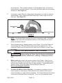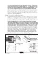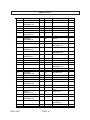
1
3-1/4” ELECTRIC PLANER
Model 91062
OPERATING INSTRUCTIONS
®
3491 Mission Oaks Blvd., Camarillo, CA 93011
Visit our Web site at: http://www.harborfreight.com
Copyright 2003 by Harbor Freight Tools®. All rights reserved. No portion of this
manual or any artwork contained herein may be reproduced in any shape or form
without the express written consent of Harbor Freight Tools.
For technical questions, please call 1-800-444-3353.
PRODUCT SPECIFICATIONS
Item
Electrical R equirem ents
M axim um Planing W idth
M axim um Planing D epth
D ust C hute D im ensions
Blade D im ensions
N um ber of Blades
Shoe Plate D im ensions
G uide D im ensions
W eight
D escription
120V / 60 H z / 5.5 AM Ps
16,500 R PM (N o Load) or 33,000 C uts Per M inute
Polarized, 2-Pole P ow er C ord Plug
Single P ole Pow er Sw itch w /Safety Lock Button
3-1/4”
U p To 1/16” Per P ass (Adjustable)
1-1/2” I.D . x 1-11/16” O .D .
7/32” W x 3-3/16” L x 3/64” H
2 (C om position: 65 M anganese Alloy S teel)
3-1/4” W x 6-1/2” L
3-1/4” W x 2-7/8” L
9.20 Pounds
SAVE THIS MANUAL
You will need this manual for the safety warnings and precautions, assembly,
operating, inspection, maintenance and cleaning procedures, parts list and assembly diagram. Keep your invoice with this manual. Write the invoice number
on the inside of the front cover. Keep this manual and invoice in a safe and dry
place for future reference.
GENERAL SAFETY RULES
WARNING!
READ AND UNDERSTAND ALL INSTRUCTIONS
Failure to follow all instructions listed below may result in
electric shock, fire, and/or serious injury.
SAVE THESE INSTRUCTIONS
WORK AREA
1.
Keep your work area clean and well lit. Cluttered benches and dark areas
invite accidents.
2.
Do not operate power tools in explosive atmospheres, such as in the
presence of flammable liquids, gases, or dust. Power tools create sparks
which may ignite the dust or fumes.
SKU 91062
PAGE 2
REV 02/04
3.
Keep bystanders, children, and visitors away while operating a power tool.
Distractions can cause you to lose control. Protect others in the work area from
debris such as chips and sparks. Provide barriers or shields as needed.
ELECTRICAL SAFETY
4.
Grounded tools must be plugged into an outlet properly installed and
grounded in accordance with all codes and ordinances. Never remove the
grounding prong or modify the plug in any way. Do not use any adapter
plugs. Check with a qualified electrician if you are in doubt as to whether
the outlet is properly grounded. If the tools should electrically malfunction or
break down, grounding provides a low resistance path to carry electricity away
from the user.
5.
Double insulated tools are equipped with a polarized plug (one blade is
wider than the other). This plug will fit in a polarized outlet only one way. If
the plug does not fit fully in the outlet, reverse the plug. If it still does not
fit, contact a qualified electrician to install a polarized outlet. Do not
change the plug in any way. Double insulation
eliminates the need for the
three wire grounded power cord and grounded power supply system.
6.
Avoid body contact with grounded surfaces such as pipes, radiators,
ranges, and refrigerators. There is an increased risk of electric shock if your
body is grounded.
7.
Do not expose power tools to rain or wet conditions. Water entering a power
tool will increase the risk of electric shock.
8.
Do not abuse the Power Cord. Never use the Power Cord to carry the tools
or pull the Plug from an outlet. Keep the Power Cord away from heat, oil,
sharp edges, or moving parts. Replace damaged Power Cords immediately. Damaged Power Cords increase the risk of electric shock.
9.
When operating a power tool outside, use an outdoor extension cord
marked “W-A” or “W”. These extension cords are rated for outdoor use, and
reduce the risk of electric shock.
SKU 91062
PAGE 3
PERSONAL SAFETY
10.
Stay alert. Watch what you are doing, and use common sense when operating a power tool. Do not use a power tool while tired or under the influence of drugs, alcohol, or medication. A moment of inattention while operating power tools may result in serious personal injury.
11.
Dress properly. Do not wear loose clothing or jewelry. Contain long hair.
Keep your hair, clothing, and gloves away from moving parts. Loose
clothes, jewelry, or long hair can be caught in moving parts.
12.
Avoid accidental starting. Be sure the Power Switch is off before plugging
in. Carrying power tools with your finger on the Power Switch, or plugging in
power tools with the Power Switch on, invites accidents.
13.
Remove adjusting keys or wrenches before turning the power tool on. A
wrench or a key that is left attached to a rotating part of the power tool may result
in personal injury.
14.
Do not overreach. Keep proper footing and balance at all times. Proper
footing and balance enables better control of the power tool in unexpected
situations.
TOOL USE AND CARE
15.
Do not force the tool. Use the correct tool for your application. The correct
tool will do the job better and safer at the rate for which it is designed.
16.
Do not use the power tool if the Power Switch does not turn it on or off.
Any tool that cannot be controlled with the Power Switch is dangerous and must
be replaced.
17.
Disconnect the Power Cord Plug from the power source before making any
adjustments, changing accessories, or storing the tool. Such preventive
safety measures reduce the risk of starting the tool accidentally.
18.
Store idle tools out of reach of children and other untrained persons. Tools
are dangerous in the hands of untrained users.
19.
Maintain tools with care. Keep cutting tools sharp and clean. Properly
maintained tools with a sharp cutting edge are less likely to bind and are easier
to control. Do not use a damaged tool. Tag damaged tools “Do not use” until
repaired.
SKU 91062
PAGE 4
20.
Check for misalignment or binding of moving parts, breakage of parts, and
any other condition that may affect the tool’s operation. If damaged, have
the tool serviced before using. Many accidents are caused by poorly maintained tools.
21.
Use only accessories that are recommended by the manufacturer for your
model. Accessories that may be suitable for one tool may become hazardous
when used on another tool.
SERVICE
22.
Tool service must be performed only by qualified repair personnel. Service
or maintenance performed by unqualified personnel could result in a risk of injury.
23.
When servicing a tool, use only identical replacement parts. Follow
instructions in the “Inspection, Maintenance, And Cleaning” section of this
manual. Use of unauthorized parts or failure to follow maintenance instructions
may create a risk of electric shock or injury.
GROUNDING
WARNING!
Improperly connecting the grounding wire can result in the risk of electric
shock. Check with a qualfified electrician if you are in doubt as to whether the
outlet is properly grounded. Do not modify the power cord plug provided with
the tool. Never remove the grounding prong from the plug. Do not use the
tool if the power cord or plug is damaged. If damaged, have it repaired by
a service facility before use. If the plug will not fit the outlet, have a proper
outlet installed by a qualified electrician.
GROUNDED TOOLS: TOOLS WITH THREE PRONG PLUGS
1.
Tools marked with “Grounding Required” have a three wire cord and three prong
grounding plug. The plug must be connected to a properly grounded outlet. If
the tool should electrically malfunction or break down, grounding provides a low
resistance path to carry electricity away from the user, reducing the risk of electric shock. (See Figure A, next page.)
2.
The grounding prong in the plug is connected through the green wire inside the
cord to the grounding system in the tool. The green wire in the cord must be the
only wire connected to the tool’s grounding system and must never be attached
to an electrically “live” terminal. (See Figure A.)
SKU 91062
PAGE 5
3.
Your tool must be plugged into an appropriate outlet, properly installed and
grounded in accordance with all codes and ordinances. The plug and outlet
should look like those in the following illustration. (See Figure A.)
FIGURE A
DOUBLE INSULATED TOOLS: TOOLS WITH TWO PRONG PLUGS
4.
Tools marked “Double Insulated” do not require grounding. They have a special
double insulation system which satisfies OSHA requirements and complies with
the applicable standards of Underwriters Laboratories, Inc., the Canadian
Standard Association, and the National Electrical Code. (See Figure B.)
5.
Double insulated tools may be used in either of the 120 volt outlets shown in the
following illustration. (See Figure B.)
FIGURE B
SKU 91062
PAGE 6
EXTENSION CORDS
1.
Grounded tools require a three wire extension cord. Double Insulated tools
can use either a two or three wire extension cord.
2.
As the distance from the supply outlet increases, you must use a heavier gauge
extension cord. Using extension cords with inadequately sized wire causes a
serious drop in voltage, resulting in loss of power and possible tool damage.
(See Figure C, next page.)
3.
The smaller the gauge number of the wire, the greater the capacity of the cord.
For example, a 14 gauge cord can carry a higher current than a 16 gauge cord.
(See Figure C.)
4.
If using more than one extension cord to make up the total length, make sure
each cord contains at least the minimum wire size required. (See Figure C.)
5.
If you are using one extension cord for more than one tool, add the nameplate
amperes and use the sum to determine the required minimum cord size.
(See Figure C.)
6.
If you are using an extension cord outdoors, make sure it is marked with the
suffix “W-A” (“W” in Canada) to indicate it is acceptable for outdoor use.
7.
Make sure your extension cord is properly wired and in good electrical condition.
Always replace a damaged extension cord or have it repaired by a qualified
electrician before using it.
8.
Protect your extension cords from sharp objects, excessive heat, and damp or
wet areas.
RECOMMENDED MINIMUM WIRE GAUGE FOR EXTENSION CORDS*
(120 VOLT)
NAMEPLATE
AMPERES
(At Full Load)
0 – 2.0
2.1 – 3.4
3.5 – 5.0
5.1 – 7.0
7.1 – 12.0
12.1 – 16.0
16.1 – 20.0
FIGURE C
SKU 91062
EXTENSION CORD LENGTH
25
50
75
Feet
Feet
Feet
18
18
18
18
18
18
18
18
16
18
16
14
18
14
12
14
12
10
12
10
* Based on limiting the line voltage drop
to five volts at 150% of the rated amperes.
PAGE 7
100
Feet
18
16
14
12
10
-
150
Feet
16
14
12
12
-
SYMBOLOGY
Double Insulated
Canadian Standards
Association
Underwriters
Laboratories, Inc.
V~
A
FIGURE D
no xxxx/min.
Volts Alternating Current
Amperes
No Load Revolutions
per Minute (RPM)
SPECIFIC SAFETY RULES
1.
Maintain a safe working environment. Keep the work area well lit. Make sure
there is adequate surrounding workspace. Always keep the work area free of
obstructions, grease, oil, trash, and other debris. Do not use the Planer in areas
near flammable chemicals, dusts, and vapors.
2.
Maintain labels and nameplates on the Planer. These carry important information. If unreadable or missing, contact Harbor Freight Tools for a replacement.
3.
Ground this product. To comply with the National Electric Code, and to provide
additional protection from the risk of electrical shock, this product should only be
connected to a 120 volt electrical outlet that is protected by a Ground Fault
Circuit Interrupter (GFCI).
4.
Never plug the Power Cord of this product into an electrical outlet while
standing on a wet or damp surface.
5.
To avoid electrical shock, do not pull or carry the Planer by its Power
Cord or pull the Power Cord around sharp corners or edges.
6.
Do not unplug the Planer by pulling on the Power Cord. Keep the Power
Cord away from heated surfaces.
7.
Avoid unintentional starting. Make sure you are prepared to begin work
before turning on the Planer.
SKU 91062
PAGE 8
8.
Use eye and breathing protection. Always wear ANSI approved safety impact
eye goggles and dust masks or a respirator when working with this product.
9.
Always turn off the Planer and unplug the unit from its electrical outlet
before performing any maintenance, or changing accessories.
10.
Never leave the Planer unattended when it is plugged into an electrical
outlet. Make sure to unplug it from its electrical outlet before leaving the area.
11.
Do not allow children to handle or play with this product.
12.
Store idle equipment. When not in use, tools and equipment should be stored
in a dry location to inhibit rust. Always lock up tools and equipment, and keep out
of reach of children.
13.
Do not use this product if under the influence of alcohol or drugs. Read
warning labels on prescriptions to determine if your judgement or reflexes are
impaired while taking drugs. If there is any doubt, do not attempt to use this
product.
14.
Industrial applications must follow OSHA requirements.
15.
Maintain this product with care. Keep this product clean and dry for better and
safer performance. Also, make sure to keep the Blades sharp.
16.
Maintenance: For your safety, service and maintenance should be performed
regularly by a qualified technician.
17.
Check for damaged parts. Before using this product, carefully check that it will
operate properly and perform its intended function. Check for damaged parts
and any other conditions that may affect the operation of this product. Replace
or repair damaged or worn parts immediately.
18.
Do not use the Planer if it has been dropped, damaged, left outdoors, or
immersed in liquid.
19.
To avoid electrical shock, do not handle the Power Cord Plug or Planer with
wet hands.
20.
Keep all guards in place and in working order.
21.
Remove all adjusting wrenches from the Planer before turning it on.
22.
Allow the Blades to spin up to full speed before feeding them into the
workpiece. When turning off the Planer, allow the Blades to spin down and stop
SKU 91062
PAGE 9
on their own. Do not press against the Knives to stop them. Always keep hands
and fingers clear of spinning Blades.
23.
Do not force the Blades into the workpiece being cut. Apply moderate pressure, allowing the Blades to cut without being forced.
24.
Never attempt to remove material stuck in the moving parts of the Planer
while it is plugged in and running.
25.
Whenever possible, use clamps, a vise, or other safe, practical ways to
hold and support the workpiece.
26.
Always grip a power tool firmly with both hands when using.
27.
Always disconnect the tool from its electric outlet before performing any
services or maintenance such as leaving the work area, moving the tool from
one location to another, cleaning wood chips and sawdust from the unit, etc.
28.
Replacement parts and accessories: When servicing, use only identical replacement parts. Only use accessories intended for use with this product.
29.
Use the right tool or attachment for the right job. Do not attempt to force a
small tool or attachment to do the work of a larger industrial tool or attachment.
There are certain applications for which this product was designed. It will do the
job better and more safely at the rate for which it was intended. Do not modify
this product, and do not use this product for a purpose for which it was not intended.
30.
WARNING! People with pacemakers should consult their physician(s)
before using this product. Operation of electrical equipment in close proximity to
a heart pacemaker could cause interference or failure of the pacemaker.
WARNING! Some dust created by power sanding, planing, sawing, grinding, drilling, and other construction activities contain chemicals known (to the
State of California) to cause cancer, birth defects, or other reproductive harm.
Some examples of these chemicals are; lead from lead-based paints, crystalline
silica from bricks and cement or other masonry products, and arsenic and chromium from chemically treated lumber. Your risks from these exposures varies,
depending on how often you do this type of work. To reduce your exposure to
these chemicals, work in a well ventilated area, and work with approved safety
equipment, such as those dust masks and respirators that are specially designed
to filter out microscopic particles.
(California Health & Safety Code 25249.5, et seq.)
31.
SKU 91062
WARNING! The warnings, precautions, and instructions discussed in this
PAGE 10
manual cannot cover all possible conditions and situations that may occur. The
operator must understand that common sense and caution are factors which
cannot be built into this product, but must be supplied by the operator.
UNPACKING
When unpacking, check to make sure all the parts shown on the Parts List on page 16
are included. If any parts are missing or broken, please call Harbor Freight Tools at the
number shown on the cover of this manual as soon as possible.
OPERATING INSTRUCTIONS
NOTE: For additional information regarding the parts mentioned in the following pages,
refer to the Assembly Diagram on page 17.
The Power Switch:
1.
The Trigger (16) of the Planer features a Safety Lock Button (17) to ensure
against accidental starting of the tool. To start the tool, depress the Safety Lock
Button. Squeeze the Trigger, and release pressure on the Safety Lock Button.
To stop the tool, release pressure on the Trigger.
(See Figure E.)
SAFETY LOCK BUTTON (17)
TRIGGER (16)
DEPTH KNOB (48)
DIAL (51)
FIGURE E
The Depth Knob:
1.
The Planer may be adjusted to cut to a depth of up to 1/16” per pass along
the wood stock. To increase the depth of cut, turn the Depth Knob (48) clockwise. To decrease the depth of cut, turn the Depth Knob counterclockwise.
Always return the Depth Knob to read 0 on the Dial (51) when finished cutting.
NOTE: Use a deeper cut, but never to exceed 1/16”, for a rough cut piece of
wood stock. Once planed smooth, it is recommended to take a number of
smaller cuts to acquire the desired depth. (See Figure E.)
SKU 91062
PAGE 11
The Guide:
1.
The Guide (64) can be used to adjust the width of cut, support the Planer, and
keep the Planer from drifting away from the cut line (i.e., the edge of a door).
The Guide may be attached either to the right side of the Planer or on its left
side. To do so, position the Planer on the wood stock that is to be cut. Loosen
the Screw (47) located at the front of the Planer. Insert the Guide into the mounting hole located on either side toward the front of the Planer. Slide the Guide in
until it contacts the edge of the wood stock. Then, lock the Guide in place by
retightening the Screw. (See Figure F.)
FIGURE F
SCREW
(47)
SCREW
(47)
GUIDE
(64)
GUIDE
(64)
WOOD STOCK
WOOD STOCK
To Make A Cut:
1.
CAUTION! Make sure the Trigger (16) is in its “OFF” position, and that the
Planer is unplugged from its 120 volt, grounded, electrical outlet. Then, make any
necessary adjustments to the cutting depth and cutting width of the Planer.
(See Figures E, and F.)
2.
Whenever possible, use clamps, a vise, or other safe, practical ways to hold and
support the wood stock.
3.
While standing to the side of the wood stock, hold the Planer firmly with one hand
on the handle portion of the Housing (15, 45), and the other hand on the Depth
Knob (48).
4.
Set the Front Base Plate (54) of the Planer on the front edge of the wood stock.
Then, depress the Safety Lock Button (17) and squeeze the Trigger (16) to start
the Planer. IMPORTANT: Do not allow the Blades (57) of the Planer to contact
the wood stock until the Blades are spinning at full speed.
(See Figure G, next page.)
5.
While placing pressure on the Front Base Plate (54) to control the depth of cut,
and while placing pressure on the Guide (64) against the wood stock to control
the width of cut, feed the Planer slowly until the Rear Base Plate (61) contacts
SKU 91062
PAGE 12
the wood stock. Then, transfer pressure to the Rear Base Plate, and continue
planing slowly to the end of the cut. Do not pull the Planer back over the surface
already cut. (See Figure G.)
6.
If necessary, repeat Step #5, using progressively deeper cuts until you near the
desired depth. Then, readjust the Depth Knob (48) to make a light cut for the
final pass. (See Figure G.)
DEPTH KNOB
(48)
REAR BASE PLATE
(61)
FRONT BASE PLATE
(54)
FIGURE G
7.
NOTE: The Planer’s Motor may stall if the tool is improperly used. If the Motor
begins to stall, reduce the feed speed at which you are making the cut and/or
reduce the depth of the cut.
8.
When finished planing, release pressure on the Trigger (16) and the Planer will
automatically stop. Wait until Planer blade comes to a complete stop. Then
unplug the Planer from its electrical outlet, and store the Planer in a safe, clean,
dry location.
INSPECTION, MAINTENANCE, AND CLEANING
1.
WARNING! Always unplug the Planer from its electrical outlet before
performing any inspection, maintenance, cleaning, or changing accessories.
2.
Before each use, inspect the general condition of the Planer. Check for misalignment or binding of moving parts, cracked or broken parts, damaged wiring,
and any other condition that may affect its safe operation. If abnormal noise or
vibration occurs, have the problem corrected before further use.
Do not use damaged equipment.
3.
To replace the Motor Carbon Brushes: It may become necessary at sometime to replace or clean the two Carbon Brushes (36) when the Motor performance decreases, or stops working completely. The Carbon Brushes are located
on the side of the Right Motor Housing (45). To do so, use a standard screw-
SKU 91062
PAGE 13
driver (not included) to remove the two Carbon Brush Caps (35). Then, remove
the two Carbon Brushes from the Brush Holders (38). If a Carbon Brush is worn
down more than 1/2 of its original length, replace both Carbon Brushes. If, however, the Carbon Brushes are just dirty they may be cleaned by rubbing them
with a pencil eraser. When installing the Carbon Brushes, make sure the carbon
portion of the Carbon Brushes contact the Motor Armature, and that the springs
face away from the Motor. Also, make sure the springs operate freely. After
cleaning or replacement, replace the Carbon Brush Caps with a screwdriver and
tighten firmly. (See Assy. Diagram.)
Caution: Use caution as blades are very sharp.
4.
To reverse or replace the Blades: The Planer is equipped with two reversible
Blades (57). Do not attempt to sharpen the Blades. Always reverse or replace
the Blades as a set in order to avoid an imbalance of the Blade Holder (59). To
reverse or replace the Blades, use an open end wrench to loosen the three Hex
Head Screws (60) that secure the Blades, Press Blade Plate (56), and Blade
Holder to the Blade Shaft (63). Slide the Blades lengthwise out of the Blade
Shaft, using a piece of wood to avoid cuts to your fingers. Once the Blades have
been removed, clean the Blades, Press Blade Plate, Blade Holder, and the Blade
Shaft thoroughly before installing the reversed or new Blades to allow for a more
accurate Blade setting. When installing the reversed or new Blades, it is important that they be properly adjusted so that they align evenly with the Front Base
Plate (54) and Rear Base Plate (61). Slide the Blades lengthwise into the Blade
Shaft, using a piece of wood. Place a straight edge or piece of wood along the
side surfaces of the Front Base Plate and Rear Base Plate. Then, slide the
Blades against the straight edge or piece of wood. Finally, use an open end
wrench to retighten the three Hex Head Screws that secure the Blades, Press
Blade Plate, and Blade Holder to the Blade Shaft. (See Figure H.)
(BOTTOM VIEW)
BLADE (57)
HEX HEAD SCREW (60)
BLADE HOLDER (59)
PRESS BLADE PLATE (56)
BLADE SHAFT (63)
HEX HEAD SCREW
(60)
FIGURE H
SKU 91062
PAGE 14
ALIGN
BLADES
USING
PIECE
OF WOOD
(BOTTOM VIEW)
5.
To clean the outer body of the Planer, use a shop vacuum or compressed air.
Do not immerse any part of this Planer in liquid.
PLEASE READ THE FOLLOWING CAREFULLY
THE MANUFACTURER AND/OR DISTRIBUTOR HAS PROVIDED THE PARTS LIST AND
ASSEMBLY DIAGRAM IN THIS MANUAL AS A REFERENCE TOOL ONLY. NEITHER THE
MANUFACTURER OR DISTRIBUTOR MAKES ANY REPRESENTATION OR WARRANTY OF
ANY KIND TO THE BUYER THAT HE OR SHE IS QUALIFIED TO MAKE ANY REPAIRS TO THE
PRODUCT, OR THAT HE OR SHE IS QUALIFIED TO REPLACE ANY PARTS OF THE PRODUCT.
IN FACT, THE MANUFACTUER AND/OR DISTRIBUTOR EXPRESSLY STATES THAT ALL
REPAIRS AND PARTS REPLACEMENTS SHOULD BE UNDERTAKEN BY CERTIFIED AND
LICENSED TECHNICIANS, AND NOT BY THE BUYER. THE BUYER ASSUMES ALL RISK AND
LIABILITY ARISING OUT OF HIS OR HER REPAIRS TO THE ORIGINAL PRODUCT OR
REPLACEMENT PARTS THERETO, OR ARISING OUT OF HIS OR HER INSTALLATION OF
REPLACEMENT PARTS THERETO.
SKU 91062
PAGE 15
PARTS LIST
Part #
1
2
3
4
5
6
7
8
9
10
11
12
13
14
15
16
17
18
19
20
21
22
23
24
25
26
27
Description
Name Plate
Tap Screw
(8SEABB04-18)
Cover
Belt
Bearing Sleeve
Bearing
(8SG6000Z-01)
Press Board
Tap Screw
(8SEABB04-8)
Large Belt Wheel
Small Belt Wheel
Qty.
1
3
Part #
33
34
Description
Screw Arbor
Spring
Qty.
1
1
1
1
1
1
35
36
37
38
Carbon Brush Cap
Carbon Brush
Carbon Brush Sleeve
Carbon Brush Holder
2
2
2
2
1
2
39
40
Rear Cover
Stopper
1
1
1
1
41
42
1
3
Tap Screw
(8SGABB04-8)
Press Board
2
43
Cover
Tap Screw
(8SEABB04-18)
Label
1
44
9
Bearing
(8SG608Z-01)
Bearing Sleeve
Left Motor Housing
Trigger
Safety Lock Button
1
45
Tap Screw
(8SEABB04-18)
Right Motor Housing
1
1
1
1
46
47
48
49
1
1
2
Power Switch
Handle Cover
Tap Screw
(8SEABB04-18)
Power Cord
Spring
Stator
Tap Screw
(8SEABB04-60)
Armature
Wind Shield
1
1
4
1
1
1
50
51
52
Nut (M5)
Screw
Depth Knob
Tap Screw
(8SEABB04-14)
Plug Cock
Dial
Adjustable Nut
1
1
1
2
53
54
55
56
Adjustable Spring
Front Base Plate
Cylinder Pin
Press Blade Plate
1
1
1
2
1
1
57
58
2
4
1
59
Blade
Socket Head Cap
Screw
Blade Holder
1
1
1
1
2
60
61
Hex Head Screw
Rear Base Plate
6
1
30
Bearing
(8SG608G-01)
Bearing Sleeve
Tap Screw
(8SEABB04-14)
Press Cord Board
1
62
1
31
32
Press Cord Shield
Screw Arbor
1
1
63
64
Bearing
(8SG608Z-01)
Blade Shaft
Guide (Not Shown)
28
29
SKU 91062
PAGE 16
2
1
1
17
16
18
ASSEMBLY DIAGRAM
68: GUIDE NOT SHOWN.
NOTE: Some parts are listed and shown for illustration purposes only, and are not
available individually as replacement parts.
SKU 91062
PAGE 17