1
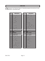
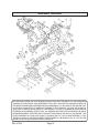
PROFESSIONAL
9” CIRCULAR SAW W/BLADE
47613
ASSEMBLY AND OPERATING INSTRUCTIONS
Diagrams within this manual may not be drawn proportionally.
Due to continuing improvements, actual product may differ slightly from the product described herein.
Distributed exclusively by Harbor Freight Tools®.
3491 Mission Oaks Blvd., Camarillo, CA 93011
Visit our website at: http://www.harborfreight.com
Read this material before using this product.
Failure to do so can result in serious injury.
Save this manual.
Copyright© 2003 by Harbor Freight Tools®. All rights reserved. No portion of this
manual or any artwork contained herein may be reproduced in any shape or form
without the express written consent of Harbor Freight Tools.
For technical questions or replacement parts, please call 1-800-444-3353.
PRODUCT SPECIFICATIONS
Power Consumption
Motor
Line Cord
Saw Blade
Cutting Capacity
Arbor
Accessories
Features
Weight
Overall Dimensions
120 VAC, 60 Hz, 1380 watts, 16 peak amps
4000 RPM, gear driven
16 AWG x 2, UL listed, two-prong polarized
plug
9 inches; 60 tooth carbide tipped; spindle lock
90° = 3.3 inches; 45°= 2.28 inches
5/8 inch
Dust Bag; one set of extra motor brushes
Automatic guard return; Side handle
15.6 lbs.
14-1/2 x 10 x 7-1/2 inches
SAVE THIS MANUAL
You will need this manual for the safety warnings and precautions, assembly, operating, inspection, maintenance and cleaning procedures, parts list and assembly diagram. Keep your invoice with this manual. Write the invoice number on the
inside of the front cover. Keep this manual and invoice in a safe and dry place for
future reference.
GENERAL SAFETY RULES
WARNING!
READ AND UNDERSTAND ALL INSTRUCTIONS
Failure to follow all instructions listed below may result in
electric shock, fire, and/or serious injury.
SAVE THESE INSTRUCTIONS
WORK AREA
1.
Keep your work area clean and well lit. Cluttered benches and dark areas invite accidents.
2.
Do not operate power tools in explosive atmospheres, such as in the presence of flammable liquids, gases, or dust. Power tools create sparks which may ignite the dust or fumes.
3.
Keep bystanders, children, and visitors away while operating a power tool.
Distractions can cause you to lose control. Protect others in the work area from debris such as chips and sparks. Provide barriers or shields as needed.
SKU 47613
Page 2
REV 07l
ELECTRICAL SAFETY
4.
Grounded tools must be plugged into an outlet properly installed and grounded in accordance with all codes and ordinances. Never remove the grounding prong or modify the plug in any way. Do not use any adapter plugs. Check with a qualified electrician if you are in doubt as to whether the outlet is properly grounded. If the tools should electrically malfunction or
break down, grounding provides a low resistance path to carry electricity away from the user.
5.
Double insulated tools are equipped with a polarized plug (one blade is
wider than the other). This plug will fit in a polarized outlet only one way. If the plug does not fit fully in the outlet, reverse the plug. If it still does not fit, contact a qualified electrician to install a polarized outlet. Do not
change the plug in any way. Double insulation
eliminates the need for the three wire grounded power cord and grounded power supply system.
6.
Avoid body contact with grounded surfaces such as pipes, radiators, ranges, and refrigerators. There is an increased risk of electric shock if your body is grounded.
7.
Do not expose power tools to rain or wet conditions. Water entering a power tool will increase the risk of electric shock.
8.
Do not abuse the Power Cord. Never use the Power Cord to carry the tools or pull the Plug from an outlet. Keep the Power Cord away from heat, oil,
sharp edges, or moving parts. Replace damaged Power Cords immediately.
Damaged Power Cords increase the risk of electric shock.
9.
When operating a power tool outside, use an outdoor extension cord marked “W-A” or “W”. These extension cords are rated for outdoor use, and reduce the risk of electric shock.
PERSONAL SAFETY
10.
Stay alert. Watch what you are doing, and use common sense when
operating a power tool. Do not use a power tool while tired or under the
influence of drugs, alcohol, or medication. A moment of inattention while
perating power tools may result in serious personal injury.
11.
Dress properly. Do not wear loose clothing or jewelry. Contain long hair.
Keep your hair, clothing, and gloves away from moving parts. Loose clothes, jewelry, or long hair can be caught in moving parts.
SKU 47613
Page 3
12.
Avoid accidental starting. Be sure the Power Switch is off before plugging in. Carrying power tools with your finger on the Power Switch, or plugging in power tools with the Power Switch on, invites accidents.
13.
Remove adjusting keys or wrenches before turning the power tool on. A wrench or a key that is left attached to a rotating part of the power tool may result in personal injury.
14.
Do not overreach. Keep proper footing and balance at all times. Proper footing and balance enables better control of the power tool in unexpected
situations.
15.
Use safety equipment. Always wear eye protection. Dust mask, non-skid safety shoes, hard hat, or hearing protection must be used for appropriate
conditions.
TOOL USE AND CARE
16.
Use clamps (not included) or other practical ways to secure and support the workpiece to a stable platform. Holding the work by hand or against your body is unstable and may lead to loss of control.
17.
Do not force the tool. Use the correct tool for your application. The correct tool will do the job better and safer at the rate for which it is designed.
18.
Do not use the power tool if the Power Switch does not turn it on or off. Any tool that cannot be controlled with the Power Switch is dangerous and must be replaced.
19.
Disconnect the Power Cord Plug from the power source before making any
adjustments, changing accessories, or storing the tool. Such preventive safety measures reduce the risk of starting the tool accidentally.
20.
Store idle tools out of reach of children and other untrained persons. Tools are dangerous in the hands of untrained users.
21.
Maintain tools with care. Keep cutting tools sharp and clean. Properly maintained tools with a sharp cutting edge are less likely to bind and are easier to control. Do not use a damaged tool. Tag damaged tools “Do not use” until repaired.
22. Check for misalignment or binding of moving parts, breakage of parts, and any other condition that may affect the tool’s operation. If damaged, have
the tool serviced before using. Many accidents are caused by poorly
maintained tools.
SKU 47613
Page 4
23.
Use only accessories that are recommended by the manufacturer for your
model. Accessories that may be suitable for one tool may become hazardous when used on another tool.
SERVICE
24.
Tool service must be performed only by qualified repair personnel. Service or maintenance performed by unqualified personnel could result in a risk of injury.
25.
When servicing a tool, use only identical replacement parts. Follow instructions in the “Inspection, Maintenance, And Cleaning” section of this manual. Use of unauthorized parts or failure to follow maintenance instructions may create a risk of electric shock or injury.
SPECIFIC SAFETY RULES
1.
Maintain labels and nameplates on the Circular Saw. These carry impor-
tant information. If unreadable or missing, contact Harbor Freight Tools for a replacement.
2.
Always wear safety impact eye goggles and heavy work gloves when using the Circular Saw. Using personal safety devices reduce the risk for injury. Safety impact eye goggles and heavy work gloves are available from Harbor Freight Tools.
3.
Maintain a safe working environment. Keep the work area well lit. Make sure
there is adequate surrounding workspace. Always keep the work area free of
obstructions, grease, oil, trash, and other debris. Do not use a power tool in areas
near flammable chemicals, dusts, and vapors. Do not use this product in a damp
or wet location.
4.
When using a hand-held power tool, always maintain a firm grip on the tool
with both hands to resist starting torque.
5.
Always keep the extension cord away from moving parts on the tool.
6.
Avoid unintentional starting. Make sure you are prepared to begin work before turning on the Circular Saw.
7.
Do not force the Circular Saw. This tool will do the work better and safer at the speed and capacity for which it was designed.
8.
Never leave the Circular Saw unattended when it is plugged into an electrical outlet. Turn off the tool, and unplug it from its electrical outlet before leaving.
9.
Always unplug the Circular Saw from its electrical outlet before performing
and inspection, maintenance, or cleaning procedures.
10. Secure work. Use clamps or a vise to hold work. Do not use hands to secure.
SKU 47613
Page 5
11. Never touch moving parts. Never place your hands, fingers or other body parts
near the tool’s moving parts.
12. Never operate without automatic guard return in place. Do not disable blade
guard when cutting.
13. Guard against kickback. Kickback occurs when the saw stalls and is driven
backwards toward the operator. When this happens, release trigger switch
immediately.
14. Unplug Circular Saw Line Cord before making adjustments.
15. When operating, keep Line Cord away from the cutting area.
16. Never operate the Circular Saw with its saw blade facing upward.
17. After cutting, wait for the saw blade to stop turning before setting the unit
down.
18. Only use a 9” saw blade on this Circular Saw. The blade must have a speed rating
of 4,000 RPM or greater.
19.
WARNING! Some dust created by power sanding, sawing, grinding,
drilling, and other construction activities, contain chemicals known (to the State
of California) to cause cancer, birth defects or other reproductive harm. Some
examples of these chemicals are: lead from lead-based paints, crystalline silica
from bricks and cement or other masonry products, arsenic and chromium from
chemically treated lumber. Your risk from these exposures varies, depending on
how often you do this type of work. To reduce your exposure to these chemicals:
work in a well ventilated area, and work with approved safety equipment, such as
those dust masks that are specially designed to filter out microscopic particles.
(California Health & Safety Code 25249.5, et seq.)
20.
WARNING! People with pacemakers should consult their physician(s) before
using this product. Operation of electrical equipment in close proximity to a heart
pacemaker could cause interference or failure of the pacemaker.
SKU 47613
Page 6
REV 07l
GROUNDING
WARNING!
Improperly connecting the grounding wire can result in the risk of electric
shock. Check with a qualfified electrician if you are in doubt as to whether the
outlet is properly grounded. Do not modify the power cord plug provided with
the tool. Never remove the grounding prong from the plug. Do not use the
tool if the power cord or plug is damaged. If damaged, have it repaired by
a service facility before use. If the plug will not fit the outlet, have a proper
outlet installed by a qualified electrician.
GROUNDED TOOLS: TOOLS WITH THREE PRONG PLUGS
1.
Tools marked with “Grounding Required” have a three wire cord and three prong grounding plug. The plug must be connected to a properly grounded outlet. If the tool should electrically malfunction or break down, grounding provides a low resistance path to carry electricity away from the user, reducing the risk of elec-
tric shock. (See Figure A.)
2.
The grounding prong in the plug is connected through the green wire inside the cord to the grounding system in the tool. The green wire in the cord must be the only wire connected to the tool’s grounding system and must never be attached to an electrically “live” terminal. (See Figure A.)
3.
Your tool must be plugged into an appropriate outlet, properly installed and grounded in accordance with all codes and ordinances. The plug and outlet should look like those in the following illustration. (See Figure A.)
FIGURE A
SKU 47613
Page 7
DOUBLE INSULATED TOOLS: TOOLS WITH TWO PRONG PLUGS
4.
Tools marked “Double Insulated” do not require grounding. They have a special double insulation system which satisfies OSHA requirements and complies with the applicable standards of Underwriters Laboratories, Inc., the Canadian
Standard Association, and the National Electrical Code. (See Figure B.)
5.
Double insulated tools may be used in either of the 120 volt outlets shown in the following illustration. (See Figure B.)
FIGURE B
EXTENSION CORDS
1.
Grounded tools require a three wire extension cord. Double Insulated tools can use either a two or three wire extension cord.
2.
As the distance from the supply outlet increases, you must use a heavier gauge extension cord. Using extension cords with inadequately sized wire causes a serious drop in voltage, resulting in loss of power and possible tool damage. (See Figure C, next page.)
3.
The smaller the gauge number of the wire, the greater the capacity of the cord. For example, a 14 gauge cord can carry a higher current than a 16 gauge cord. (See Figure C.)
4.
When using more than one extension cord to make up the total length, make sure each cord contains at least the minimum wire size required.
(See Figure C.)
5.
If you are using one extension cord for more than one tool, add the nameplate
amperes and use the sum to determine the required minimum cord size.
(See Figure C.)
SKU 47613
Page 8
6.
If you are using an extension cord outdoors, make sure it is marked with the suffix “W-A” (“W” in Canada) to indicate it is acceptable for outdoor use.
7.
Make sure your extension cord is properly wired and in good electrical condition.
Always replace a damaged extension cord or have it repaired by a qualified electrician before using it.
8.
Protect your extension cords from sharp objects, excessive heat, and damp or
wet areas.
RECOMMENDED MINIMUM WIRE GAUGE FOR EXTENSION CORDS*
(120 VOLT)
NAMEPLATE
EXTENSION CORD LENGTH
AMPERES
(At Full Load)
25
50
75
100
Feet
Feet
Feet
Feet
0 – 2.0
18
18
18
18
2.1 – 3.4
18
18
18
16
3.5 – 5.0
18
18
16
14
5.1 – 7.0
18
16
14
12
7.1 – 12.0
18
14
12
10
12.1 – 16.0
14
12
10
16.1 – 20.0
12
10
* Based on limiting the line voltage drop
FIGURE C
to five volts at 150% of the rated amperes.
SYMBOLOGY
Double Insulated
Canadian Standards
Association
Underwriters
Laboratories, Inc.
V~
A
no
xxxx/min.
SKU 47613
Volts Alternating Current
Amperes
No Load Revolutions
per Minute (RPM)
Page 9
150
Feet
16
14
12
10
-
UNPACKING
When unpacking, check to make sure all the parts shown in Figure C are included. If any
parts are missing or broken, please call Harbor Freight Tools at the
number shown on the cover of this manual as soon as possible.
Side Handle
Saw Blade
Saw Blade
Removal Wrench
Rip Guide
Figure C
ASSEMBLY AND OPERATING INSTRUCTIONS
NOTE: For additional information regarding the parts listed in the following pages, refer
to the Assembly Diagram on the last page page of this manual.
CAUTION: Always make sure the Power Cord Circular saw is unplugged from its
electrical outlet prior to making any adjustments to the tool.
Adjusting The Saw Prior to Cutting
1.
Screw the Side Handle (401) into the Circular Saw housing.
2.
To adjust the angle of blade from 0 to 45 degrees, loosen Wing Nut (60) and
move Base Assy. (52) down, observing the degrees indicated on the angle plate.
Tighten Wing Nut (60).
See Figures D and E on the next page.
3.
To adjust the depth of the cut, loosen Lock Handle (55) and move Base Assy. (52)
down (or up) while observing the amount of saw blade exposed under base plate.
Tighten Lock Handle (55).
SKU 47613
Page 10
Side Handle (401)
Brush Cap (30)
Wing Nut (60)
Wing Bolt (58)
Base Assy. (52)
Figure D
Figure E
Lock Handle (55)
Prepare Material Before Cutting
1.
Support large panels to minimize risk of blade pinching and saw kickback.
2.
Use the supplied Rip Guide (402) when ripping material by sliding it into the Base
Assy. and tightening Wing Bold (58). See Figures F and G below.
3.
Securely clamp material to be cut to work bench.
4.
Make sure saw does not cut into supports or workbench.
5.
Use the appropriate type of blade for the material you are cutting.
Figure F
Figure G
SKU 47613
Page 11
Cutting
Caution: Verify that saw blade is securely tightened and both angle and height
adjusting knobs are tight.
1.
If desired for a straight cut, slide the Rip Guide (402) into the side of the Circular
Saw and tighten with Wing Bolt (58), or clamp a straight edge to the material to
guide the saw on a straight path.
2.
Place the saw Base Assy. on the material to be cut. Align the front notch (right
edge aligns with saw blade) on the cut line.
3.
Hold the Circular Saw by both handles.Always keep hands and fingers away from
the Saw Blade.
4.
Squeeze the trigger Switch (12) with the index finger. Do this before the saw blade
touches the material.
5.
With the saw at full speed, move the saw slowly forward to complete the cut.
6.
When the cut in complete, release the trigger Switch. Do not set the saw down
until the blade stops turning.
INSPECTION, MAINTENANCE, AND CLEANING
1.
WARNING! Make sure the Power Switch (part #12) of the Circular Saw is in
its “OFF” position and that the tool is unplugged from its electrical outlet before
performing any inspection, maintenance, or cleaning procedures.
2.
BEFORE EACH USE, inspect the general condition of the Circular Saw. Check
for loose screws, misalignment or binding of moving parts, cracked or broken
parts, damaged electrical wiring, and any other condition that may affect its safe
operation. If abnormal noise or vibration occurs, have the problem corrected before further use. Do not use damaged equipment.
3.
Before remounting the saw blade, remove all sawdust that has accumulated
around the safety guard.
4.
Regularly inspect and tighten all mounting screws and knobs.
5.
Keep saw blades clean and sharp. Sharp blades minimize stalling and kickback.
6.
Keep guards in good working order.
7.
Keep motor air vent clean of dust and debris. Vacuum periodically.
8.
If the tool is not operating normally, making unusual noises, or appears defective,
stop using it immediately and get it repaired.
9.
Clean tool with a damp cloth and light detergent. Do not use solvents as they can
damage and crack the plastic parts.
SKU 47613
Page 12
Replacing the Carbon Brushes
1.
Unscrew the Brush Caps (30).
2.
Pull out the Carbon Brush (29) from each side of the motor and examine them.
If they are worn more than half way down, replace them. It could be that they are
simply dirty. They can be cleaned using an ink eraser.
3.
Replace the Brush Caps.
Installing a New Saw Blade
1.
Always use 9 inch saw blades. The saw blade speed rating must be at least 4,000
RPM.
Refer to the following table for saw blade applications and types.
APPLICATION
BLADE
DESCRIPTION
No. OF TEETH TYPE OF CUT
Fine Trim Molding
Precision Trim
Carbide
60 ~ 100
Very smooth,
splinter free
Trim, Framing,
Pressure Treated
Decking
Combination,
multi-purpose
32 ~ 60
Smooth, fast
cut
Aluminum
Non-ferrous metal
cutting
60 ~ 80
----
2.
Unplug the Circular Saw Power Cord from the electrical outlet.
3.
Raise the blade Guard as far as possible.
4.
Hold the blade Guard up and press the Spindle Lock Button with one hand.
Rotate the Saw Blade until the Spindle Lock catches and the blade stops.
5.
Using the supplied Blade Wrench in the other hand, loosen (clockwise) the lefthand threaded Blade Screw. Remove the Blade Screw, Outer Clamp Washer, then
the Saw Blade.
6.
Place the new Saw Blade over the arbor hole.
The Saw Blade teeth at the bottom of the saw blade should be pointing toward the
back of the saw.
7.
Place the Outer Clamp Washer over the arbor hole, then insert the Blade Screw.
8.
Press the Spindle Lock Button with one hand, and tighten the Blade Screw
(counterclockwise) using the Blade Wrench.
SKU 47613
Page 13
REV 07l
Parts List
NOTE: Some parts are listed and shown for illustration purposes only, and are not available individually as replacement parts.
Part
#
1
3
4
6
7
8
9
10
12
13
14
15
16
17
18
19
21
22
24
25
26
27
28
29
30
31
32
33
34
35
36
37
Description
Screw
Housing Assy.
Screw
Name Plate
Cord Support
Cord
Cord Clip
Tapping Screw
Switch
Screw
Screw
Handle Cover
Nut
Rubber Pole
Ball Bearing
Fan Baffle
Fan
Armature
Ball Bearing
Rubber Pole
Stator
Gear Cover Assy.
Lock Lever
Carbon Brush
Brush Cap
Rubber Cushion
Screw
Screw, Socket, Hex
Screw, Socket, Hex
Needle Bearing
Ex Ret. Ring
Gear
SKU 47613
Part
#
38
39
40
41
42
43
44
45
46
47
48
49
50
51
52
53
54
55
56
57
58
59
60
61
62
63
64
65
66
67
401
402
Page 14
Description
Int. Ret. Ring
Ball Bearing
Key
Spindle
Bearing Housing
Screw
Screw
Spring
Safety Cover
Arbor Bolt
Outer Blade Flange
Inner Blade Flange
Ext. Ret. Ring
Bolt, Square
Base Assy.
Flat Washer
Nut
Lock Handle
Screw
Bolt, Square
Wing Bolt
Screw
Wing Nut
Spring Washer
Flat Washer
Flat Washer
Spring Washer
Nut
Dust Chute
Screw
Side Handle
Rip Guide
ASSEMBLY DIAGRAM
THE MANUFACTURER AND/OR DISTRIBUTOR HAS PROVIDED THE PARTS LIST AND ASSEMBLY
DIAGRAM IN THIS MANUAL AS A REFERENCE TOOL ONLY. NEITHER THE MANUFACTURER OR
DISTRIBUTOR MAKES ANY REPRESENTATION OR WARRANTY OF ANY KIND TO THE BUYER THAT
HE OR SHE IS QUALIFIED TO MAKE ANY REPAIRS TO THE PRODUCT, OR THAT HE OR SHE IS
QUALIFIED TO REPLACE ANY PARTS OF THE PRODUCT. IN FACT, THE MANUFACTUER AND/OR
DISTRIBUTOR EXPRESSLY STATES THAT ALL REPAIRS AND PARTS REPLACEMENTS SHOULD
BE UNDERTAKEN BY CERTIFIED AND LICENSED TECHNICIANS, AND NOT BY THE BUYER. THE
BUYER ASSUMES ALL RISK AND LIABILITY ARISING OUT OF HIS OR HER REPAIRS TO THE
ORIGINAL PRODUCT OR REPLACEMENT PARTS THERETO, OR ARISING OUT OF HIS OR HER
INSTALLATION OF REPLACEMENT PARTS THERETO.
SKU 47613
Page 15
Limited 1 Year warranty
Harbor Freight Tools Co. makes every effort to assure that its products meet high
quality and durability standards, and warrants to the original purchaser that this product is
free from defects in materials and workmanship for the period of one year from the date of
purchase (90 days if used by a professional contractor or if used as rental equipment). This
warranty does not apply to damage due directly or indirectly, to misuse, abuse, negligence
or accidents, repairs or alterations outside our facilities, normal wear and tear, or to lack
of maintenance. We shall in no event be liable for death, injuries to persons or property,
or for incidental, contingent, special or consequential damages arising from the use of our
product. Some states do not allow the exclusion or limitation of incidental or consequential
damages, so the above limitation of exclusion may not apply to you. This warranty is
expressly in lieu of all other warranties, express or implied, including the warranties of merchantability and fitness.
To take advantage of this warranty, the product or part must be returned to us with
transportation charges prepaid. Proof of purchase date and an explanation of the complaint must accompany the merchandise. If our inspection verifies the defect, we will either
repair or replace the product at our election or we may elect to refund the purchase price
if we cannot readily and quickly provide you with a replacement. We will return repaired
products at our expense, but if we determine there is no defect, or that the defect resulted
from causes not within the scope of our warranty, then you must bear the cost of returning
the product.
This warranty gives you specific legal rights and you may also have other rights
which vary from state to state.
3491 Mission Oaks Blvd. • PO Box 6009 • Camarillo, CA 93011 • (800) 444-3353
SKU 47613
Page 15 REV 08j