1
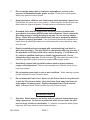
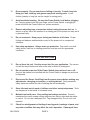
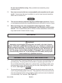
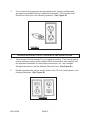
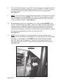
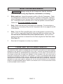
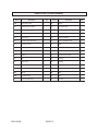
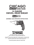
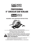
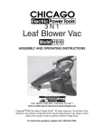
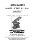
®
COMPRESSOR
4 HP - 10 GALLON
Model 90234
OPERATING INSTRUCTIONS
®
3491 Mission Oaks Blvd., Camarillo, CA 93011
Visit our Web site at: http://www.harborfreight.com
Copyright 2003 by Harbor Freight Tools®. All rights reserved. No portion of this
manual or any artwork contained herein may be reproduced in any shape or form
without the express written consent of Harbor Freight Tools.
For technical questions, please call 1-800-444-3353.
PRODUCT SPECIFICATIONS
Item
Description
Electrical Requirements
4 HP Peak / 3 HP Rated / 120 V / 60 Hz
3400 RPM; Two Capacitor Motor
Thermal Overload Protection
Maximum PSI
115 PSI
Air Deliveries
4.5 SCFM @ 115 PSI / 5.6 SCFM @ 90 PSI
6.2 SCFM @ 70 PSI / 7.2 SCFM @ 40 PSI
Air Tank Capacity
10 Gallons
Automatic Shut-Off
Automatic Restar t
Automatic Shut-Off @ 115 PSI
Automatic Restar t @ 85 PSI
Oil Capacity
25.35 Ounces
Air Outlet Size
1/4"-18 NPT Male Threads
Net Weight
75.50 Pounds
SAVE THIS MANUAL
You will need this manual for the safety warnings and precautions, assembly,
operating, inspection, maintenance and cleaning procedures, parts list and assembly diagram. Keep your invoice with this manual. Write the invoice number
on the inside of the front cover. Keep this manual and invoice in a safe and dry
place for future reference.
GENERAL SAFETY RULES
WARNING!
READ AND UNDERSTAND ALL INSTRUCTIONS
Failure to follow all instructions listed below may result in
electric shock, fire, and/or serious injury.
SAVE THESE INSTRUCTIONS
WORK AREA
1.
Keep your work area clean and well lit. Cluttered benches and dark areas
invite accidents.
SKU 90234
PAGE 2
REV 04/04
2.
Do not operate power tools in explosive atmospheres, such as in the
presence of flammable liquids, gases, or dust. Power tools create sparks
which may ignite the dust or fumes.
3.
Keep bystanders, children, and visitors away while operating a power tool.
Distractions can cause you to lose control. Protect others in the work area from
debris such as chips and sparks. Provide barriers or shields as needed.
4.
ELECTRICAL SAFETY
Grounded tools must be plugged into an outlet properly installed and
grounded in accordance with all codes and ordinances. Never remove the
grounding prong or modify the plug in any way. Do not use any adapter
plugs. Check with a qualified electrician if you are in doubt as to whether
the outlet is properly grounded. If the tools should electrically malfunction or
break down, grounding provides a low resistance path to carry electricity away
from the user.
5.
Double insulated tools are equipped with a polarized plug (one blade is
wider than the other). This plug will fit in a polarized outlet only one way. If
the plug does not fit fully in the outlet, reverse the plug. If it still does not
fit, contact a qualified electrician to install a polarized outlet. Do not
change the plug in any way. Double insulation
eliminates the need for the
three wire grounded power cord and grounded power supply system.
6.
Avoid body contact with grounded surfaces such as pipes, radiators,
ranges, and refrigerators. There is an increased risk of electric shock if your
body is grounded.
7.
Do not expose power tools to rain or wet conditions. Water entering a power
tool will increase the risk of electric shock.
8.
Do not abuse the Power Cord. Never use the Power Cord to carry the tools
or pull the Plug from an outlet. Keep the Power Cord away from heat, oil,
sharp edges, or moving parts. Replace damaged Power Cords immediately. Damaged Power Cords increase the risk of electric shock.
PERSONAL SAFETY
9.
Stay alert. Watch what you are doing, and use common sense when operating a power tool. Do not use a power tool while tired or under the influence of drugs, alcohol, or medication. A moment of inattention while operating power tools may result in serious personal injury.
SKU 90234
PAGE 3
10.
Dress properly. Do not wear loose clothing or jewelry. Contain long hair.
Keep your hair, clothing, and gloves away from moving parts. Loose
clothes, jewelry, or long hair can be caught in moving parts.
11.
Avoid accidental starting. Be sure the Power Switch is off before plugging
in. Carrying power tools with your finger on the Power Switch, or plugging in
power tools with the Power Switch on, invites accidents.
12.
Remove adjusting keys or wrenches before turning the power tool on. A
wrench or a key that is left attached to a rotating part of the power tool may result
in personal injury.
13.
Do not overreach. Keep proper footing and balance at all times. Proper
footing and balance enables better control of the power tool in unexpected
situations.
14.
Use safety equipment. Always wear eye protection. Dust mask, non-skid
safety shoes, hard hat, or hearing protection must be used for appropriate
conditions.
TOOL USE AND CARE
15.
Do not force the tool. Use the correct tool for your application. The correct
tool will do the job better and safer at the rate for which it is designed.
16.
Do not use the power tool if the Power Switch does not turn it on or off.
Any tool that cannot be controlled with the Power Switch is dangerous and must
be replaced.
17.
Disconnect the Power Cord Plug from the power source before making any
adjustments, changing accessories, or storing the tool. Such preventive
safety measures reduce the risk of starting the tool accidentally.
18.
Store idle tools out of reach of children and other untrained persons. Tools
are dangerous in the hands of untrained users.
19.
Maintain tools with care. Keep cutting tools sharp and clean. Properly
maintained tools with a sharp cutting edge are less likely to bind and are easier
to control. Do not use a damaged tool. Tag damaged tools “Do not use” until
repaired.
20.
Check for misalignment or binding of moving parts, breakage of parts, and
any other condition that may affect the tool’s operation. If damaged, have
SKU 90234
PAGE 4
the tool serviced before using. Many accidents are caused by poorly
maintained tools.
21.
Use only accessories that are recommended by the manufacturer for your
model. Accessories that may be suitable for one tool may become hazardous
when used on another tool.
SERVICE
22.
Tool service must be performed only by qualified repair personnel. Service
or maintenance performed by unqualified personnel could result in a risk of injury.
23.
When servicing a tool, use only identical replacement parts. Follow
instructions in the “Inspection, Maintenance, And Cleaning” section of this
manual. Use of unauthorized parts or failure to follow maintenance instructions
may create a risk of electric shock or injury.
GROUNDING
WARNING!
Improperly connecting the grounding wire can result in the risk of electric
shock. Check with a qualfified electrician if you are in doubt as to whether the
outlet is properly grounded. Do not modify the power cord plug provided with
the tool. Never remove the grounding prong from the plug. Do not use the
tool if the power cord or plug is damaged. If damaged, have it repaired by
a service facility before use. If the plug will not fit the outlet, have a proper
outlet installed by a qualified electrician.
GROUNDED TOOLS: TOOLS WITH THREE PRONG PLUGS
1.
Tools marked with “Grounding Required” have a three wire cord and three prong
grounding plug. The plug must be connected to a properly grounded outlet. If
the tool should electrically malfunction or break down, grounding provides a low
resistance path to carry electricity away from the user, reducing the risk of electric shock. (See Figure A, next page.)
2.
The grounding prong in the plug is connected through the green wire inside the
cord to the grounding system in the tool. The green wire in the cord must be the
only wire connected to the tool’s grounding system and must never be attached
to an electrically “live” terminal. (See Figure A.)
SKU 90234
PAGE 5
3.
Your tool must be plugged into an appropriate outlet, properly installed and
grounded in accordance with all codes and ordinances. The plug and outlet
should look like those in the following illustration. (See Figure A.)
FIGURE A
DOUBLE INSULATED TOOLS: TOOLS WITH TWO PRONG PLUGS
4.
Tools marked “Double Insulated” do not require grounding. They have a special
double insulation system which satisfies OSHA requirements and complies with
the applicable standards of Underwriters Laboratories, Inc., the Canadian
Standard Association, and the National Electrical Code. (See Figure B.)
5.
Double insulated tools may be used in either of the 120 volt outlets shown in the
following illustration. (See Figure B.)
FIGURE B
SKU 90234
PAGE 6
SYMBOLOGY
Double Insulated
Canadian Standards
Association
Underwriters
Laboratories, Inc.
V~
A
no
xxxx/min.
Volts Alternating Current
Amperes
No Load Revolutions
per Minute (RPM)
SPECIFIC SAFETY RULES
1.
Maintain a safe working environment. Keep the work area well lit. Make sure
there is adequate surrounding workspace. Always keep the work area free of
obstructions, grease, oil, trash, and other debris. Do not use this product in
areas near flammable chemicals, dusts, and vapors.
2.
Maintain labels and nameplates on the Air Compressor. These carry
important information. If unreadable or missing, contact Harbor Freight Tools for
a replacement.
3.
Use eye and hearing protection. Always wear ANSI approved safety impact
eye goggles and hearing protectors when using this product.
4.
Do not allow children to use or play with this product.
5.
Store idle equipment. When not in use, tools and equipment should be stored
in a dry location to inhibit rust. Always lock up tools and equipment, and keep out
of reach of children.
6.
Do not use this product if under the influence of alcohol or drugs. Read
warning labels on prescriptions to determine if your judgement or reflexes are
impaired while taking drugs. If there is any doubt, do not attempt to use this
product.
7.
Make sure to fill the Air Compressor with a premium quality, 30-weight,
non-detergent, compressor oil before each use. Running the Air Compressor
with no oil or low oil will cause damage to the equipment and void the warranty.
SKU 90234
PAGE 7
8.
When checking the oil level, make sure to unscrew (do not pull) the Oil
Plug (part #78) out.
9.
Drain the Air Compressor’s Tank (part #50) every day. Do not allow moisture
to build up inside the Tank. Do not open the Tank Drain Valve (part #59) so that
more than four threads are showing.
10.
Avoid injury. Never direct the Air Outlet Valve (part #69) at people or animals.
11.
Do not alter or remove the factory sealed Pressure Relief Valve (part #67).
12.
Dress properly. Do not wear loose clothing or jewelry as they can be caught in
moving parts. Wear restrictive hair covering to contain long hair.
13.
Do not overreach. Keep proper footing and balance at all times. Do not reach
over or across running machines.
15.
Industrial applications must follow OSHA requirements.
16.
Maintain this product with care. Keep this product clean for better and safer
performance.
17.
Maintenance: For your safety, service and maintenance should be performed
regularly by a qualified technician.
18.
Check for damaged parts. Before using this product, carefully check that it will
operate properly and perform its intended function. Check for damaged parts
and any other conditions that may affect the operation of this product. Replace
or repair damaged or worn parts immediately.
19.
Replacement parts and accessories: When servicing, use only identical replacement parts. Only use accessories intended for use with this product.
20.
Use the right tool or attachment for the job. Do not attempt to force a small
tool or attachment to do the work of a larger industrial tool or attachment.
There are certain applications for which this product was designed. It will do the
job better and more safely at the rate for which it was intended. Do not modify
this product, and do not use this product for a purpose for which it was not intended.
21.
To extend the life of your air tools and equipment: It is recommended to
install a water filter and oiler (available from Harbor Freight Tools) in series with
the Air Outlet Valve (part #69) of the Air Compressor.
(See Figure C, next page.)
SKU 90234
PAGE 8
22.
WARNING! People with pacemakers should consult their physician(s)
before using this product. Operation of electrical equipment in close proximity to
a heart pacemaker could cause interference or failure of the pacemaker.
23.
WARNING! The warnings, precautions, and instructions discussed in this
manual cannot cover all possible conditions and situations that may occur. The
operator must understand that common sense and caution are factors which
cannot be built into this product, but must be supplied by the operator.
AIR OUTLET
VALVE
(#69)
TO
AIR TOOL
WATER
FILTER
OILER
FIGURE C
UNPACKING
When unpacking, check to make sure all the parts shown on the Parts List on pages 14
and 15 are included. If any parts are missing or broken, please call Harbor Freight Tools
at the number shown on the cover of this manual as soon as possible.
OPERATING INSTRUCTIONS
NOTE: For additional information regarding the parts mentioned in the following pages,
refer to the Assembly Diagram on page 16.
1.
IMPORTANT! Always fill the Air Compressor with a premium quality,
SKU 90234
PAGE 9
30-weight, non-detergent, compressor oil before each use. Running the Air
Compressor with no oil or low oil will cause damage to the equipment and
void the warranty. To check the level of oil, make sure the Air Compressor is
OFF. Then, observe the Oil Level Window (part #72). The level of oil should just
reach the horizontal line as shown on the Oil Level Window. If the level of oil is
below the horizontal line, remove the Oil Plug (part #78) and add new oil through
the Oil Plug hole. Make sure not to overfill. The Air Compressor is designed to
hold approximately 25 fluid ounces of oil. Then screw in the Oil Plug, being
careful not to strip the threads.
(See Figure D.)
OIL PLUG
(#78)
OIL LEVEL
WINDOW
(#72)
PRESSURE RELIEF
VALVE
(#67)
FIGURE D
2.
Turn the Air Outlet Valve (part #69) to its CLOSED position. Then connect a high
pressure air hose (not included) equipped with a quick connector to the Air Outlet
Valve. If using a water filter and oiler in series with the Air Outlet Valve of the Air
Compressor, connect the other end of the air hose to the water filter and oiler and
connect the water filter and oiler to the air tool being used. If not using a water
filter and oiler, squirt several drops of air tool oil into the air intake plug of the air
tool. Then, connect the other end of the air hose directly from the Air Outlet
Valve of the Air Compressor to the air tool.
(See Figure E, and Figure F, next page.)
CLOSED POSITION
OPEN POSITION
AIR
OUTLET
VALVE
(#69)
CONNECT
AIR HOSE HERE.
FIGURE E
SKU 90234
PAGE 10
REV 04/04
3.
Make sure the Tank Drain Valve (part #59) is closed. (See Figure F.)
4.
Make sure the “On/Off” Pressure Switch (part #66) is DOWN in its OFF position.
Then, plug the Power Cord (part #64) into the nearest 120 volt, grounded,
electrical outlet. (See Figure F.)
5.
Pull UP on the “On/Off” Pressure Switch (part #66) to its ON position.
(See Figure F.)
“ON/OFF”
PRESSURE SWITCH (#66)
PRESSURE REGULATOR (#70)
AIR OUTLET VALVE (#69)
TANK
PRESSURE GAUGE
AIR OUTLET
(#65)
PRESSURE GAUGE
(#71)
FIGURE F
TANK DRAIN VALVE
(#59)
AIR HOSE
(NOT INCLUDED)
ATTACH TO
AIR TOOL.
6.
Allow the Air Compressor to build up from 85 PSI to 115 PSI as indicated on the
Tank Pressure Gauge (part #65). When the air pressure reaches 85 PSI, open
the Air Outlet Valve (part #69) to allow the air hose and air tool to become pressurized. (See Figure F.)
7.
As long as the “On/Off” Pressure Switch (part #66) is in its ON position the operation of the Air Compressor is automatic, controlled by an internal pressure switch.
The Air Compressor will turn on automatically when the air pressure drops to 85
PSI as indicated on the Tank Pressure Gauge (part #65), and will turn off automatically when the air pressure reaches 115 PSI as indicated. IMPORTANT:
The internal pressure switch is adjustable, but changes to the air pressure levels
should not be done. Any change to the automatic pressure levels will cause
additional stress on the motor which may result in shortened motor life and will
void the warranty. (See Figure F.)
SKU 90234
PAGE 11
8.
Turn the Pressure Regulator (part #70) counterclockwise to increase the amount
of compressed air to the air tool being used (from 90 PSI to 115 PSI). Turn the
Pressure Regulator clockwise to decrease the amount of compressed air.
(See Figure F.)
9.
NOTE: If it is necessary to quickly depressurize the Air Compressor, turn off the
Air Compressor by pushing DOWN on the “On/Off” Pressure Switch (part #66).
Then, pull OUT on the ring on the Pressure Relief Valve (part #67) to quickly
release stored air pressure. (See Figure D.)
10.
When finished using the Air Compressor, turn it off by pushing DOWN on the
“On/Off” Pressure Switch (part #66). Unplug the Power Cord (part #64) from its
electrical outlet. Squeeze the trigger on the air tool being used to release all
stored air pressure from the system, and disconnect the air hose and air tool
from the Air Compressor. Then, open the Tank Drain Valve (part #59) to release
all remaining compressed air from the Air Tank (part #50).
(See Figure F.)
11.
NOTE: The Air Compressor is equipped with an internal overload device.
Should the Air Compressor overheat while in use, the machine will automatically
shut down. If this happens, push DOWN on the “On/Off” Pressure Switch
(part #66). Wait five to ten minutes. Press the Overload Button (part #31).
Then, pull UP on the “On/Off” Pressure Switch to restart the Air Compressor.
(See Figure G.)
FIGURE G
OVERLOAD
BUTTON
(#31)
SKU 90234
PAGE 12
INSPECTION AND MAINTENANCE
1.
WARNING! Always unplug the Air Compressor from its electrical
outlet before performing any inspection, maintenance, or cleaning.
2.
Before each use: Inspect the general condition of the Air Compressor. Check
for misalignment or binding of moving parts, cracked or broken parts, damaged
wiring, damaged air hose, and any other condition that may affect its safe operation. If abnormal noise or vibration occurs, have the problem corrected before
further use. Do not use damaged equipment.
3.
Daily: Make sure the level of compressor oil is adequate. For instructions on
checking and, if necessary, filling the Air Compressor with oil see pages 9 and 10
of this manual.
4.
Daily: Purge the Tank (part #50) daily of all air and moisture to prevent corrosion. To do so, unscrew the Tank Drain Valve (part #59) two to three turns. Do
not unscrew the Tank Drain Valve more than three turns. When all the air
pressure and moisture is released from the Tank, retighten the Tank Drain Valve.
(See Figure F.)
5.
Store the Air Compressor in a clean, dry, location.
PLEASE READ THE FOLLOWING CAREFULLY
THE MANUFACTURER AND/OR DISTRIBUTOR HAS PROVIDED THE PARTS LIST AND ASSEMBLY
DIAGRAM IN THIS MANUAL AS A REFERENCE TOOL ONLY. NEITHER THE MANUFACTURER OR
DISTRIBUTOR MAKES ANY REPRESENTATION OR WARRANTY OF ANY KIND TO THE BUYER THAT
HE OR SHE IS QUALIFIED TO MAKE ANY REPAIRS TO THE PRODUCT, OR THAT HE OR SHE IS
QUALIFIED TO REPLACE ANY PARTS OF THE PRODUCT. IN FACT, THE MANUFACTUER AND/OR
DISTRIBUTOR EXPRESSLY STATES THAT ALL REPAIRS AND PARTS REPLACEMENTS SHOULD BE
UNDERTAKEN BY CERTIFIED AND LICENSED TECHNICIANS, AND NOT BY THE BUYER. THE BUYER
ASSUMES ALL RISK AND LIABILITY ARISING OUT OF HIS OR HER REPAIRS TO THE ORIGINAL
PRODUCT OR REPLACEMENT PARTS THERETO, OR ARISING OUT OF HIS OR HER INSTALLATION
OF REPLACEMENT PARTS THERETO.
SKU 90234
PAGE 13
PARTS LIST
Part #
Description
Qty.
Part #
Description
Qty.
1
Bolt
4
25
Washer
2
2
Cylinder Head
1
26
Terminal
7
3
Cylinder Cover Washer
1
27
Nylon Band
2
4A
Bolt
2
29
Bolt
4
4B
Exhaust Valve Plate Spacer
1
30
Holder
2
4C
Exhaust Valve Plate
1
31
Overload Button
2
4D
Valve Seat
1
34
Shaft Oil Seal
1
5
Column Pin
2
35
Bearing
1
6
Inlet Valve Plate
1
36A
Motor Stator
1
7
Cylinder Up Washer
1
36B
Motor Rotor
1
8
Cylinder
1
37
Bearing
1
9
Cylinder Down Washer
1
38
Wave Washer
1
10A
Piston Air Ring
2
39
Ele. Motor Back Cover
1
10B
Piston Oil Ring
1
40
Bolt
1
11
Retaining Ring In Hole
2
41A
Centrifugal Switch Plate
1
12
Piston
1
41B
Centrifugal Switch
1
13
Piston Pin
1
42
Bolt
2
14
Connect Rod
1
43
Centrifugal Seat Washer
2
15
Crankcase
1
44
Centrifugal Cover
1
16
Crankshaft
1
45
Bolt
4
17
In-Six Angle Bolt
1
46
Fan
1
18
Rubber Washer
4
47
Retaining Ring In Shaft
2
19
O-Ring
1
48
Bolt
4
20
Bolt
1
49
Bolt
4
21
Star ting Capacitor
1
50
Air Tank
1
22
Running Capacitor
1
51
Washer
4
23
Nut
2
52
Nut
4
24
Saw Washer
2
53A
Tank Wheel
2
SKU 90234
PAGE 14
PARTS LIST (CONTINUED)
Part #
Description
Qty.
Part #
Description
Qty.
53B
Tank Wheel Cover
2
68
Nipple
1
54
Retaining Ring In Shaft
2
69
Air Outlet Valve
1
55
Exhaust Elbow
1
70
Pressure Regulator
1
56
Exhaust Copper Tube Assy.
1
71
Air Outlet Pressure Gauge
1
57
Check Valve
1
72
Oil Level Window
1
58
Unload Copper Tube Assy.
1
73
Oil Level Window Seal
1
59
Tank Drain Valve
1
74
Bolt
6
60
In-Six Angle Bolt
1
75
Spring Washer
1
61
Foot Rubber Pad
1
76
Crankcase Front Cover
1
62
Washer
1
77
Crankcase Front Seal
1
63
Nut
1
78
Oil Plug
1
64
Power Cord
1
80
Handle
1
65
Tank Pressure Gauge
1
81
In-Six Angle Bolt
4
66
Pressure Switch
1
82
Motor PV Cover
1
66A
Nipple
1
83
Bolt
1
66B
Five-Route Way
1
84
Bolt
2
67
Pressure Relief Valve
1
85
Air Filter
2
SKU 90234
PAGE 15
NOTE: Some parts are listed and shown for illustration purposes only, and are not available individually as replacement parts.
ASSEMBLY DIAGRAM
SKU 90234
PAGE 16