1
Owner's Manual
ICRI FTSMRN°I
23.0 HP
ELECTRIC START
48" MOWER
AUTOMATIC
GARDEN TRACTOR
Model No.
917.275241
•
•
•
•
•
Safety
Assembly
Operation
Maintenance
Repair Parts
CAUTION:
For answers
Read and follow all Safety
Rules and Instructions before
operating this equipment.
to your questions
about this product,
Call:
1-800-659-5917
Sears Craftsman Help Line
5 am - 5 pro, Mon- Sat
Sears, Roebuck and Co., Hoffman Estates, II 60179
Visit our Craftsman
website:www.sears.com/craftsman
Maintenance.......................................
20
Serviceand Adjustments....................26
Storage...............................................
33
Troubleshooting.................................
34
Repair Parts........................................
38
PartsOrdering .....................Back Cover
Warranty...............................................
2
SafetyRules .........................................
3
Product Specifications..........................6
Assembly..............................................
8
Operation............................................
13
MaintenanceSchedule......................20
LIMITEDTWOYEARWARRANTYONCRAFTSMANRIDINGEQUIPMENTPARTS
Fortwo (2) years fromthe date of purchase,if this CraftsmanRidingEquipmentis
maintained,lubricatedand tuned up accordingto the instructionsin the owner's
manual,Searswill repairor replace,free of charge,any parts foundto be defectivein
materialor workmanship.Warrantyserviceis availablefree of chargeby retumingyour
Craftsmanridingequipmentto your nearestSearsServiceCenter. In-homewarranty
serviceis availablebut a trip chargewill apply.This warrantyappliesonly whilethis
productis in the United States.
This Warranty does not cover:
• Expendable items which become wom during normal use, such as blades, spark
plugs, air cleaners, belts and oil filters.
• Tire replacement
or repair caused by punctures from outside objects, such as nails,
thorns, stumps, or glass.
• Repairs necessary because of operator abuse, including but not limited to, damage
caused by towing objects beyond the capability of the riding equipment,
impacting
objects that bend the frame or crankshaft, or over speeding the engine.
• Repairs necessary
because of operator negligence,
including but not limited to,
electrical and mechanical damage caused by improper storage, failure to use the
proper grade and amount of engine oil, failure to keep the deck clear of flammable
debris, or the failure to maintain the equipment according to the instructions contained in the owner's manual.
• Engine (fuel system) cleaning or repairs caused by fuel determined
to be contaminated or oxidized (stale). In general, fuel should be used within thirty (30) days of its
purchase date.
• Riding equipment used for commercial
or rental purposes. A product is "used for
commercial
purpose" if is used for any purpose other than single family household
dwellings or in usage where profit is made.
LIMITED
90 DAY WARRANTY
ON BATTERY
For ninety (90) days from date of purchase, if any battery included with this riding
equipment proves defective in material or workmanship
and our testing determines the
battery will not hold a charge, Sears will replace the battery at no charge. Warranty
service is available free of charge by returning your Craftsman riding equipment to
your nearest Sears Service Center. In-home warranty service is available but a trip
charge will apply. This warranty applies only while this product is in the United States.
TO LOCATE THE NEAREST SEARS SERVICE CENTER OR TO SCHEDULE
WARRANTY
SERVICE, SIMPLY CONTACT SEARS AT 1-800-4-MY-HOME
This Warranty gives you specific
may vary from state to state.
Sears, Roebuck
legal rights,
and Co., D/817 WA, Hoffman
2
IN-HOME
and you may also have other rights which
Estates,
IL 60179
IMPORTANT: This cutting machine is capable of amputating hands
throwing objects. Failure to observe the following safety instructions
serious injury or death.
GENERAL
spillage before operating or storing the
machine. Allow machine to cool before
OPERATION
• Read, understand,
and follow all
instructions in the manual and on the
machine before starting.
• Only allow responsible adults, who are
familiar with the instructions,
to operate
the machine.
• Clear the area of objects such as rocks,
toys, wire, etc., which could be picked
up and thrown by the blade.
• Be sure the area is clear of other
people before mowing. Stop machine if
anyone enters the area.
• Never carry passengers.
• Do not mow in reverse unless absolutely necessary. Always look down
and behind before and while backing.
• Be aware of the mower discharge
direction and do not point it at anyone.
Do not operate the mower without
either the entire grass catcher or the
guard in place.
• Slow down before turning.
• Never leave a running machine
unattended. Always turn off blades, set
parking brake, stop engine, and
remove keys before dismounting.
• Turn off blades when not mowing.
• Stop engine before removing grass
catcher or unclogging chute.
• Mow only in daylight or good artificial
light.
• Do not operate the machine while
under the influence of alcohol or drugs.
• Watch for traffic when operating near or
crossing roadways.
• Use extra care when loading or
unloading the machine into a trailer or
truck.
• Data indicates that operators, age 60
years and above, are involved in a
large percentage
of riding mowerrelated injuries. These operators
should evaluate their ability to operate
the riding mower safely enough to
protect themselves and others from
serious injury.
• Keep machine free of grass, leaves or
other debris build-up which can touch
hot exhaust / engine parts and burn. Do
not allow the mower deck to plow leaves
or other debris which can cause buildup to occur. Clean any oil or fuel
and feet and
could result in
storage.
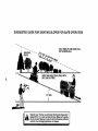
SLOPE OPERATION
Slopes are a major factor related to lossof-control and tipover accidents, which
can result in severe injury or death. All
slopes require extra caution. If you cannot
back up the slope or if you feel uneasy on
it, do not mow it.
DO:
• Mow up and down slopes, not across.
• Remove obstacles such as rocks, tree
limbs, etc.
• Watch for holes, ruts, or bumps.
Uneven terrain could overturn the
machine. Tall grass can hide obstacles.
• Use slow speed. Choose a low gear so
that you will not have to stop or shift
while on the slope.
• Follow the manufacturer's
recommendations for wheel weights or counterweights to improve stability.
• Use extra care with grass catchers or
other attachments.
These can change
the stability of the machine.
• Keep all movement on the slopes slow
and gradual. Do not make sudden
changes in speed or direction.
• Avoid starting or stopping on a slope. If
tires lose traction, disengage the
blades and proceed slowly straight
down the slope.
DO NOT:
• Do not turn on slopes unless necessary, and then, turn slowly and gradually downhill, if possible.
• Do not mow near drop-offs, ditches, or
embankments.
The mower could
suddenly turn over if a wheel is over
the edge of a cliff or ditch, or if an edge
caves in.
• Do not mow on wet grass. Reduced
traction could cause sliding.
• Do nottry to stabilize the machine by
putting your foot on the ground.
• Do not use grass catcher on steep
slopes,
3
CHILDREN
Tragic accidents can occur if the operator
is not alert to the presence of children.
Children are often attracted to the
machine and the mowing activity. Never
assume that children will remain where
you last saw them.
• Keep children out of the mowing area
and under the watchful care of another
responsible
adult.
• Be alert and turn machine off if children
enter the area.
• Before and when backing, look behind
and down for small children.
• Never carry children. They may fall off
and be seriously injured or interfere
with safe machine operation.
• Never allow children to operate the
machine.
• Use extra care when approaching
blind
corners, shrubs, trees, or other objects
that may obscure vision.
SERVICE
• Use extra care in handling gasoline
and other fuels. They are flammable
and vapors are explosive.
-Use only an approved container,
- Never remove gas cap or add fuel
with the engine running. Allow
engine to cool before refueling. Do
not smoke.
-Never refuel the machine indoors.
- Never store the machine or fuel
container inside where there is an
open flame, such as a water heater.
• Never run a machine inside a closed
area.
• Keep nuts and bolts, especially blade
attachment bolts, tight and keep
equipment in good condition.
• Never tamper with safety devices.
Check their proper operation regularly.
• Keep machine free of grass, leaves, or
other debris build-up. Clean oil or fuel
spillage. Allow machine to cool before
storing.
• Stop and inspect the equipment if you
strike an object. Repair, if necessary,
before restarting.
• Never make adjustments
or repairs
with the engine running.
• Grass catcher components are subject
to wear, damage, and deterioration,
which could expose moving parts or
allow objects to be thrown. Frequently
check components
and replace with
manufacturer's
recommended
parts,
when necessary.
• Mower blades are sharp and can cut.
Wrap the blade(s) or wear gloves, and
use extra caution when servicing them.
• Check brake operation frequently.
Adjust and service as required.
• Be alert and turn machine off if children
enter the area.
• Before and when backing, look behind
and down for small children.
• Mow up and down slopes (15 ° Max),
not across.
• Remove obstacles such as recks, tree
limbs, etc.
• Watch for holes, ruts, or bumps.
Uneven terrain could overturn the
machine. Taft grass can hide obstacles.
• Be sure the area is clear of other
people before mowing. Stop machine if
anyone enters the area.
• Never carry passengers
or children
even with the blades off.
• Do not mow in reverse unless absolutely necessary. Always look down
and behind before and while backing.
• Never carry children. They may fall off
and be seriously injured or interfere
with safe machine operation.
• Keep children out of the mowing area
and under the watchful care of another
responsible
adult.
4
• Use slow speed. Choose a low gear so
that you will not have to stop or shift
while on the slope.
• Avoid starting or stopping on a slope. If
tires lose traction, disengage the
blades and proceed slowly straight
down the slope.
• If machine stops while going uphill,
disengage
blades, shift into reverse
and back down slowly.
• Do not turn on slopes unless necessary, and then, turn slowly and gradually downhill, if possible.
ACAUTION:
Tow only the attachments
that are recommended
by and comply
with specifications
of the manufacturer
of
your tractor. Use common sense when
towing. Operate only at the lowest
possible speed when on a slope. Too
heavy of a load, while on a slope, is
dangerous. Tires can lose traction with
the ground and cause you to lose control
of your tractor.
_,WARNING:
Engine exhaust, some of its
constituents,
and certain vehicle components contain or emit chemicals known to
the State of California to cause cancer
and birth defects or other reproductive
harm.
_,WARNING:
Battery posts, terminals
and related accessories
contain lead and
lead compounds,
chemicals known to the
State of California to cause cancer and
birth defects or other reproductive
harm.
Wash hands after handling.
_Look for this symbol to point out
important safety precautions.
It means
CAUTION!H BECOMEAWARE!!!YOUR
SAFETY IS INVOLVED.
ACAUTION:
In order to prevent accidental starting when setting up, transporting,
adjusting or making repairs always
disconnect spark plug wire and place
wire where it cannot contact spark plug.
_I, CAUTION:
Do not coast down a hill in
neutral, you may lose control of the
tractor.
5
PRODUCT
Should you experience
any problem you
cannot easily remedy, please contact a
Sears or other qualified service center.
We have competent, well-trained
technicians and the proper tools to service or
repair this tractor.
Please read and retain this manual. The
instructions will enable you to assemble
and maintain your tractor properly. Always
observe the "SAFETY RULES".
REPAIR AGREEMENT
A Sears Repair Agreement is available
on this product. Contact your nearest
Sears store for details.
CUSTOMER
RESPONSIBILITIES
• Read and observe the safety rules.
• Follow a regular schedule in maintaining, caring for and using your tractor.
• Follow the instructions under "Maintenance" and "Storage" sections of this
owner's manual.
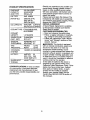
SPECIFICATIONS
GASOLINE
CAPACITY
AND TYPE:
3.5 GALLONS
UNLEADED
REGULAR
OILTYPE
SAE 10W30
(API-SF-SJ):
(ABOVE 32°F)
SAE 5W-30
(BELOW 32°F)
OILCAPACITY:
W/FILTER:
4.0PINTS
W/O FILTER: 3.5PINTS
COOLANT TYPE:
ETHYLENE GLYCOL
ANTIFREEZE
COOLANT
CAPACITY:
1.47 QUARTS
SPARK
CHAMPION
PLUG:
(GAP: .030")
RC14YC
GROUND
FORWARD:
5.8
SPEED(MPH):
REVERSE:
2.1
TIRE
PRESSURE:
FRONT:
REAR:
14 PSI
10 PSI
CHARGING
SYSTEM:
15AMPS
@ 3600RPM
BA'FI-ERY:
AMP/HR:
35
MIN. CCA: 280
CASE SIZE:U1R
BLADE BOLT
TORQUE:
45-55 FT. LBS
AWARNING:
This tractor is equipped
with an internal combustion
engine and
should not be used on or near any
unimproved
forest-covered,
brushcovered or grass-covered
land unless the
engine's exhaust system is equipped with
a spark arrester meeting applicable local
or state laws (if any). If a spark arrester is
used, it should be maintained
in effective
working order by the operator.
In the state of California the above is
required by law (Section 4442 of the
California Public Resources Code). Other
states may have similar laws. Federal
laws apply on federal lands. A spark
arrester for the muffler is available
through your nearest Sears Service
Center (See REPAIR PARTS section of
this manual).
CONGRATULATIONS on your purchase
of a new tractor. It has been designed,
engineered and manufactured to give
you the best possible dependability and
performance.
6
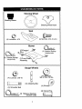
Steering Wheel
Steering Sleeve
Steering Wheel Insert
Seat
(4) Lockwasher
(4) Hex Bolts
5/16
5/16-18
x 3/4
Mower
(2)Flanged
(5) Retainer Springs
(double loop)
_t:_ ins
(2)
Retainer Springs
(single loop)
(1)Front
Assembly
%
Gauge Wheels
@
(4) Locknut
f
@
@
@
3/_4x)_SG
3/8-16
O
_o
(4) Adjusting Bar
(4) Shoulder
(4) Wheels_
Bolt
(4) Clevis Pins
_(4)
Retainer,S, prings
taouole Joop)
7
io
a.
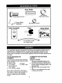
Nose Roller
(2) Washers
17/32 x 7/8 x 16 Ga.
Nose Roller
Brackets
(2) Locknuts
Video Cassette
5/16-18
Keys
Slope Sheet
(2) Keys
For Future Use
Your new tractor has been assembled at the factory with exception of those parts left
unassembled
for shipping purposes. To ensure safe and' proper operation of your
tractor all parts and hardware you assemble must be tightened securely. Use the
correct tools as necessary to insure proper tightness. Review the video cassette before
you begin.
TOOLS REQUIRED
ASSEMBLY
TO REMOVE TRACTOR
CARTON
FOR
UNPACK
A socket wrench set will make assembly
easier. Standard wrench sizes you need
are listed below.
(1) 9/16" wrench
(1) Pliers
(1) 1/2" wrench
(1) Utility knife
(1) 3/4" socket with
drive ratchet
(1) Tire
pressure
FROM
CARTON
1. Remove all accessible
loose parts
and parts boxes from shipping carton.
2. Cut, from top to bottom, along lines on
all four corners of shipping carton, and
lay panels flat.
3. Remove mower and packing materials.
4. Check for any additional loose parts
or boxes and remove.
gauge
When right or left hand is mentioned in
this manual, it means, from your point of
view, when you are in the operating
position (seated behind the steering
wheel).
8
BEFORE REMOVING
FROM SKID
ATTACH
STEERING
HOW TO SET UP YOUR TRACTOR
TRACTOR
CHECK
BATTERY
• Lift hood to raised position.
• If this battery is put into service after
month and year indicated on label
(label located between terminals)
charge battery for minimum of one hour
at 6-10 amps. (See "BATTERY"
in
Maintenance
section of this manual for
WHEEL
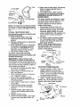
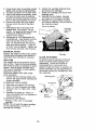
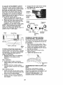
1. Remove hex bolt, lock washer and
large flat washer from steering shaft.
2. Position front wheels of the tractor so
they are pointing straight forward.
Slide the steering sleeve over the
steering shaft.
4. Position steering wheel so cross bars
are horizontal (left to right) and slide
onto steering wheel adapter.
5. Secure steering wheel to steering
shaft with hex bolt, lock washer and
large flat washer previously removed.
Tighten securely.
6. Snap steering wheel insert into center
of steering wheel.
7. Remove protective materials from
tractor hood and grill.
IMPORTANT:
Check for and remove any
staples in skid that may puncture tires
where tractor is to roll off skid.
3.
charging
instructions).
"'_-_..-
INSTALL
,--
, , Label
SEAT
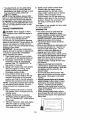
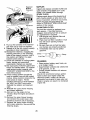
Seat position should be adjusted forward
or backward so that the operator can
comfortably reach clutch/brake pedal and
safely operate the tractor.
1. Release L.H. seat slide on seat pan
by pulling out on adjustment handle
and sliding it to the rear position
exposing seat mounting holes from
bottom. Slide R.H. slide to same rear
position.
2. Mount rear of seat on slides using
mounting bolts and lock washers as
shown.
3. Pull out on adjustment handle and
slide seat all the way forward. Install
front mounting bolts and lock washers.
Tighten all mounting bolts securely.
4. Lower seat into operating position and
sit on seat. Press clutch/brake pedal
all the way down. If operating position
is not comfortable, adjust seat.
To adjust seat: Grasp adjustment handle
and pull out, slide seat to desired position
and release adjustment handle.
Steering
Shaft
Steering
Sleeve
9
L.h. Seat Slide
_=_,_
Seat
Seat Pan,_
Adjustment
Handle_
Lock'_
_
\
_
_3
"_,._,_.=_'_k_'_\
_R.H.
Seat Slide
Washe__
Mounti Bo,t
ii
NOTE: You may now roll or drive yourtractor
off the skid. Follow the appropriate instruction below to remove the tractor from the
skid.
TO ROLL TRACTOR
OFF SKID
(See Operation section for location and
function of controls)
1. Press lift lever plunger and raise
attachment lift lever to its highest
position.
2. Release parking brake by depressing
clutch/brake
pedal.
3. Place freewheel control in freewheeling position to disengage transmission (See "TO TRANSPORT"
in the
Operation section of this manual).
4. Roll tractor forward off skid.
TO DRIVE
TRACTOR
(See Operation
section
function of controls)
10.Apply brake to stop tractor, set parking
brake and place gearshift lever in
neutral position.
11 .Turn ignition key to "OFF" position.
Continue with the instructions that follow.
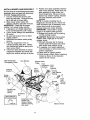
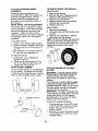
ASSEMBLE
GAUGE WHEELS
TO
MOWER
DECK
The gauge wheels are designed to keep
the mower deck in proper position when
operating mower. Be sure they are
properly adjusted to ensure optimum
mower performance.
1. Slide gauge wheel bar down into
bracket channel, Be sure that gauge
wheel bar aligning holes are on top.
Assemble gauge wheels as shown
using shoulder bolts, 3/8 washers and
3/8-16 center Iocknuts and tighten
securely.
2. For ease of mower to tractor assembly, raise gauge wheels to highest
position and retain with clevis pins
and spring retainers.
NOTE: Adjust gauge wheels before
operating mower. See 9"0 ADJUST
GAUGE WHEELS" in the Operation
section of this manual.
Retainei
Pin
OFF SKID
for location
Shoulder
and
_WARNING:
Before starting, read,
understand and follow all instructions in
the Operation section of this manual. Be
sure tractor is in a well-ventilated area. Be
sure the area in front of tractor is clear of
other people and objects.
1. Be sure all the above assembly steps
have been completed.
2. Check engine oil level and fill fuel
tank with gasoline.
3. Place freewheel control in "transmission engaged" position.
4. Sit on seat in operating position,
depress clutch/brake pedal and set
the parking brake.
5. Place motion control lever in neutral
(N) position.
6. Press lift lever plunger and raise
attachment lift lever to its highest
position.
7. Start the engine. After engine has
started, move throttle control to idle
position.
8. Release parking brake.
9. Slowly move the motion control lever
forward and slowly drive tractor off
skid.
Gau(
Wheel
3/8-16 Center
3/8
Washer
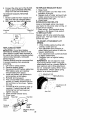
TO A'I-FACH NOSE ROLLER
1. Position brackets, 17/32 x 7/8 x 16
gauge washers, and nose roller
between deck mounting brackets as
shown.
Be sure to position brackets
on correct side, as shown.
2. Install hex bolts and lock nuts as
shown. Tighten hardware securely.
NOTE: Be sure bracket tabs are positioned in tab holes in deck brackets.
Tab
Nose Roller
Lock
Nut
Hex Bolt
"A"
Bracket
10
"B" Bracket
INSTALL
MOWER
AND
DRIVE
9.
Position front plate assembly between
front mower brackets. Raise deck and
plate assembly to align holes and
insert flanged pins. Secure pins with
double loop retainer springs between
the plate assembly and mower
brackets.
NOTE: To assist in locating hole in
flanged pin, the hole in pin is inline with
notch on head of pin. If necessary, move
mower side-to-side
to give space
between plate and mower brackets.
IMPORTANT:
Check belt for proper
routing in all mower pulley grooves.
10.Engage belt tension rod by pushing
rod into locking bracket.
CAUTION:
Belt tension rod is spring
loaded. Have a tight grip on rod and
engage slowly.
11.Connect
anti-sway bar to chassis
bracket under left footrest and retain
with double loop retainer spdng.
12.1f equipped, turn height adjustment
knob clockwise to remove slack from
mower suspension.
13.Raise deck to highest position.
14.Adjust gauge wheels before operating
mower as shown in the Operation
section of this manual.
BELT
Be sure tractor is on level surface and mower
suspension arms are raised with attachment
lift control. Engage parking brake.
1. Cut and remove ties securing antisway bar and belts. Swing anti-sway
bar to left side of mower deck.
2. Slide mower under tractor with
deflector shield to right side of tractor.
IMPORTANT:
Check belt for proper
routing in all mower pulley grooves.
3. If equipped, turn height adjustment
knob counterclockwise
until it stops.
4. Lower mower linkage with attachment
lift control.
5. Be sure belt tension rod is in disengaged position.
6. Install belt into electric clutch pulley
groove.
7. Place the suspension arms on
outward pointing deck pins. Retain
with double loop retainer spring with
loops up as shown.
8. Install front plate assembly to tractor
suspension
brackets and retain with
single loop retainer springs as shown.
Belt Tension Rod
Disengaged Position
Lock Bracket
Electric Clutch
Pulley\
\
Front
Suspension
Front
Front \Brackets
Mower \
Bracket\
Chassis _
Brack
Assembly
Plate
,,Loop Retainer
Springs
Gauge
Wheel
"_S
/_
Double Loop
Retainer
Spring
le
Loop
Retainer
Flanged
j__)
Anti-Sway
Bar
.J
/-
•
Suspension Arms
Double Loop
Retainer Spring
(Outward pointing
deck pins)
" _
11
Springs
J
Deflector Shield
CHECK
TIRE
_CHECKUST
PRESSURE
The tires on your tractor were overinflated
at the factory for shipping purposes.
Correct tire pressure is important for best
cutting performance.
• Reduce tire pressure to PSI shown in
"PRODUCT SPECIFICATIONS"
section
of this manual.
CHECK MOWER LEVELNESS
BEFORE YOU OPERATEAND
ENJOY
YOU R N EW TRACTOR, WE WISH TO
ASSURE THAT YOU RECEIVE THE BEST
PERFORMANCE
AND SATISFACTION
FROM THIS QUALITY PRODUCT.
For best cutting results, mower should be
properly leveled. See "TO LEVEL
MOWER HOUSING"
in the Service and
Adjustments
section of this manual.
CHECK FOR PROPER POSITION OF
ALL BELTS
,/
See the figures that are shown for
replacing motion, mower drive, and
mower blade drive belts in the Service
and Adjustments section of this manual.
Verify that the belts are routed correctly.
PLEASE REVIEWTHE
CHECKLIST:
FOLLOWING
All assembly instructions have been
completed.
,/No remaining loose parts in carton.
/ Battery is properly prepared and
charged.
(Minimum 1 hour at 6 amps).
,/Seat
is adjusted comfortably and
tightened
securely.
,/Ail tires are properly inflated. (For
shipping purposes, the tires were
overinflated at the factory).
,/Be sure mower deck is properly leveled
side-to-side/front-to-rear
for best cutting
results. (Tires must be properly inflated
for leveling).
,/Check
mower and drive belts. Be sure
they are routed properly around pulleys
and inside all belt keepers.
,/Check
wiring. See that all connections
are still secure and wires are properly
clamped.
•/ Before driving tractor, be sure freewheel control is in drive position.
WHILE LEARNING HOW TO USE YOUR
TRACTOR,
PAY EXTRAAI-FENTION
TO
THE FOLLOWING IMPORTANT ITEMS:
#" Engine oil is at proper level.
/ Engine coolant is at proper level.
,/Fuel tank is filled with fresh, clean,
regular unleaded gasoline.
,/Become
familiar with all controls - their
location and function.
Operate them
before you start the engine.
,/Be sure brake system is in safe
operating
condition.
,/It is important to purge the transmission
before operating your tractor for the first
time. Follow proper starting and
transmission
purging instructions
(See
'%0 START ENGINE" and "PURGE
TRANSMISSION"
in the Operation
section of this manual).
12
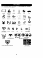
These symbols may appear on your tractor or in literature
Learn and understand their meaning.
supplied with the product.
I'- ;I
BATTERY
CAUTION OR
WARNING
REVERSE
ENGINE ON
ENGINE OFF
OIL PRESSURE
LIGHTS ON
FUEL
CHOKE
MOWER HEIGHT
PARKING BRAKE
LOCKED
R N
ATTACHMENT
CLUTCH ENGAGED
REVERSE
NEUTRAL
ATTACHMENT
IGNITION
FORWARD
FAST
L
HIGH
LOW
KEEP AREA CLEAR
!
OVER TEMP
LIGHT
H
CLUTCH DISENGAGED
SLOW
UNLOCKED
MOWER LIFT
®3I
PARKING BRAKE
SLOPE HAZARDS
(SEE SAFETY RULES SECTION)
FREE WHEEL
(Automatic Models only)
DANGER, KEEP HANDS AND FEET AWAY
13
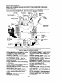
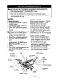
KNOW YOUR TRACTOR
READ THIS OWNER'S
YOUR TRACTOR
MANUAL
AND SAFETY
RULES
BEFORE
OPERATING
Compare the illustrations with your tractor to familiarize yourself with the locations of
various controls and adjustments.
Save this manual for future reference.
Ignition
ht Switch
Ammeter
Hourrneter
Switch
Attachment
Switch
Clutch
Overtemp light _
Lever
Plunger
Throttle Control
Choke
Control
Brake
Pedal
Attachment
Lift Lever
Parking Brake Lever
Height
Adjustment
Knob
Motion Drive
Belt Tension
Handle
Motion Control
Lever
Free Wheel
Our tractors conform to the safety standards of the
American National Standards Institute.
ATTACHMENT
CLUTCH SWITCH - Used
to engage the mower blades, or other
attachments
mounted to your tractor.
THROTTLE CONTROL
- Used to control
engine speed.
CLUTCH/BRAKE
PEDAL - Used for
declutching and braking the tractor and
starting the engine.
CHOKE CONTROL
- Used when starting
a cold engine.
HEIGHT ADJUSTMENT
KNOB - Used to
adjust the mower cutting height.
IGNITION SWITCH - Used for starting and
stopping the engine.
ATTACHMENT
LIFT LEVER - Used to
raise, lower, and adjust the mower deck
or other attachments mounted to your
tractor.
AMMETER
discharging
LIFT LEVER
PLUNGER
- Used to release
attachment lift lever when changing its
position.
PARKING BRAKE LEVER - Locks clutch/
brake pedal into the brake position.
MOTION CONTROL LEVER - Selects the
speed and direction of tractor.
FREEWHEEL
CONTROL
- Disengages
transmission for pushing or slowly towing
the tractor with the engine off.
HOURMETERIndicates hours of
operation.
OVERTEMP LIGHT: Indicates overheated
coolant during engine operation.
LIGHT SWITCH - Turns the headlights on
and off.
MOTION DRIVE BELT TENSION HANDLEUsed when changing motion drive belt and, if
necessary, starting engine under extremely
cold conditions.
- Indicates charging (+) or
(-) of battery.
14
The operation of any tractor can result in foreign objects thrown into the
eyes, which can result in severe eye damage.
Always wear safety glasses
or eye shields while operating your tractor or performing any adjustments
or repairs. We recommend a wide vision safety mask over spectacles or
standard safety glasses.
HOW TO USE YOUR TRACTOR
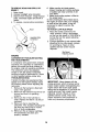
TO SET PARKING
BRAKE
Your tractor is equipped with an operator
presence sensing switch. When engine
is running, any attempt by the operator to
leave the seat without first setting the
parking brake will shut off the engine.
1. Depress brake pedal into full "BRAKE"
position and hold.
2. Place parking brake lever in =ENGAGED" position and release
pressure from brake pedal. Pedal
should remain in "BRAKE" position.
Make sure parking brake will hold
tractor secure.
Push-In to
Attachment Clutch
Choke _'Disengage"
Switch Pull Out to
. ,age-
Throttle _(_,\'_/"_'_'_
Control.,.\/j_ __L_
/
_¢_'_
• Never use choke to stop engine.
IMPORTANT:
Leaving the ignition switch
in any position other than "OFF" will
cause the battery to be discharged,
(dead).
NOTE: Under certain conditions when
tractor is standing idle with the engine
running, hot engine exhaust gases may
cause "browning" of grass. To eliminate
this possibility, always stop engine when
stopping tractor on grass areas.
_I, CAUTION:
Always stop tractor
completely, as described above, before
leaving the operator's position; to empty
grass catcher, etc.
TO USE THROTTLE
CONTROL
Always operate engine at full throttle.
• Operating engine at less than full
throttle reduces the battery charging
rate.
• Full throttle offers the best bagging
mower performance.
TO USE CHOKE CONTROL
Use choke control whenever you are
starting a cold engine. Do not use to start
a warm engine.
• To engage choke control, pull knob out.
Slowly push knob in to disengage.
_.Hei h
%./
g t" f_\
Parking Brake
_/_
Adjustment _Engaged"
Position
/ "_Knoe
\--Clutch/Brake Pedal
"Disengaged" Position
"Drive" Position
STOPPING
MOWER
BLADES
_MOVE
FORWARD AND BACKWARD
CAUTION: Do not attempt to operate
motion control lever when the parking brake is
set or when the brake pedal is depressed.
Doing so may result in misadjustment to the
drive control system.
The direction and speed of movement is
controlled by the motion control lever.
1. Start tractor with motion control lever in
neutral (N) position.
2. Release parking brake.
3. Slowly move motion control lever to
desired position.
-
• To stop mower blades,move attachment clutch switch to "DISENGAGED"
position.
GROUND
DRIVE
-
• To stop ground drive, depress brake
pedal into full "BRAKE" position.
IMPORTANT: The motion control lever
returns to neutral (N) position when the
brake pedal is fully depressed.
ENGINE
and
TO ADJUST
• Move throttle control to slow position.
NOTE: Failure to move throttle control to
slow position and allowing engine to
idle before stopping may cause engine
to "backfire".
• Turn ignition key to "OFF" position
remove key. Always remove key
when leaving tractor to prevent
unauthorized
use.
MOWER
CUTTING
HEIGHT
The cutting height is controlled by turning
the height adjustment knob in desired
direction.
• Turn knob clockwise (_)
to raise
cutting height.
• Turn knob counterclockwise (P-_)to
lower cutting height.
and
15
TO OPERATE
The cutting height range is approximately 1-1/2" to 4-1/2". The heights are
measured from the ground to the blade
tip with the engine not running.
These
heights are approximate
and may vary
depending
upon soil conditions,
height
of grass and types of grass being
mowed.
• The average lawn should be cut to
approximately
2-1/2 inches during
the cool season and to over 3 inches
during hot months.
For healthier and
better looking lawns, mow often and
after moderate growth.
• For best cutting performance,
grass
over 6 inches in height should be
mowed twice. Make the first cut
MOWER
Your tractor is equipped with an operator
presence sensing switch. Any attempt by
the operator to leave the seat with the
engine running and the attachment
clutch
engaged will shut off the engine.
1. Select desired height of cut.
2. Lower mower with attachment lift
control.
3.
Start mower blades by engaging
attachment clutch control.
TO STOP
attachment
MOWER BLADES
clutch control.
- disengage
_I_CAUTION:
Do not operate the mower
without either the entire grass catcher, on
mowers so equipped, or the deflector
shield in place.
relatively high; the second to desired
height.
TO ADJUST GAUGE WHEELS
Attachment Clutch
Switch Pull Out to
"Engage"
Gauge wheels are properly adjusted
when they are slightly off the ground
when mower is at the desired cutting
height in operating position. Gauge
wheels then keep the deck in proper
position to help prevent scalping in most
terrain conditions.
NOTE: Be sure tractor is on a flat level
surface.
1. Lower mower and adjust mower to
desired cutting height.
2. Remove retainer spring and clevis pin
which secure each gauge wheel bar.
3. Lower gauge wheels to ground. Raise
gauge wheels slightly to align holes in
bracket and gauge wheel bar and
insert clevis pin. Gauge wheels
should be slightly off the ground.
4. Replace retainer spring into clevis pin.
5. Be sure all gauge wheels are in the
same setting.
IMPORTANT:
Be sure to readjust gauge
wheels if you change the cutting height
of the mower deck.
Attachemnt Lift
Lever High
Position
/,,
,,S';'_Low
Position
to
"Disengage"
TO OPERATE
ON HILLS
Deflector
Shield
411CAUTION:
Do not drive up or down
hills with slopes greater than 15 ° and do
not drive across any slope.
• Choose the slowest speed before
starting up or down hills.
• Avoid stopping or changing speed on
hills.
• If stopping is absolutely necessary,
push brake pedal quickly to brake
position and engage parking brake,
IMPORTANT:
The motion control lever
returns to neutral (N) position when the
brake pedal is depressed.
• To restart movement, slowly release
parking brake and brake pedal.
• Slowly move motion control lever to
slowest setting.
• Make all turns slowly.
Retainer
Spring_
TO TRANSPORT
When pushing or towing your tractor, be
sure to disengage transmission
by
placing freewheel
control in freewheeling
position.
Free wheel control is located at
the rear drawbar of tractor.
Clevis
Pin
16
1. Raiseattachmentlift to highestposition
with attachment lift control.
2. Pull freewheel control out and into the
slot and release so it is held in the
disengaged
position.
• Do not push or tow tractor at more than
two (2) MPR.
• To re-engage transmission,
reverse
above procedure.
NOTE: To protect hood from damage when
transporting your tractor on a truck or a
trailer, be sure hood is closed and secured
to tractor. Use an appropriate means of
tying hood to tractor (rope, cord, etc.).
CHECK
1.
Unhook the four retaining straps and
remove the upper blower housing and
screen assembly.
2. Observe coolant reservoir. Coolant
should be between the "MAX" and
"MIN" level marks.
ACAUTION:
Do not poor coolant into a
hot engine or you may damage the
cylinder head or block. Do not operate the
engine without coolant.
3. If necessary, add coolant by removing
reservoir cap. Use only ethylene
glycol antifreeze and soft water in the
mixture ratio specified on the antifreeze container.
Tow only the attachments that are
recommended by and comply with
specifications of the manufacturer of your
tractor. Use common sense when towing.
Too heavy of a load, while on a slope, is
dangerous. Tires can lose traction with
the ground and cause you to lose control
of your tractor.
STARTING
ENGINE
THE
Replace
Reinstall
reservoir cap.
the upper blower
housing
uapnpde
s cre e n assembly.
Blower
Housing
Assembly
TOWING CARTS AND OTHER A'I-FACHMENTS
CHECK
LEVEL
_,CAUTION:
Check coolant level at
reservoir only. Do not open radiator cap.
• Check coolant with tractor on level
surface.
4.
5.
BEFORE
COOLANT
Retaining
Straps
Coolant
Reservoir
Cap
ENGINE
OIL LEVEL
The engine in your tractor has been
shipped, from the factory, already filled
with summer weight oil
1. Check engine oil with tractor on level
ground.
2. Unthread and remove oil fill cap/
dipstick; wipe oil off. Reinsert the
dipstick into the tube and rest oil fill
cap on the tube. Do not thread the
cap onto the tube. Remove and read
oil level. If necessary, add oil until
"FULL" mark on dipstick is reached.
Do not overfill.
ADD GASOLINE
• Fitl fuel tank. Use fresh, clean, regular
unleaded gasoline with a minimum of 87
octane. (Use of leaded gasoline will
increase carbon and lead oxide deposits
and reduce valve life). Do not mix oil with
gasoline. Purchase fuel in quantities that
can be used within 30 days to assure fuel
freshness.
• For cold weather operation you should
change oil for easier starting (See "OIL
VISCOSITY
CHART" in the Maintenance section of this manual).
• To change engine oil, see the Maintenance section in this manual.
IMPORTANT: When operaUng in temperatures below 32°F(0°C), use fresh, clean
winter grade gasoline to help insure good
cold weather starting.
17
AWARNING:
Experience indicates !hat
alcohol blended fuels (called gasohol or
using ethanol or methanol) can attract
moisture which leads to separation and
formation of acids during storage. Acidic gas
can damage the fuel system of an engine
while in storage. To avoid engine problems,
the fuel system should be emptied before
storage of 30 days or longer. Drain the gas
tank, start the engine and let it run until the
fuel lines and carburetor are empty. Use
fresh fuel next season. See Storage
Instructions for additional information. Never
use engine or carburetor cleaner products in
the fuel tank or permanent damage may
occur.
_CAUTION:
Fill to bottom of gas tank filler
neck. Do not overfill. Wipe off any spilled oil
or fuel. Do not store, spill or use gasoline
near an open flame.
OVERTEMP LIGHT
Located on the dash of your tractor, this light
alerts you to the engine being overheated
which requires immediate attention.
• Light should come on when engine is not
running and the key switch is in "ON"
position, this is a test to be sure the light is
working.
• If light comes on while operating the
engine, stop the engine. Find and correct
the problem. See "Engine Overheats" in
the Trouble Shooting
section of this manual.
TO START
ENGINE
When starting the engine for the first time or if
the engine has run out of fuel, it will take extra
cranking time to move fuel from the tank to
the engine.
1. Be sure freewheel control is in the
transmission
engaged position.
2. Sit on seat in operating position,
depress brake pedal and set parking
brake.
3. Move attachment clutch to "DISENGAGED" position.
4. Move throttle control to fast position
5. Pull choke control out for a cold
engine start attempt. For a warm
engine start attempt the choke control
may not be needed.
NOTE: Before starting, read the warm and
cold starting procedures below.
6. Insert key into ignition and turn key
clockwise to "START" position and
release key as soon as engine starts.
Do not run starter continuously
for
more than fifteen seconds per minute.
If the engine does not start after
several attempts, push choke control
in, wait a few minutes and try again. If
engine still does not start, pull the
choke control out and retry.
WARM WEATHER STARTING (50 ° F and
above)
7. When engine starts, slowly push
choke control in until the engine
begins to run smoothly. If the engine
starts to run roughly, pull the choke
control out slightly for a few seconds
and then continue to push the control
in slowly.
• The attachments and ground drive can
now be used. If the engine does not accept
the load, restart the engine and allow it to
warm up for one minute using the choke
as described above.
COLD WEATHER
STARTING (50 ° F and
below)
7. When engine starts, slowly push
choke control in until the engine
begins to run smoothly. Continue to
push the choke control in small steps
allowing the engine to accept small
changes in speed and load, until the
choke control is fully in. If the engine
starts to run roughly, pull the choke
control out slightly for a few seconds
and then continua to push the control
in slowly. This may require an engine
warm-up period from several seconds
to several minutes, depending on the
temperature.
NOTE: In extreme cold conditions, if
engine will not start you may need to
disengage the motion drive belt as
follows:
1. Be sure parking brake is engaged.
2. Remove retainer spring from the drive
belt tension handle to relieve belt
tension.
3. Start engine and allow it to warm up
for three (3) minutes.
4. Shut-off engine and engage parking
brake.
5. Engage drive belt tension handle and
replace the retainer spring.
AUTOMATIC TRANSMISSION
WARM UP
Before driving the unit in cold weather,
the transmission
should be warmed up as
follows:
1. Be sure the tractor is on level ground.
2. Place the motion control lever in
neutral. Release the parking brake
and let the brake slowly return to
operating
position.
3. Allow one minute for transmission
to
warm up. This can be done during the
18
engine
warm
up period.
• The attachments can be used during
the engine warm-up period after the
transmission has been warmed up and
may require the choke control be
pulled out slightly.
NOTE: If at a high altitude (above 3000
feet) or in cold temperatures (below 32 F)
the carburetor fuel mixture may need to
be adjusted for best engine performance,
See "TO ADJUST CARBURETOR" in the
Service and Adjustments section of this
manual.
PURGE TRANSMISSION
_CAUTION:
Never engage or disengage freewheel lever while the engine is
running.
To ensure proper operation and performance, it is recommended that the
transmission be purged before operating
tractor for the first time. This procedure will
remove any trapped air inside the transmission which may have developed during
shipping of your tractor.
IMPORTANT:
Should your transmission
require removal for service or replacement,
it should be purged after reinstallation
before operating the tractor.
1. Place tractor safely on level surface
with engine off and parking brake set.
2. Disengage transmission
by placing
freewheel control in freewheeling
position (See "TO TRANSPORT"
in
this section of manual).
3. Sitting in the tractor seat, start engine.
After the engine is running, move
throttle control to slow position.
Disengage
parking brake.
4. Move motion control lever to full
forward position and hold for five (5)
seconds. Move lever to full reverse
position and hold for five (5) seconds.
Repeat this procedure three (3) times.
NOTE: During this procedure there will be
no movement of drive wheels. The air is
being removed from hydraulic drive
system.
5. Move motion control lever to neutral
(N) position. Shut- off engine and set
parking brake.
6. Engage transmission
by placing
freewheel control in driving position
(See "TO TRANSPORT"
in this section
of manual).
7. Sitting in the tractor seat, start engine.
After the engine is running, move
throttle control to half (1/2) speed.
Disengage
parking brake.
8.
Slowly move motion control lever
forward, after the tractor moves
approximately
five (5) feet, slowly
move motion control lever to reverse
position. After the tractor moves
approximately
five (5) feet return the
motion control lever to the neutral (N)
position. Repeat this procedure with
the motion control lever three (3)
times.
Your tractor is now purged and now ready
for normal operation.
MOWlNGTIPS
• Tire chains cannot be used when the
mower housing is attached to tractor.
• Mower should be pmpedy leveled for best
mowing performance. See "TO LEVEL
MOWER HOUSING" in the Service and
Adjustments section of this manual.
• The left hand side of mower should be
used for trimming.
• Drive so that clippings are discharged onto
the area that has been cut. Have the cut
area to the right of the tractor. This will
result in a more even distribution of
clippings and more uniform cutting.
• When mowing large areas, start by turning
to the right so that clippings will discharge
away from shrubs, fences, driveways, etc.
After one or two rounds, mow in the
opposite direction making left hand tums
until finished.
• If grass is extremely tall, it should be
mowed twice to reduce load and possible
fire hazard from dried clippings. Make first
cut relatively high; the second to the
desired height.
• Do not mow grass when it is wet. Wet
grass will plug mower and leave undesirable dumps. Allow grass to dry before
mowing.
• Always operate engine at full throttle
when mowing to assure better mowing
performance and proper discharge of
material. Regulate ground speed by
selecting a low enough gear to give the
mower cutting performance as well as the
quality of cut desired.
• When operating attachments, select a
ground speed that will suit the terrain and
give best performance of the attachment
being used.
f
1
f
C----19
J
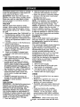
BEOU
OERV,CE
'R
AS YOU COMPLETE
Check
Operation
Check Brake
Tire Pressure
T
Check Operator Presence
Intedock Systems
R
Check for Loose Fasteners
_
_ _b
_V _
and
I_
_
1_7
T
Lubrication
A
0
Check Battery Level
Sharpen/Replace
Mower Blades
Clean Battery and Terminals
_S4
Check Transaxle
ll_
R
Chail
I1_
Check Engine
E
N
Clean
Clean
if
Cooling
Adjust Blade Belt(s)
Adjust Motion
Change
Tension
Drive Belt(s)
I_s
Tension
Oil Level
V*s
if
ll_
Engine Oil
Air Screen
Filter
Air
I_,=t:
_:
v"
Inspect Muffler/Spark
Arrester
Replace Oil Filter (If equipped)
N
Change
I
2
3
4
5
V'
_2
Fuel Filter
If
Coolant
I_e
- Change more often when operat;ng under a rmaW load or in high ambient
- Servk_e more often when operating in dkly or dusty ¢ord_Uons.
- If equipped with oll filter, change ol lively 50 hOUlS,
- Replace blades mo_ often when rncwing in sandy soil.
° If equipped with ad_Jslable system,
GENERAL
t_mtum=.
6 - N<_ mq.Jtred If aqulpped with n'_-Ir
ee batlerj.
7 - "_ght Im front axle pivot bolt to 35 _-Ibs. maximum.
DO not ovor tight _1.
8 ° Have your nearest authorized P,el'_ k_l centDr/departme_
pedoml thai service.
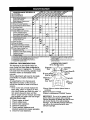
RECOMMENDATIONS
The warranty on this tractor does not
cover items that have been subjected to
operator abuse or negligence, To receive
full value from the warranty, operator must
maintain tractor as instructed in this
manual.
Some adjustments
will need to be made
periodically
to properly maintain your
tractor.
All adjustments
in the Service and
Adjustments
section of this manual
should be checked at least once each
season.
• Once a year you should replace the
spark plug, clean or replace air filter,
and check blades and belts for wear. A
new spark plug and clean air filter
assure proper air-fuel mixture and help
your engine run better and last longer.
BEFORE EACH USE
1. Check engine oil level.
2. Check coolant level.
3.
4.
5.
_.2
Replace Spark Plug
Clean Engine Cooling Fins
Replace Air Filter Paper Cartridge
Replace
V'
Check brake operation.
Check tire pressure.
Check operator presence and
interlock systems for proper operation.
6. Check for loose fasteners.
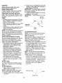
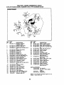
LUBRICATION CHART
(i) Tie Rod Ball Joints
_) Spindle ---1_'_
V--- Spindle _)
Zerk
_-'J__ :=_.:
=__=_ Zerk
_'J]
"_'_"
-" - 7LL_,,..FrontWheel (_)
_) Front W_hee/'-'_ "_,,'_-,"_
Bearing
Bearing _-:_----"/'_
_)Steering F _ 1 _
Sector
_
,,.
Gear Teetl_/
_
rK
_'Engine_)
-
_
{_/_
!"1
(_)M_andrel
er.
(DSpray Silicone Lubdant (Move Boots to
Lubricate)
_General Purpose Grease
(_)Refer to Maintenance "ENGINE" Section
IMPORTANT: Do not oil or grease the pivot
points which have special nylon bearings.
Viscous lubricants will attract dust and dirt that
will shorten the life of the self-lubricating
bearings. If you feel they must be lubricated,
use only a dry, powdered graphite type
lubricant sparingly.
2O
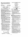
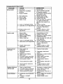
TRACTOR
3.
Install new or resharpened
blade with
stamped "THIS SIDE UP" facing deck
and mandrel assembly.
IMPORTANT:
To ensure proper assembly,
center hole in blade must align with star
on mandrel assembly.
4. Install and tighten blade bolt securely
(45-55 Ft. Lbs. torque).
IMPORTANT:
Special blade bolt is heat
treated.
Mandrel
Assembly
Always observe safety rules when
performing any maintenance.
BRAKE OPERATION
If tractor requires more than six (6) feet
stopping distance at high speed in
highest gear, then brake must be adjusted. (See "TO ADJUST BRAKE" in the
Service and Adjustments
section of this
manual).
TIRES
• Maintain proper air pressure in all tires
(See "PRODUCT SPECIFICATIONS"
section of this manual).
• Keep tires free of gasoline, oil, or insect
control chemicals which can harm
rubber.
• Avoid stumps, stones, deep ruts, sharp
objects and other hazards that may
cause tire damage.
NOTE: To seat tire punctures and prevent
flat tires due to slow leaks, tire sealant
may be purchased from your local parts
dealer. Tire sealant also prevents tire dry
rot and corrosion.
OPERATOR
PRESENCE SYSTEM
B_ade
Blade Bolt
4 _,
(Special)_"
CJnter
"" .. _'_ Star
Hole
TO SHARPEN
BLADE
NOTE: We do not recommend sharpening blade - but if you do, be sure the
blade is balanced.
Care should be taken to keep the blade
balanced.
An unbalanced
blade will
cause excessive vibration and eventual
damage to mower and engine.
• The blade can be sharpened with a file
or on a grinding wheel. Do not attempt
to sharpen while on the mower.
• To check blade balance, you will need
a 5/8" diameter steel bolt, pin, or a cone
balancer.
(When using a cone balancer, follow the instructions
supplied
with balancer.)
NOTE:
Do not use a nail for balancing
blade. The lobes of the center hole may
appear to be centered, but are not.
• Slide blade on to an unthreaded
portion of the steel bolt or pin and hold
the bolt or pin parallel with the ground.
If blade is balanced, it should remain in
a horizontal position.
If either end of
the blade moves downward, sharpen
the heavy end until the blade is
balanced.
For best results mower blades must be
kept sharp. Replace bent or damaged
blades.
BLADE REMOVAL
position
_-_
L
Be sure operator presence and interlock
systems are working properly.
If your
tractor does not function as described,
repair the problem immediately.
• The engine should not start unless the
brake pedal is fully depressed
and
attachement clutch control is in the
disengaged
position.
• When the engine is running, any
attempt by the operator to leave the
seat without first setting the parking
brake should shut off the engine.
• When the engine is running and the
attachment clutch is engaged, any
attempt by the operator to leave the
seat should shut off the engine.
• The attachment clutch should never
operate unless the operator is in the
seat.
BLADE CARE
1. Raise mower to highest
allow access to blades.
-
S_
to
NOTE: Protect your hands with gloves
and/or wrap blade with heavy cloth.
2. Remove blade bolt by turning counterclockwise.
5/8" Bolt or Pin
--
_:_
/.
.
/
Center
21
_ -
Hole
?_-Blade
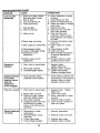
BATTERY
TRANSAXLE
Your tractor has a battery charging system
which is sufficient for normal use. However, periodic charging of the battery with
an automotive
charger will extend its life.
• Keep battery and terminals clean.
• Keep battery bolts tight.
• Keep small vent holes open.
• Recharge at 6-10 amperes for 1 hour.
NOTE: The original equipment battery on
your tractor is maintenance
free. Do not
attempt to open or remove caps or covers.
Adding or checking level of electrolyte is
not necessary.
The transaxle was sealed at the factory
and fluid maintenance is not required for
the life of the transaxle. Should the
transaxle ever leak or require servicing,
contact a Sears or other qualified service
center.
TO CLEAN
BATTERY
AND TERMINALS
PUMP FLUID
ENGINE
LUBRICATION
Only use high quality detergent oil rated
with API service classification SF-SJ.
Select the oil's SAE viscosity grade
according to your expected operating
temperature.
SAE VISCOSITY
Corrosion and dirt on the battery and
terminals can cause the battery to "leak"
power.
1. Remove terminal guard.
2. Disconnect BLACK battery cable first
then RED battery cable and remove
battery from tractor.
3. Rinse the battery with plain water and
dry.
4. Clean terminals and battery cable
ends with wire brush until bright.
5, Coat terminals with grease or petroleum jelly.
6. Reinstall battery (See "REPLACING
BATTERY" in the SERVICE AND
ADJUSTMENTS
section of this
manual).
V-BELTS
Check V-belts
for deterioration
and wear
after 100 hours of operation and replace
if necessary. The belts are not adjustable.
Replace belts if they begin to slip from
wear.
TRANSAXLE
COOLING
The transmission
fan and cooling fins
should be kept clean to assure proper
cooling.
Do not attempt to clean fan or transmission while engine is running or while the
transmission
is hot. To prevent possible
damage to seals, do not use high
pressure water or steam to clean
transaxle.
• Inspect cooling fan to be sure fan
blades are intact and clean.
• Inspect cooling fins for dirt, grass
clippings and other materials.
To
prevent damage to seals, do not use
compressed
air or high pressure
sprayer to clean cooling fins.
F
C
-2o
-30
, 0
.20
, 30
.10
GRADES
_-_,
0
so __loo-_0
20
3°C3°
HANGE _
]I
Change the oil after every 50 hours of
operation or at least once a year if the
tractor is not used for 50 hours in one
year.
Check the crankcase oil level before
starting the engine and after each eight
(8) hours of operation.
Tighten oil fill cap/
dipstick securely each time you check the
oil level.
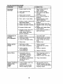
TO CHANGE
ENGINE
OIL
Determine temperature
range expected
before oil change.
All oil must meet API
service classification
SF-SJ.
• Be sure tractor is on level surface.
• Oil will drain more freely when warm.
• Catch oil in a suitable container.
1. Remove oil fill cap/dipstick.
Be careful
not to allow dirt to enter the engine
when changing oil.
2. Remove yellow cap from end of drain
valve and install the drain tube onto
the fitting.
Oil Drain Valve
Yellow Cap
Drain Tube
22
Closed and
Locked Position
3.
Unlock drain valve by pushing upward
slightly and turning counterclockwise.
4. To open, pull down on the drain valve.
5. After oil has drained completely, close
and lock the drain valve by pushing
upward and turning clockwise until the
pin is in the locked position as shown.
6. Remove the drain tube and replace
the cap onto to the end of the drain
valve.
6.
Unhook the cartridge retaining strap
and remove the cartridge.
7. Install new cartridge and secure with
retaining strap.
8. Reinstall the pre-cleaner
(cleaned
and oiled) over the paper cartridge.
9. Reinstall the upper blower housing
and screen assembly. Secure with the
four retaining straps.
Foam Pre-cleaner
7.
Refill engine with oil through oil fill
dipstick tube. Pour slowly. Do not
overfill.
For approximate
capacity see
"PRODUCT SPECIFICATIONS"
section of this manual.
8. Use gauge on oil fill cap/dipstick
for
checking level. Insert dipstick into the
tube and rest the oil fill cap on the
tube. Do not thread the cap onto the
tube when taking reading.
Keep oil
at "FULL" line on dipstick.
Tighten cap
onto the tube securely when finished.
ENGINE
Cartridge
Retaining
Stra_
J
OIL FILTER
Replace the engine oil filter every season
or every other oil change if the tractor is
used more than 100 hours in one year.
Cartridge
CLEAN
Air screen must be kept free of dirt and
chaff to prevent engine damage from
overheating.
Clean with a brush or
compressed air to remove dirt and
stubborn dried gum fibers. If required, the
screen assembly may be separated from
the blower housing by unsnapping it from
the underside.
AIR FILTER
Your engine will not run properly using a
dirty air filter. Clean the foam pre-cleaner
after every 25 hours of operation or every
season.
Service paper cartridge every
100 hours of operation or every season,
whichever occurs first.
Service air cleaner more often under
dusty conditions.
1. Unhook the four retaining straps and
remove the upper blower housing and
screen assembly.
TO SERVICE PRE-CLEANER
2. Slide foam pre-cleaner oft cartridge.
3. Wash it in liquid detergent and water.
4. Squeeze it dry in a clean cloth. Allow
it to dry.
5 Saturate it in engine oil. Wrap it in
clean, absorbent cloth and squeeze to
remove excess oil.
TO SERVICE
AIR SCREEN
Blower
Housing_
CARTRIDGE
• Replace a dirty, bent, or damaged
cartridge.
NOTE: Do not wash the paper cartridge
or use pressurized
air, as this will
damage the cartridge.
23
CLEAN
AIR INTAKE/COOLING
AREAS
To ensure proper air circulation, make
sure the air intake screen, radiator,
cooling fins, and other external surfaces
of the engine are kept clean at all times.
Every 100 hours of operation (more often
under extremely dusty, dirty conditions),
remove the upper blower housing
assembly. Clean the cooling fins of the
radiator, external surfaces, and the air
intake screen and blower housing
assembly as necessary. The screen
assembly may be separated from the
upper blower housing to permit more
thorough cleaning if required (See
"CLEAN AIR SCREEN").
Make sure all
parts are reinstalled before starting the
engine. If the screen assembly was
separated from the blower housing, push
the upper retaining clips into the locked
position.
Clean the cooling fins of the radiator with
a soft brush or blow out using clean,
compressed
air. Do not use a high
pressure washer to clean, to avoid
damaging the cooling fins.
NOTE: Operating the engine with a
blocked air intake screen, dirty or
plugged radiator cooling fins, and/or
cooling shrouds removed, will cause
engine damage due to overheating.
TO CHANGE
1,
2.
3.
RADIATOR
COOLANT
Stop engine and allow it to cool
sufficiently.
Unhook the four retaining straps and
remove the upper blower housing and
screen assembly.
Check if the radiator is cool to the
touch. Slowly loosen the radiator cap
to the first stop and allow any pressure
to bleed off. Then loosen the cap fully
and remove.
Radiator Cap
4.
Locate and remove the coolant drain
plug on the lower side of both cylinder
heads. Drain the coolant into a
suitable container.
5. After the coolant has drained, apply
pipe sealant with Teflon (not Teflon
tape) to the threads and reinstall the
plugs. Tighten the plugs to 120 in. Ibs.
Torque.
6. The coolant reservoir has three (3)
molded protrusions
(1 upper and 2
lower) that fit into corresponding
holes
in the support brackets. Loosen the
screws that secure the upper bracket
to the radiator enough to allow the
reservoir to be removed.
7. Remove the reservoir cap. Carefully
tip the bracket away from the reservoir
and lift the reservoir out.
Radiator Cooling Fins
Loosen Screws
24
Reservoir
Molded
Protrusion
Reservoir
MUFFLER
Inspect and replace corroded muffler and
spark arrester (if equipped) as it could
create a fire hazard and/or damage.
SPARK PLUGS
Replace spark plugs at the beginning of
each mowing season or after every 100
hours of operation, whichever occurs first.
Spark plug type and gap setting are
shown in "PRODUCT
SPECIFICATIONS"
section of this manual.
IN-LINE
FUEL FILTER
The fuel filter should be replaced once
each season.
If fuel filter becomes
8.
Pour out the contents of the reservoir
and wash out or clean as required.
9. Dispose of all the old coolant properly,
according to local regulations.
10.Reinstall
the reservoir, engaging the
molded protrusions
in the mounting
holes of the support brackets. Hold in
this position and tighten the upper
bracket screws securely.
11 .Check the condition of cooling system
hoses, clamps and associated
components.
Replace as required.
12.Mix equal parts of ethylene glycol antifreeze and distilled water. For approximate engine coolant capacity, see
"PRODUCT SPECIFICATIONS"
in the
front of this manual.
13.Fill the cooling system through the
neck for radiator cap with the coolant
mixture. Allow coolant to drain into the
lower areas of engine.
Fill the
overflow reservoir to a level between
the "MAX" and "MIN" level marks.
Reinstall the radiator and reservoir
clogged, obstructing fuel flow to carburetor, replacement
is required.
1. With engine cool, remove filter and
plug fuel line sections.
2. Place new fuel filter in position in fuel
line with arrow pointing towards
carburetor.
3. Be sure there are no fuel line leaks
and clamps are properly positioned.
4. Immediately
wipe up any spilled
gasoline.
Clamp __
Clamp
Fuel Filter
CLEANING
• Clean engine, battery, seat, finish, etc.
of all foreign matter.
• Keep finished surfaces and wheels free
of all gasoline, oil, etc.
• Protect painted surfaces with automotive type wax.
We do not recommend
using a garden
hose to clean your tractor unless the
electrical system, muffler, air _ter and
carburetor are covered to keep water out.
Water in engine can result in a shortened
engine life.
caps.
14.Reinstall
the upper blower housing
and screen assembly.
15.Start and run the engine for five
minutes. Stop the engine and allow it
to cool.
16. Remove the upper blower housing
and recheck the coolant level. Add
coolant to reservoir only if necessary.
17. Reinstall the upper blower housing
and screen assembly. Secure with the
retaining straps.
25
i0LCAUTION:
BEFORE PERFORMING
ANY SERVICE OR ADJUSTMENTS:
1. Depress brake pedal fully and set parking brake.
2. Place attachment
clutch in "DISENGAGED"
position.
3. Turn ignition key "OFF" and remove key.
4. Make sure the blades and all moving parts have completely stopped.
5. Disconnect spark plug wire from spark plug and place wire where it cannot
come in contact with plug.
TRACTOR
TO REMOVE
TO INSTALL
MOWER
1. Place attachment clutch in "DISENGAGED" position.
2. If equipped, turn height adjustment
knob to lowest setting.
3. Lower mower to its lowest position.
4. Disengage belt tension rod from lock
bracket.
_li CAUTION:
Rod is spring loaded. Have
a tight grip on rod and release slowly.
5. Remove retainer spring holding antiswaybar to chassis bracket and
disengage anti-swaybar
from bracket.
6. Remove four retainer springs from
front plate assembly and remove
plate.
7. Remove retainer springs from
suspension arms at deck and disengage arms from deck.
8. Raise attachment lift to its highest
position.
9. Slide mower forward and remove belt
from electric clutch pulley.
10.Slide mower out from under right side
of tractor.
Belt Tension
Rod
(Disengaged _,_
Position)
"
MOWER
Follow procedure described in "INSTALL
MOWER AND DRIVE BELT" in the
Assembly section of this manual,
TO LEVEL MOWER HOUSING
Adjust the mower while tractor is parked
on level ground or driveway.
Make sure
tires are properly inflated (See "PRODUCT SPECIFICATIONS"
section of this
manual).
If tires are over or
underinflated,
you will not properly adjust
your mower.
SIDE-TO-SIDE
ADJUSTMENT
• Raise mower to its highest position,
• Measure height from bottom edge of
mower to ground level at front corners
of mower. Distance "A" on both sides
of mower should be the same.
• If adjustment is necessary, make
adjustment on one side of mower only.
• To raise one side of mower, tighten lift
link adjustment nut on that side.
• To lower one side of mower, loosen lift
link adjustment nut on that side,
Electric
Clutch Pulley
Suspension
iS
Front Mower
Bracket
Front
Plate
Chassis
Bracket
Retainer Springs
(Both Sides)
Retainer
Spring
Anti-Sway
Bar
F.._ _ -'_,
-=, , ,,_
,_Front
Mower
=:: I
' Bracket
_J
BOTH FRONT LINKS MUST BE EQUAL
IN LENGTH
NOTE:
Each full turn of adjustment
nut
will change mower height about 3/16".
• Recheck measurements
after adjusting.
Bottom Edge of
Mower to Ground
\
Bottom Edge of
Mower to Ground
/
(
Nut ,,_Nut
_
Front Plate _
FRONT-TO-BACK
_
"C"
T_lI_-,_-Trunnion
"_"_
ssem ,
ADJUSTMENT
IMPORTANT"
Deck must be level side-toside. If the following front-to-back
adjustment is necessary, be sure to adjust
both front links equally so mower will stay
level side-to-side.
To obtain the best cutting results, the
mower blades should be adjusted so the
front tip is approximately
1/8" to 1/2" lower
than the rear tip when the mower is in its
,_ghest position.
CAUTION:
Blades are sharp. Protect
your hands with gloves and/or wrap
blade with heavy cloth.
Check adjustment on right side of tractor.
Position any blade so the tip is pointing
straight forward. Measure distance "B" at
front and rear tip of blade
• Before making any necessary adjustments, check that both front links are
equal in length.
• If links are not equal in length, adjust
one link to same length as other link.
• To lower front of blade, loosen nut "C"
on both front links an equal number of
turns.
NOTE: Each full turn of nut "C" will
change dim. "B" by approximately
3/16".
• When distance "B" is 1/8" to 1/2" lower
at front than rear, tighten nut "D"
against trunnion on both front links.
• To raise front of blade, loosen nut "D"
from trunnion on both front links.
Tighten nut "C" on both front links an
equal number of turns.
• When distance "B" is 1/8" to 1/2" lower
at front than rear, tighten nut "D"
against trunnion on both front links.
• Recheck side-to-side
adjustment.
TO REPLACE
MOWER
DRIVE BELT
MOWER DRIVE BELT REMOVAL
1. Park tractor on a level surface.
2.
3.
Engage parking brake.
Lower mower to its lowest position.
Disengage belt tension rod from lock
bracket.
_lb CAUTION:
Rod is spring loaded.
Have a firm grip on rod an release slowly.
4. Remove screws from R.H. mandrel
cover and remove cover.
5. Remove any dirt or grass clippings
which may have accumulated
around
mandrels and entire upper deck
surface.
6. Disconnect
R.H. suspension arm from
rear deck bracket by removing
retainer spring.
7. Carefully roll belt over the top of R.H.
mandrel pulley.
8. Remove belt from electric clutch
pulley.
9. Remove belt from idler pulleys.
10.Check primary idler arm and two
idlers to see that they rotate freely.
11. Be sure spring is securely hooked to
primary idler arm and spring arm.
MOWER DRIVE BELT INSTALLATION
12.Install belt in both idlers.
13.Install new belt onto electric clutch
pulley.
14.Carefully
roll belt into upper groove of
R.H. mandrel pulley.
15.Carefully
check belt routing making
sure belt is in the grooves correctly.
16.Reconnect
R.H. suspension arm to
rear deck bracket with retainer spring.
17.Reassemble
R.H. mandrel cover.
18.Engage
belt tension rod by pushing
rod into locking bracket.
27
a.R,
Mandrel
Belt Tension
Rod
I
Cover
(Disengaged
Position)
Electric
\/
Pulley
_J
idler
Pulleys
a.H.
Mandrel
Arm
R.H,
Suspension
Arm
TO REPLACE
BELT
MOWER
Primary
Idler Arm
BLADE
10.Carefully
roll belt over LH. mandrel
pulley. Make sure belt is in all
grooves properly.
11. Reinstall L.H. mandrel cover.
12.Reinstall
mower to tractor (See
"INSTALL MOWER AND DRIVE
BELT' in the Assembly section of this
manual).
13.Reassemble
mower drive belt (See
"TO REPLACE MOWER DRIVE
BELT" in this section of this manual).
DRIVE
Park the tractor on level surface. Engage
parking brake.
1. Remove mower drive belt (See "TO
REPLACE MOWER DRIVE BELT' in
this section of this manual).
2. Remove mower (See "TO REMOVE
MOWER" in this section of this
manual).
3. Remove screws from L.H. mandrel
cover and remove cover.
4. Carefully roll belt off L.H. mandrel
pulley.
5. Remove belt from center mandrel
pulley, idler pulley, and R.H. mandrel
pulley.
6. Remove any dirt or grass which may
have accumulated
around mandrels
and entire upper deck surface.
7. Check secondary idler arm and idler
pulley to see that they rotate freely.
8. Be sure spring is hooked in secondary
idler arm and secondary spring arm.
9. Install new belt in lower groove of R.H.
mandrel pulley, idler pulley, and
center mandrel pulley as shown.
Secondary
Idler Arm
L.H.
Mandrel
Idler
ring
Secondary
Arm
Mandrel
\
28
TO ADJUST
ATTACHMENT
CLUTCH
The electric clutch should provide years
of service. The clutch has a built-in brake
that stops the pulley within 5 seconds.
Eventually, the internal brake will wear
which may cause the mower blades to
not engage, or, to not stop as required.
Adjustments should be made by Sears or
other qualified service center.
1. Make sure attachment clutch and
3. Engage the drive belt tension handle
and replace the retainer spring.
4. Reinstall mower.
Retainer
Spring
Drive Belt
Tension
Handle
ignition switches are in "OFF" position.
Adjust the three nylon Iocknuts until
space between clutch plate and rotor
measures .012" at all three slot
locations cut in the side of brake plate.
NOTE: After installing a new electric
clutch, run tractor at full throttle and
engage and disengage electric clutch 10
cycles to wear in clutch plate.
2.
Engine
Pul!ey
\ B_.Keeper
Belti Q
Keeper /
V-Idler
Rotor
.
Transaxle
Pulle
Flat Idler
"
Belt
Keeper
Belt
Keeper
Clutch Plate
Clutching
Idler
Clutching
Flat Idler
TRANSAXLE
MOTION CONTROL
LEVER NEUTRAL ADJUSTMENT
Nylon Locknut (3)
TO REPLACE
MOTION
The motion control lever has been preset
at the factory and adjustment should not
be necessary.
1. Park Tractor on level surface. Stop
tractor by turning ignition key to "OFF"
position and engage parking brake.
2. Loosen the adjustment
bolt in front of
the right rear wheel.
3. Move motion control lever to the
neutral position.
4. Tighten the adjustment
bolt.
Brake
Plate
DRIVE BELT
Park the tractor on level surface.
Engage
parking brake. For ease of service there
is a belt installation guide decal on
bottom of left footrest.
1. Remove mower (See "TO REMOVE
MOWER" in this section of this
manual.)
BELT REMOVAL
E3'
-
2. Create slack in belt by removing
retainer spring from drive belt tension
handle.
3.
_Adjustment
Bolt
Remove belt from all idler pulleys,
transaxle pulley and then from engine
pulley.
BELT INSTALLATION
TRANSMISSION
MENT
REMOVAL/REPLACE-
Should your transmission require
removal for service or replacement,
should be purged after reinstallation
before operating the tractor. See
"PURGE TRANSMISSION"
in the
Operation section of this manual.
-
1. Install new belt around engine pulley
first, then around transaxle pulley and
lastly into all the idler pulleys.
2. Check to be sure belt is positioned
correctly and is on proper side of all
belt keepers.
29
it
and
TO ADJUST
ALIGNMENT
STEERING
TO REMOVE
WHEEL
WHEEL
FOR REPAIRS
FRONT WHEEL
If steering wheel crossbars are not
horizontal (left to right) when wheels are
positioned straight forward, remove
steering wheel and reassemble per
instructions in the Assembly section o1
this manual.
FRONT WHEEL TOE-IN ADJUSTMENT
1. Block up axle securely.
2. Remove axle cover, retaining ring and
washers to allow wheel removal.
Front wheel toe-in is required for proper
steering operation. Toe-in was set at the
factory and adjustment
should not be
necessary.
If parts in the front axle or
steering mechanism
have been replaced
or damaged, check toe-in and adjust if
necessary.
REAR WHEEL
3.
4.
Repair tire and reassemble.
Replace washers and snap retaining
ring securely in axle groove.
5. Replace axle cover.
1. Block rear axle securely.
2. Remove five (5) hub bolts to allow wheel
removal.
3. Repair tire and reassemble. Replace
and tighten hub bolts securely.
NOTE: To seal tire punctures and prevent flat
tires due to slow leaks, tire sealant may be
purchased from your local parts dealer. lqre
sealant also prevents tire dry rot and
corrosion.
Washer
Retaining
TO CHECK TOE-IN
1. Position front wheels straight ahead.
2. Measure distance between wheels at
front and rear of tires (dimensions "A"
and "B").
• Front dimension "A" should be 1/8" to
1/4" less than rear dimension "B".
Axle
Cover
TO ADJUST TOE-IN
1. Loosen jam nuts at adjustment
sleeves on tie rod.
2. Adjust tie rod until dimension "A" is
1/8" to 1/4" less than dimension "B".
3. Tighten jam nuts securely.
FRONT WHEEL CAMBER
The front wheel camber is not adjustable
on your tractor. If damage has occurred
to affect the front wheel camber, contact a
Sears or other qualified service center.
Adjustment Sleeves
TO START
BATTERY
ENGINE
WITH A WEAK
_,CAUTION:
Lead-acid batteries generate
explosive gases. Keep sparks, flame and
smoking materials away from batteries.
Always wear eye protection when around
batteries.
If your battery is too weak to start the engine,
it should be recharged. (See "BATTERY" in
the MAINTENANCE
section of this manual).
If "jumper cables" are used for emergency
starting, follow this procedure:
IMPORTANT: Your tractor is equipped with a
12 volt negative grounded system. The other
vehicle must also be a 12 volt negative
grounded system. Do not use your tractor
battery to start other vehicles.
TO ATTACH JUMPER CABLES 1. Connect each end of the RED cable
to the POSITIVE (+) terminal of each
battery, taking care not to short
against chassis.
2. Connect one end of the BLACK cable
to the NEGATIVE (-) terminal of fully
charged battery.
Red
Jam Nuts
30
3.
Connect the other end of the BLACK
cable to good CHASSIS GROUND,
away from fuel tank and battery.
TO REMOVE CABLES, REVERSE
ORDER 1. BLACK cable first from chassis and
then from the fully charged battery.
2. RED cable last from both batteries.
"Positive ....
TO REPLACE HEADLIGHT
BULB
1. Raise hood.
2. Pull bulb holder out of the hole in the
backside of the grill.
3. Replace bulb in holder and push bulb
holder securely back into the hole in
the backside of the grill.
4. Close hood.
INTERLOCKS
AND RELAYS
Negative"
(+)
(-)
Belt
</
BATTERY
ACAUTION:
Do not short ba!tery
terminals Dy allowing a wrencn or any
other object to contact both terminals at
the same time. Before connecting battery,
remove metal bracelets, wristwatch
bands,rings,etc.
Positive terminal must be connected first
to prevent sparking from accidental
grounding.
1. Lift hood to raised position.
2. Remove terminal guard.
3. Disconnect BLACK battery cable then
RED battery cable and carefully
remove battery from tractor.
4. Install new battery with terminals in
same position as old battery.
5. Reinstall terminal guard.
6. First connect RED battery cable to
positive (+) battery terminal with hex
bolt and keps nut as shown. Tighten
securely.
7. Connect BLACK grounding cable to
negative (-) battery terminal with
remaining hex bolt and keps nut.
Tighten securely
8. Close terminal access doors.
9. Close hood.
Hex Bolt
Terminal
Keps Nut
ccess
(
Terminal : _
Guard - _L_
--3
_"
or
Replace with 30 amp automotive-type
plug-in fuse. The fuse holder is located
behind the dash.
L.H.
I Panel |i,
REPLACING
Loose or damaged wiring may cause
your tractor to run poorly, stop running,
prevent it from starting.
• Check wiring.
See electrical wiring
diagram in the Repair Parts section.
TO REPLACE FUSE
Cable
- Negative (Black)
Cable
31
TO ADJUST ATTACHMENT
SPRING
LIFT
1. While holding spring bushing with
wrench, loosen jam nut.
• Turn adjustment
bolt clockwise to
extend spring and reduce lift effort for
heavier attachments.
• Turn adjustment
bolt counterclockwise
for lighter attachments.
2. Retighten jam nut against spring
bushing.
IMPORTANT:
Do not adjust for maximum spring tension when using light
attachments
such as a mower. Adjust lift
lever spring to aid in lifting attachment.
Do not overpower spring. When removing attachment,
always adjust spring
tension to its lowest position.
/_
Adjustment Bolt
Sp-ring Bushing
Attachment Lift
/
Jam Nut
Spring
TO REMOVE
SEMBLY
HOOD
AND GRILL AS-
1, Raise hood.
2. Unsnap headlight wire connector.
3. Stand in front of tractor. Grasp hood at
sides, tilt toward engine and lift off of
tractor.
4. To replace, reverse above procedure,
Hood
Headlight Wire
Connector
6. Make sure the air intake screen,
blower housing and cooling surfaces
of radiator are clean and free of dirt
and debris.
7. Make sure cooling system is filled to
the proper level.
If, after checking the items listed above,
the engine is hard to start, runs roughly,
or stalls at low idle speed, it may be
necessary to adjust or service the
carburetor.
TO ADJUST LOW IDLE SPEED
1.
Place the throttle control into the
"slow" position. Using a tachometer
set the low idle speed to 1200 RPM by
turning the low idle speed adjusting
screw in or out.
2. if proper operation is not restored after
adjusting the low idle speed, carburetor servicing by Sears or other
qualified service center may be
required.
Idle Speed
Adjusting Screw
ENGINE
CARBURETOR
TROUBLESHOOTING
AND ADJUSTMENTS
In compliance with government
emission
standards, the carburetor is calibrated to
deliver the correct fuel-to-air mixture to
the engine under all operating conditions.
The carburetor cannot be adjusted,
except for low idle speed. Carburetor
servicing should be performed by Sears
or other qualified service center only,
TROUBLESHOOTING
If engine troubles are experienced
that
appear to be fuel system related, check
the following areas before adjusting the
carburetor.
1. Make sure the fuel tank is filled with
clean, fresh gasoline.
2. Make sure the fuel tank cap vent is not
blocked and that it is operating
properly.
3. Make sure the in-line fuel filter is
IMPORTANT:
Never tamper with the
eninge governor, which is factory set for
proper engine speed. Overspeeding
the
engine above the factory high speed
settng can be dangerous. If you think the
engine-governed
high speed needs
adjusting, contact a Sears or other
qualified service center, which has
proper equipment and experience to
make any necessary adjustments.
clean. Replace the filter if it is dirty or
restricted.
4. Make sure fuel is reaching the
carburetor. This includes checking the
fuel lines and fuel pump for restrictions or faulty components.
5. Make sure the air cleaner cartridge
and precleaner are clean and
properly installed.
32
Immediately prepare your tractor for storage
at the end of the season or if the tractor will
not be used for 30 days or more.
• I,CAUTION:
Never store the tractor with
gasoline in the tank inside a building where
fumes may reach an open flame or spark.
Allow the engine to cool before storing in
any enclosure.
TRACTOR
Remove mower from tractor for winter
storage. When mower is to be stored for a
period of time, clean it thoroughly, remove
all dirt, grease, leaves, etc. Store in a clean,
dry area.
1. Clean entire tractor (See "CLEANING"
in
the Maintenance section of this manual).
2. Inspect and replace belts, if necessary
(See belt replacement instructions in the
Service and Adjustments section of this
manual).
3. Lubricate as shown in the Maintenance
section of this manual.
4. Be sure that all nuts, bolts and screws
are securely fastened.
Inspect moving
parts for damage, breakage and wear.
Replace if necessary.
5. Touch up all rusted or chipped paint
surfaces; sand lightly before painting.
BATTERY
• Fully charge the battery for storage.
• After a period of time in storage, battery
may require recharging.
• To help prevent corrosion and power
leakage during long periods of storage,
battery cables should be disconnected
and battery cleaned thoroughly (see "TO
CLEAN BATTERY AND TERMINALS"
in
the Maintenance
section of this manual).
• After cleaning, leave cables disconnected and place cables where they
cannot come in contact with battery
terminals.
• If battery is removed from tractor for
storage, do not store battery directly on
concrete or damp surfaces.
ENGINE
FUELSYSTEM
IMPORTANT:
It is important to prevent gum
deposits from forming in essential fuel
system parts such as carburetor, fuel filter,
fuel hose, or tank during storage. Also,
experience indicates that alcohol blended
fuels 9called gasohol or using ethanol or
methanol) can attract moisture which leads
to separation and formation of acids during
storage. Acidic gas can damage the fuel
system of an engine while in storage.
1. Drain the fuel tank.
2.
Start the engine and let it run until the
fuel lines and carburetor are empty.
• Never use engine or carburetor cleaner
products in the fuel tank or permanent
damage may occur.
• Use fresh fuel next season.
NOTE: Fuel stabilizer is an acceptable
alternative in minimizing the formation of
fuel gum deposits during storage. Add
stabilizer to gasoline in fuel tank or storage
container. Always follow the mix ratio
found on stabilizer container.
Run engine
at least 10 minutes after adding stabilizer
to allow the stabilizer to reach the carburetor. Do not drain the gas tank and carburetor if using fuel stabilizer.
ENGINE OIL
Drain oil (with engine warm) and replace
with clean engine oil. (See "ENGINE" in
the Maintenance
section of this manual).
COOLANT SYSTEM
The coolant (anti-freeze) mixture should be
in good condition and tested to guard
against freezing in cold temperatures. The
recommended
equal parts mixture wilt
normally provide protection down to
temperatures of -34 ° F (-37 ° C). If storage
temperatures
will fall below this, the
cooling system should be drained. A note
should then be attached to the equipment
and/or engine as a reminder to refill the
cooling system before starting.
CYLINDER(S)
1. Remove spark plug(s).
2. Pour one ounce of oil through spark
plug hole(s) into cylinder(s).
3. Turn ignition key to "START' position
for a few seconds to distribute oil.
4.
Replace
with new spark plug(s).
OTHER
• Do not store gasoline
to another.
from one season
• Replace your gasoline can if your can
starts to rust. Rust and/or dirt in your
gasoline will cause problems.
• If possible, store your tractor indoors and
cover it to give protection from dust and
dirt.
• Cover your tractor with a suitable
protective cover that does not retain
moisture. Do not use plastic. Plastic
cannot breathe which allows condensation to form and will cause your tractor to
rust.
IMPORTANT:
Never cover tractor while
33engine
and exhaust
areas are still warm.
TROUBLESHOOTING
CHART
Will not start
CORRECTION
CAUSE
PROBLEM
1. Out of fuel•
2. Engine not "CHOKED"
properly.
3. Engine flooded.
4. Bad spark plug.
5. Dirty air filter.
6. Dirty fuel filter.
7. Water in fuel.
8, Loose or damaged wiring.
9. Carburetor
out of adjustment.
,10.Engine valves
adjustment.
Hard to start
1.
2.
3.
4.
5.
out of
Dirty air filter.
Bad spark plug.
Weak or dead battery.
Dirty fuel filter.
Stale or dirty fuel.
6. Loose or damaged wiring.
7. Carburetor
out of adjustment,
in Operation section.
3. Wait several minutes before
attempting to start.
4. Replace spark plug,
air filter.
5, Clean/replace
6. Replace fuel filter.
7. Drain fuel tank and carburetor, refill tank with fresh
gasoline and replace fuel
filter.
8. Check all wiring.
9. See "To Adjust Carburetor"
in Service Adjustments
section.
10.Contact a Sears or other
qualified service center.
1. Clean/replace
air filter.
2. Replace spark plug.
3. Recharge or replace battery.
4. Replace fuel filter.
5. Drain fuel tank and refill with
fresh gasoline.
6. Check all wiring.
7. See "To Adjust Carburetor"
ir
Service Adjustments
section.
8. Contact a Sears or other
qualified service center.
8.
Engine valves
adjustment.
1.
3.
4.
5,
6,
7.
Brake pedal not
depressed
Attachment clutch is
engaged.
Weak or dead battery.
Blown fuse.
Corroded battery terminals.
Loose or damaged wiring.
Faulty ignition switch,
8.
Faulty solenoid
or starter.
8.
9.
Faulty operator
switch(es).
presence
9.
Engine clicks but
will not start
1.
2.
3.
4•
Weak or dead battery.
Corroded battery terminals.
Loose or damaged wiring.
Faulty solenoid or starter.
Loss of power
1. Cutting too much grass/too
fast.
2. Throttle in "CHOKE"
position.
Engine will not
turn over
2.
out of
1. Fill fuel tank.
2. See "TO START ENGINE"
34
1. Depress
2.
3.
4.
5.
6.
7,
1.
2.
3.
4.
brake pedal.
Disengage
attachment
clutch.
Recharge or replace battery.
Replace fuse.
Clean battery terminals.
Check all wiring.
Check/replace
ignition
switch.
Check/replace
solenoid or
starter.
Contact a Sears or other
qualified service center.
Recharge or replace battery.
Clean battery terminals.
Check all wiring.
Check/replace
solenoid or
starter.
1 • Set in "Higher Cut" position/
reduce speed.
2. Adjust throttle control.
TROUBLESHOOTING
PROBLEM
Loss of power
(continued)
CHART
CAUSE
CORRECTION
3.
Build-up of grass, leaves
and trash under mower.
4. Dirty air filter.
5. Low oil level/dirty oil.
6. Faulty spark plug.
7.
8.
Dirty fuel filter.
Stale or dirty fuel.
9.
Water in fuel.
10.Spark
11 .Dirty
plug wire loose.
engine
air screen/fins.
12. Dirty/clogged
muffler.
13.Loose or damaged wiring.
14.Carburetor
out of
adjustment.
15. Engine valves out of
adjustment.
Excessive
vibration
1. Worn, bent or loose blade.
2.
3.
Engine continues
to run when
operator leaves
seat with
attachment
clutch engaged
Poor cut - uneven
Bent blade mandrel.
Loose/damaged
part(s).
1. Faulty operator-safety
presence control system.
.
Worn, bent or loose blade.
2.
3.
Mower deck not level.
Buildup of grass, leaves,
and trash under mower.
4. Bent blade mandrel.
5. Clogged mower deck vent
from build-up of grass,
leaves, and trash around
mandrels.
Mower blades will
not rotate
1. Obstruction in clutch
mechanism.
2. Worn/damaged
mower
drive belt.
3. Frozen idler pulley.
4. Frozen blade mandrel.
35
3. Clean underside of mower
housing.
4. Clean/replace
air filter.
5. Check oil level/change
oil.
6. Clean and regap or change
spark plug.
7. Replace fuel filter.
8. Drain fuel tank and refill
with fresh gasoline.
9. Drain fuel tank and
carburetor, refill tank with
fresh gasoline and replace
fuel filter.
10.Connect
and tighten spark
plug wire.
11.Clean engine air screen/
fins.
12.ClearVreplace
muffler.
13.Check all wiring.
14. See "To Adjust Carburetor"
in Service Adjustments
section.
15.Contact a Sears or other
qualified
service
center.
1.
Replace blade.
Tighten b_ade bolt.
2. Replace blade mandrel.
3. Tighten loose part(s).
Replace damaged parts.
,
Check wiring, switches and
connections.
If not corrected
contact a Sears or other
qualified service center.
1. Replace blade. Tighten
blade bolt.
2. Level mower deck.
3. Clean underside of mower
housing.
4. Replace blade mandrel.
5. Clean around mandrels to
open vent holes.
1. Remove
obstruction.
2.
Replace
mower
3.
4.
Replace
Replace
idler pulley.
blade mandrel.
drive belt.
TROUBLESHOOTING
CHART
PROBLEM
Poorgrass
discharge
CORRECTION
CAUSE
1. Enginespeedtooslow.
2. Travel speed too fast.
3. Wet grass.
Mower
4.
5.
deck not level.
Low/uneven
tire air pressure.
6. Worn, bent or loose blade.
7.
Buildup of grass, leaves and
trash under mower.
8. Mower drive belt worn.
9. Blades improperly
installed.
10.Improper
blades
used.
11 .Clogged
mower deck vent
holes from buildup of
grass, leaves, and trash
around mandrels.
Headlight(s) not
working
(if so equipped)
Battery will not
charge
1.
2.
3.
4.
Switch
Bulb(s)
Faulty
Loose
is "OFF".
or lamp(s) burned out.
light switch.
or damaged wiring.
5.
Blown
fuse.
1. Bad battery cell(s).
;2. Poor cable connections.
3.
Faulty regulator
(if so equipped).
4. Faulty alternator.
Loss of drive
1. Freewheel
control
.
5. Check tires for proper air
pressure.
6. Replace/sharpen
blade.
Tighten blade bolt.
7. Clean underside of mower
housing.
8. Replace mower drive belt.
9. Reinstall blades sharp edge
down.
10. Replace with blades listed
in this manual.
11 .Clean around mandrels to
open vent holes.
1. Turn switch "ON".
2. Replace bulb(s) or lamp(s).
3. Check/replace
light switch.
4. Check wiring and connections.
5. Replace fuse.
1.
2.
Replace battery.
Check/clean
all connections.
3. Replace regulator.
4.
in
"disengaged"
position.
2. Motion drive belt worn,
damaged,
or broken.
3. Air trapped in transmission
during shipment or
servicing.
i Engine "backfires"
when turning
engine
"OFF"
1. Place throttle control in
"FAST' position.
2. Shift to slower speed.
3. Allow grass to dry before
mowing.
4. Level mower deck.
Engine throttle control not
set at "SLOW"
position for 30 seconds
before stopping engine.
36
Replace
alternator.
1. Place freewheel control in
"engaged"
position.
2. Replace motion drive belt.
3.
Purge transmission.
1. Move throttle control to
"SLOW" position and allow
to idle for 30 seconds before
stopping
engine.
TRACTOR
- MODEL NUMBER
917,275241
SCHEMATIC
E
BATrERY
SOLENOLO
FUSE
AMMETER
(OPTIONAL}
+._
,c
,
+G
'
L_=
pL
1
A2
!
, F
'
-'i
B Sk
,
' H'
,A
,
<+
,
•
"_-_
....
_
+
+
"
ST
'
30'
-_
SEAT SWITCH
tNOT CCCUPtEO)
!
_ +
" t __
_-
+
+O+'+"_r+,L,
....
_+j_.
-[
_
_
1._+_
ELECTRIC CLUTCH
,
pTO (O SENGAGEO
I
STARTER
+ II, 'w
i
LtPEOA_UP)
_
I '+ _,,
_N_T_Ct_
;WtTCH
+
+
r
+
_
u.,T
J o,_+'...,1+
C+'L+"++'"+
+)
+ _,
_stm c_t_ut
HFJ,_TS
I 8Z
©
'
WATER TEMP LIGHT
:
30
L ._
+U+_A_.
•
TEMP LIGHT R_LAY
r + -
,
WATER TEMP SWITCH
(_NGINECOOLJ
IGNITION SWITCH
%
PTO SWITCH
C*GB+H
L
c_t
÷F._+E
As9
OFF
_posrf',e_
ON
RELA't
OFF
ON+
t_N
g
M+G*At
B+AI
B • At
+g*At
NONE
L+A2
t_+N_
NONE
REM()X/ABLE
CONNECTIONS
WIRING INSULATED CLIPS
NOTE; IF WIRING I_SULAT_)
CLIPS WERE REMOVED FOR
_ERVICING _'F 'JNIT, THEt"
SHOULD BE REPLACED TO
pROPERt._' S_CUF+_ YOUR
WIRING
37
NON R£MOVABLE
CONNECTIONS
G F g
H
D A
B
TRACTOR
- MODEL NUMBER
917.275241
ELECTRICAL
33
12
TRACTOR
- MODEL NUMBER
917.275241
ELECTRICAL
KEY
NO.
1
2
8
10
11
12
16
21
25
26
27
28
29
30
33
40
42
45
46
50
58
79
81
89
PART
NO.
144927
74760412
7603J
145211
150109
145769
153664
166184
150755
108824X
73510400
170697
160784
175442
175447
174909
154336
122822X
169635
178461
175024
163997
109748X
169639
DESCRIPTION
Battery
Bolt Hex Head 1/4-20 x 3/4
Tray, Battery
Bolt 1/4-20 x 7.5 Zinc
Hold down Battery Dash Mount
Nut Push Nylon 1/4"
Switch Interlock Push-In
Harness Socket Light w/4152J
Cable 4 Ga. 31" Red CV25 w/16.W.
Fuse
Nut, Keps Hex 1/4-20 UNC
Cable, Ground
Switch, Plunger
Switch, Ign
Key, ignition
Harness Ign.
CoverTerminal
Ammeter
Meter, Hour
Switch, PTO
Harness LPKG Stealth Water Temp
Sulbholder
RelayAsm.
Bracket Snap-In
NOTE: All component dimensions given in U. S.
inches 1 inch = 25.4 mm
39
TRACTOR - MODEL NUMBER
CHASSIS AND ENCLOSURES
_,
_
917.275241
_ /
_'-!j
130
j
17
28
21
i
I
47
I
17
19
2
144
__
122
8
TRACTOR - MODEL NUMBER
CHASSIS AND ENCLOSURES
KEY PART
NO. NO.
1
175465
2
175282
5
163976X418
6
157882
7
17720408
8
145166
14
175260X615
15
161841
16
121794X
17
17060612
18
174515X615
19
19131312
20
STD523710
21
STD541437
24
145243X615
25
161842
28
145244X615
30
145052
31
161419
32
161327
33
161326
34
177018
35
19111116
36
STD522507
37
167287X615
39
175278
42
STD533710
43
136939
44
136940
45
176018
47
17490608
50
175476
56
176016
58
175315
68
17490508
72
73680700
86
74760716
91
175464
99
177143
122 161464
130 164863
138 163975X418
139 171873
140 163806
141 163805
142 161897
144 161900
148 164655
150 176885
t 52
177956
153 177612
158 17670608
160 17060508
917.275241
DESCRIPTION
Rail, Frame RH
Drawbar, Gt
Dash YTGT 2 Cyl
Dash, Lower Vgt One Piece
Screw, Thd Cut 1/4-20 x 1/2
Support, Battery
HoodAsm
Lens LH
Cover, Access
Screw 3/8-16 x .75
Grille
Washer 13/32x13/16x12 Ga.
Bolt, Fin Hex 3/8-16 x 1
Nut Crownlock 3/8-16 Unc
Footrest, RH
Lens RH
Footrest, LH
Saddle, Hydro
Brace, Supt 1-pc VGT
Bracket, Pivot Chassis Lh
Bracket, Pivot Chassis Rh
Plate Asm Engine
Washer 11/32x11/16x16 Ga.
Bolt, Fin Hex 5/16-18 x 3/4
Fender Pnt
Bracket, Axle Front
Bolt, Carriage 3/8-16 x 1
Bracket, Spnsn Front Lh
Bracket, Spnsn Front Rh
Bracket Asm., Susp Chas.Rh
Screw Thdrol. 3/8-16 x 1/2
Bracket, Chassis Front
Bracket Asm. Susp Chas. Lh
Bracket Asm., Fender
Screw Thdrol. 5/16-18x 1/2
Nut Crown Lock 7/16-14
Bolt Fin Hex 7/16-14 UNC x 1
Rail, Frame Lh
Rod By Pass
Screw Hex Wshd 8-18 x 7/8
Screw Hwhd Hi-Lo #13-16x3/4
Cup Holder
Bolt Shoulder 5/16-18 TF
Magnet YTGT
Striker Plate YTGT
Bracket Dash Rh
Bracket Dash Lh
Extrusion Bumpers
Duct Heat Hood
Shield Browning
Lens Asm Headlight Bar
Screw Thdro13/8-16x 1/2
Screw 5/16-18 x 1/2
NOTE: All component dimensions given in U. S,
inches 1 inch = 25,4 mm
41
TRACTOR
- MODEL NUMBER
917.275241
GROUND DRIVE
120
114
_ 73_
89
9
22
6,
138 " _+
33
144
145
.145
++4
42
,/"
112
TRACTOR
- MODEL NUMBER
917.275241
GROUND DRIVE
KEY
NO.
PART
NO,
1
.....
2
6
7
9
20
22
23
29
33
34
35
36
37
38
39
40
41
42
46
48
50
52
53
55
56
58
61
64
65
68
69
70
71
73
74
77
89
94
DESCRIPTION
Transaxle Hydro Gear
311-3500 (See Breakdown)
9396E
Key 1/4 x 1/4 x 2
STD561210 Pin, Cotter
140507
Wheel, Hub Assembly
140080
Bolt, Hub
73940800
Nut
178391
Lever Asm Shift Lower
130564
Knob
176600
Brake, Rod
12000053
RingE
71673
Cap, Parking Brake
137648
Rod, Parking Brake
149412
Spring, Drive Ground
121749X
Washer 25/32 x 1-1/4 x 16 Ga.
150035
Nyliner
74321016
Screw, Fin. #10-24 x 1
178575
Actuator, Interlock Switch
73931000
Nut Centerlock 10-24 Unc
8883R
Cover, Pedal
145170
Retainer, Spring
72110614
Bolt, RDHD 3/8-16 x 1-3/4
Gr. 5
131494
Pulley, Idler, Flat
127783
Pulley, Idler, Grooved
207J
Washer, Hardened
105706X
Bearing, Idler
161597
V-Belt
74760724
Bolt Fin Hex 7/16-14 x 1_1/2
143995
Pulley, Transaxle
176601
Shaft, Clutch/Brake Pedal
67609
Bolt, Shoulder
STD571812 Pin, Roll
123800X
Washer
164892X418 ConsoleAutoroaticYT/GT
151179
Plate Console Shift
74490548
Bolt Hex FIghd 5/16-18 x 3
Gr5
142432
Screw Hex Wsh. Hi-Lo
1/4-1/2
74760716
Bolt Fin Hex 7/16-14 x 1
73680700
Nut Crownlock 7/16-14 Uric
133835
Fastener Christmas Tree
KEY PART
NO. NO.
98
106
107
108
141004
142918
154739
142917
111
112
114
117
120
121
122
156240
156104
73800500
73900600
17060612
175611
72010520
123
124
125
126
176602
165492
166880
166002
127
128
129
130
131
132
133
135
137
138
142
143
144
145
146
147
148
149
151
152
153
177362
176624
178588
19131016
76020312
175467
175468
177364
1685H
1370H
175469
17060512
160849
163168
140462
141322
17060616
19131410
74760514
178705
4497H
DESCRIPTION
Bracket Shift
O-Ring Asm Hydro Gear
Line Fuel Hydro 15" VGT
Cap Asm Vent Hydro Gear
70109
Spacer Shift Lever VGTH
Washer Nylon High Temp
Nut Lock Hx W/Ins 5/16-18 Unc
Nut, Lock Fig. 3/8-16
Screw 3/8-16 x .75
Bracket Strap Torque
Bott RDHD SQ
5/16-18unc x 2-1/2
Rod Shift
Bolt Shoulder 5/16-18 x .561
Screw 5/16-18 x 5/8
Washer SRRTD 5/16tD x 1.0 x
.125
Link Control Clutch
Spring Drive GRND
Bracket Asm Idler Tensioning
Washer 13/32 x 5/8 x 16 Ga
Pin Cotter 3/32 x 3/4
Bracket Mtg Hydro 3500 LH VGT
Bracket Mtg Hydro 3500 RH VGT
Link Asm Control Hydro 3500
Nut Lock 5/16-18 NC Thd
Washer Thrust 5/8 x 1.10 x 1/32
Strap Torque HG-3500
Screw Thdrol 5/16-18 x 3/4
Washer Spacer Axle HG-3000
Washer Axle Flange HG-3000
Fan 7" Hydro
Washer
Screw 3/8-16 x 1.0
Washer 13/32 x 7/8 x 10 Ga
Bolt Fin Hex 5/16-18unc x 7/8
Bolt Hex 5/16-18 x 1
Retainer Spring
NOTE: All component dimensions given in U. S.
inches 1 inch = 25.4 mro
43
TRACTOR
- MODEL NUMBER
917.275241
STEERING
23
22
31
34
6
29
32
6
7
27
42
6
16
\
\
'\
'\
18_
44
\
B
TRACTOR
- MODEL NUMBER
917.275241
STEERING
KEY PART
NO. NO.
DESCRIPTION
1
2
3
4
5
6
7
6
9
10
11
12
13
14
15
16
17
18
19
20
21
22
23
25
26
27
28
29
31
32
33
34
35
36
37
38
39
40
41
42
45
46
47
48
49
50
Wheel, Steering
Axle Asm., Front
Fitting, Grease
Spindle Asm, LH
Spindle Asm., RH
Bearing, Race Thrust Harden
Washer 25/32 x 1-5/8 x 16 Ga.
Ring, Klip #T5304-78
Cap, Spindle
Bolt, Fin Hex 5/8-1t x 2-3/4
Spacer Beadng AxleFront
Nut, Lock Flange 5/8-11 Uric
Washer 25/32 x 1-1/4 x 16 Ga,
Washer, Lock Hvy Hlcl Spr 3/8
Nut, Lock Center 3/8-24 UNF
Shah Asm., Steering
Rod Asm., Tie Ball J Ball Vgt (Inc. Key No. 36-40)
Oraglink, Ball Joint Solid Vgt
Support Asm., Steering Vgt
Boot, Steering
Adapter, Wheel Steering
Bushing, Strg. BIk
Screw
Bolt, Fin Hex 3/8-16 x 1 Gr. 5
Insert, Wheel Steering
Bearing, Col. Strg.
Screw, 3/8-16 x 3/4
Bearing, Flange
Bushing, Nyliner Snap
Washer 11/32x 1 x lOGa.
Washer, Lock Hvy HIcl Spr 5/16
Bolt Fin Hex 5/16-16anc x 3/4
Gear, Sector Steering
Tie Rod
Jam Nut RH Thread
Joint Asm. Ball RH Thread
Jam Nut LH Thread
Joint Asm. Ball LH Thread
Bracket Switch fnterlock VGT 97
Screw Thdrol 5/16-18 x 1/2 Tyt
Washer 13/32 x 1-1/20 x 11 Ga.
Spacer
Bracket Asm Idler Stationary
Screw 3/8-16 x .75
Pulley Idler Flat
Nut Lock Fig 3/8-16 UNC
175139x418
178587
6855M
161849
161848
6266H
121748X
12000029
t21232X
74781044
136518
73901000
121749X
STD551137
STD541537
145103
137347
175572
156011
177646X418
159948
155105
152927
74780616
175140X418
3366R
17000612
104239)(
138136
19111610
STD551131
74780512
138059
137156
73360800
109850X
73700600
109851X
155246
17490508
19132411
178291
177863
17060612
131494
73900600
NOTE: All component dimensions given in U. S.
inches 1 inch = 28.4 mm
45
TRACTOR
- MODEL NUMBER
917.275241
ENGINE
1
84
29
16
39
I SPARK ARRESTER KIT ]
46
TRACTOR
- MODEL NUMBER
917.275241
ENGINE
KEY
NO,
PART
NO,
1
.......
2
8
9
10
11
12
15
16
17
18
20
21
22
24
25
26
27
28
29
35
37
39
40
41
42
43
47
62
69
70
71
74
80
81
82
83
84
DESCRIPTION
Engine(See Breakdown)
Kohler LV675-851509
149723
Muffler
121361X
Pulley V-Idler
177748
Belt Engine Keeper Asm
175287
Bushing
174605
Clutch Electric
143996
Pulley Engine VGT Elect Clutch
151346
Tank Fuel Rear 3.50 YT/GT 96
109227X
Pad Spacer
106082X
Pad Spacer
161493
Cap Fuet 5-1/2" Vented Cov.
177328X505 Control Throttle
164863
Screw HWHD Hi-Lo #13-16 x 3/4
175441X505 ControlChoke
STD551237 Lockwasher Ext Tooth 3/8
73920600
Nut Keps 3/8 - 24 UNF
3645J
Bushing
139277
Stem Tank Fuel
7834R
Fuel Line
137180
Spark Arrester Kit
10010500
Washer Split
123487X
Clamp Hose
17490636
Screw TT 3/8-16 x 2-1/4 Unc
17490664
Screw Tl" 3/8-16 x 4
126197X
Washer 1-1/20D X 15/32 ID X ,250
STD551143 Washer Lock 7/16
173937
Bolt Hex 7/16 - 20 X 4 Gr. 5 - 1.5 Thr.
175288
Bushing
146629
Shield Heat Muffler
24-041-02
Gasket Kohler CV18-CV26
175545
Tube Exhaust LH
175546
Tube Exhaust RH
162295
Elbow Street Brass
M73030800 Nut Flange M8-1.25 Non Lk Zinc
148456
DrainTube
148315
Drain Plug
171877
Bolt 5/16-18 Unc x 3/4 w/Sems
17060624
Screw 3/8-16 x 1/2
NOTE: All component dimensions
inches 1 inch = 25.4 mm
47
given in U. S.
TRACTOR
-- MODEL NUMBER
917.275241
SEAT ASSEMBLY
20
I
I
_o.
•-.., :..I--
•
;l
1
22
_!115
2
21
i
12
KEY
NO.
1
2
3
5
6
7
8
PART
NO.
177978
140551
140675
145006
STD541437
124181X
171877
10
12
13
14
15
16
174894
121246X
121248X
72050412
121249X
123740X
DESCRIPTION
Seat
Bracket, Pivot Seat
Strap, Fender
Clip, Push In, Hinged
Nut, Crownlock 3/8-16 Unc
Spring, Seat Cprsn
Bolt 5/16-19 Unc x 3/4 w
Seres
Pan, Seat
Bracket, Mounting Switch
Bushing, Snap
Bolt, Carriage 1/4-20 X 1-1/2
Spacer, Split
Spring, Cprsn
KEY
NO.
PART
NO.
17
20
21
22
24
25
26
28
33
35
123976X
124238X
171852
STD541431
177946
177947
19111012
10010500
74780512
178426
DESCRIPTION
Nut, Lock 1/4 Lge Fig Gr. 5
Cap, Spring Seat
Bolt, Shoulder
5/16-18
Nut, Crownlock
5/16-18 Unc
Track Slide Seat LH Locking
Track Slide Seat RH Free
Washer 11/32 x 5/8 x 12 Ga.
Washer Split
Bolt Fin Hex 5/16-18
Unc x 3/4
Cap Plunger Red
NOTE: All component dimensions given in U. S.
inches 1 inch = 25.4 rnm
48
TRACTOR-
MODEL NUMBER 917.275241
DECALS
13
18
7
6
,8
8
15
4
13
1
l0
15
\
12
\
\
2O
20
24
21
23
2_
14
11 j
KEY PART
NO. NO.
1
179437
2
174904
3
177907
4
177908
5
140837
6
133644
7
177544
8
177887
9
178989
10
156439
11
177781
12
178455
13
174862
14
175291
15
177376
KEY
NO.
16
17
DESCRIPTION
Decal, Replace Parts Sears
Decal, Hp Engine
Decal, HoodRH
Decal, Hood LH
Decal, Brake Parking Saddle
Decal, Maintenance
Decal, Replacement
Decal, HoodNameplate Liq/Cool
Decal, Hood/Seat
Decal, Fender Danger
Decal, ClutcWBrake
Decal, Deck Caution
Decal, Dash
Decal, Deck Schematic
Decal, Side Panel
18
19
20
2t
23
24
- ---.
--
/3
7
4
DESCRIPTION
Decal Grille
Decal, Btry Dngr/Psn Eng.
Acme
177890
Decal, Insert Strg
138047
Decat, Batte_J
177375
Decal, Lower Dash
177704
Decal, Dash Liq Cool
106202X
Reflector, Taillight
178482
Decal, Deck HW Duty
138311
Decal, Handle LFT Height
Adjust (Lift Handle)
166960
Decal, Bypass Control(Drawbar)
157199X428 Pad, Footrest
179445
Owner's Manual, English
179446
Owner's Manual, Spanish
KEY PART
NO. NO.
1
59192
2
65139
3
148736X417
4
8134H
5
148741
6
278H
WHEELS AND TIRES
2
PART
NO.
177400
149516
lO
5
7
9
8
8
9
10
11
12
--
DESCRIPTION
Cap Valve Tire
Stem Valve
RimAsm Front
Tube, Front (Service Item Only)
Tire, Front
FittingGrease (Front Wheel
Only)
9040H
Bearing Ftange (Front Whee_
Only)
104757)(428 Cap Axle (Front Wheel Only)
t 51607
Tire Rear
7154J
Tube Rear (Service Item Only)
148738X417 RimAsm Rear
6856M
Fitting Grease
144334
Sealant. Tire ( 10 oz. Tube)
NOTE: All component dimensions given in U. S.
inches 1 inch ==25.4 mm
49
TRACTOR-
MODEL NUMBER
917.275241
LIFT ASSEMBLY
3573
34
7
31
9
10
1
42
23
16
23
20
70
5O
19 18
15
TRACTOR
- MODEL NUMBER
917.275241
LIFT ASSEMBLY
KEY PART
NO. NO.
DESCRIPTION
1
2
3
4
5
6
8
9
10
11
12
13
15
16
18
19
20
21
23
24
26
29
30
31
32
33
34
35
38
39
40
41
42
43
70
72
73
74
75
76
77
78
Rod Asm., Lever
Shaft Asm., Ufl Vgt
Lever Asm., Lift Rh
E-Ring Truarc#5133-87
Washer 29/32 x 1-1/4 x 16 Ga.
Bolt, Fin Hex 3/8-16 x 1-1/2
Button, Plunger
Plunger, Button
Spdng 2-t/8"
Link Lift
Retainer, Spring
Arm, SuspensionRear LH
Nut, Crownlock 3/8-16 Uric
Spring Asm,, Assist Lift
Bracket, Spring Assist
Washer 13/32x13/16xt6Ga.
Bolt, Adjust Spring Assist
Bolt, Fin Hex 3/8-16 x 1
Retainer, Spring
Nut, Jam Hex 1/2-13 Unc
Nut, Crowntock 1/2-13 Unc
Trunnion, Infin Height
Nut, Special
Washer 13/32 x 5/8 x 16 Ga.
Spring, Compression Inf Hgt
Pin, Cotter 3/32 x 1/2
Rod, Adj Uft
Knob, Inf 3/8-16 Unc
Pointer, Height Indicator
Plug, Hole
Screw 5/16-18 x I SMGML Tap/R
Nut Lift Link 7/16-20
Washer 11/32 x 1-1/2 x t0 Ga.
Scale, Indicator Height
Nut Hex Flange Lock
Nut Push Phos & Oil
Nut Hex Jam 3/8-16 Unc
Arm Suspension Rear Rh
Plate Asm Susp. Front VGT
PinFlange
Trunnion Susp. Arm
Trunnion Front Susp.
121006X
177535
159189
12000022
19292016
71110624
175831
122364X
2876H
175375
163552
175378
STD541437
674A247
143363
STD551037
5328,,I
STD52.3710
S_4008
73350800
73680800
150233
1108(O
19131016
137150
S_7
137167
138057
155097
123935X
17060516
175994
19112410
123934X
145212
110452X
73350600
175802
175805
175560
176205
175689
NOTE: All component dimensions given in U. S.
inches 1 inch = 25.4 mm
51
TRACTOR - MODEL NUMBER 917.275241
MOWERDECK
46
_90
91 80
37
130
I
I
112
i
21
'
114
\
116
_
29
52
24
TRACTOR - MODEL NUMBER 917.275241
MOWER
DECK
KEY PART
NO. NO,
1
3
5
6
8
11
13
14
15
16
17
18
19
20
21
24
25
26
27
28
29
30
31
32
33
36
37
39
42
43
45
46
47
48
49
174348
178915
4939M
130832
DESCRIPTION
DeckWeldment Mower 48
Bracket Asm,, Sway Bar
Retainer Spdng
Arm, Suspension, Rear (Sway
Bar)
174365
Bolt 7/16 Asro. Blade
173920
Blade
174360
Shaft Asm. w/Lower Bearing
174358
MaodrelAsm.
110485X
Bearing, Bali, Mandrel
174493
Stdpper Mandrel Deck
72110610
BoltRDHD Sq Neck 3/8-16xl.25
72140505
Bolt, Carriage 5/16-18 x 5/8
132827
Bolt, Hex Hd, Shoulder 5/16-18
174378
Baffle, Vortex Mower
73680500
Nut, Crownlock 5/16-18UNC
105304X
Cap, Sleeve
178102
Spdng, Torsion
110452X
Nut, Push
174346X428 DeflectorShield
19111016
Washer 11/32 x 5/8 x 16 Ga.
131491
Rod, Hinge
173984
Screw, ThdroUWasher Head
129963
Washer, Spacer Mower Vented
177865
Pulley, Mandrel
178342
Nut, Fig. Top Lock Cntr. 9/16
19131316
Washer 13/32 x 13/16x 16 Ga.
177968
Pulley, Idler, Flat
174375
Pulley, Idler, Driven
165723
Spacer, Retainer
174373
Arm, Idler Secondary
174343
Cover, Mandrel Deck
137729
Screw, ThdrolL 1/4-20 x 5/8
174369
V-Belt, Mower, Secondary
174368
V-Belt, Mower, Primary
73680600
Nut, Crownlock 3/8-16 UNC
KEY PART
NO. NO,
50
52
56
57
91
94
95
97
98
99
100
107
108
109
110
112
113
114
115
116
117
118
119
121
122
126
130
180
-- -
72110612
175820
155986X431
156941
175996
176066
175384
133943
174370
175080
72110616
175294
72110404
73680400
175016
174387
72110508
174384
174609
137644
174873
73930600
19121414
174371
174606
174372
17060616
73800500
175312
174356
DESCRIPTION
Bolt, Carr. 3/8-16 x 1-1/2 Gr. 5
Pulley Idler Flat
Bar Pnt Adj.
Pin Head Rivet
BracketAsm. Noseroller RH
Noseroller
Bracket AsroNoseroller LH
Washer Hardened
Spring PrimaryDrive
PulleyIdler'V"
BoltRDHD Sqnk 3/8-16 UNC x 2
BaffleVac Edge Mower
BoltCarr.
NutCrownlock 1/4-20
Arm SpringSecondary
LinkTension Relief Lever
Bolt Carr. 5/16-18 x 1
Tension Asm. Relief Lever
Arm SpringTension Relief
Bolt, Shoulder
Gauge Wheel
Nut, Centerlock 3/8-16 UNC
Washer 3/8 x 7/8 x 14 Ga.
Spring Secondary Drive
Bushing Pivot Tension Relief
Arm, Idler, Primary Deck
Screw 3/8-16 x 1.0
Nut Lock 5/16-18
ReplacementMower,Complete
Mandrel Assembly
(Includes Key Nos. 13-15 and 33)
NOTE: All component dimensions given in U. S.
inches 1 inch = 25.4 mm
53
TRACTO
TRANSAXLE-MODEL
R - MODEL NU MBER 917.275241
NUMBER
311-3500
\
54
I
TRACTOR
TRANSAXLE-MODEL
KEY
NO.
PART
NO,
1
2
3
4
5
6
7
8
9
10
11
12
13
14
15
161122
178317
169522
161125
142932
142928
142933
142934
169523
169524
150771
161126
142978
142977
196050
21
169525
24
25
26
27
28
29
30
31
32
33
34
35
36
37
38
39
40
41
42
43
44
48
50
51
52
53
54
55
56
57
58
59
60
61
62
63
64
65
66
67
68
69
70
71
73
161127
169526
161128
161129
161130
169527
142941
161132
161133
14294O
178318
178319
169528
142967
150787
169529
142945
142952
142953
142965
150797
178320
178343
169530
169531
144581
161139
178321
169533
161142
161143
161144
161145
161146
161147
161148
161149
178511
178512
161152
161153
169534
161154
161155
161156
- MODEL NUMBER
NUMBER
917.275241
311-3500
DESCRIPTION
Main Housing Assembly
R.H. Housing Assembly
Center Section Assembly
Spacer
Seal-Lip
Wire Retaining Ring
Retaining Ring
Bail Bearing
Cradle Bearing
Variable Swashplate
Thrust Beadng 30 X 52 X 13
Input Shaft
Block Thrust Washer
Arm - Trunnion
10cc Cylinder Block
Assembly
21cc Cylinder Block
Assembly
Output (Motor) Shaft
Thrust Beadng 42 X 68 X 16
Control Arm
Spacer
16t Pinion Gear
Capscrew, M6 X 1-22
Slot Guide
Trunnion Arm
Trunnion Bushing
Lip Seal
ArmRetum
Arm Actuating
5/16-24 Stud
Puck, Friction
Bypass Plate
Bypass Actuator
Lip Seal
Bypass Arm
Retaining Ring
Pin
Screw
Puck
Screw-Self Tapping
Lower Cover
Gerotor Assembly
O-Ring
Geretor Cover
Filter
Charge Manifold
Retainer, Motor Bearing
Pin, Carrier
15t Planet Gear
7t Spur Gear
21t Sun Gear
Planet Thrust Plate
51t Ring Gear
Planetary Carrier
Miter Gear, Diff. (Splined)
Miter Gear, Diff.
Shaft, Differential
Diff. Thrust Plate
Flange Bearing
Washer
Washer
Hex Jam Nut, 5/8-18
KEY
NO.
PART
NO.
74
75
169535
161157
76
77
79
80
81
82
83
84
161153
142884
178322
161159
161160
161161
161162
161163
85
87
88
89
90
91
92
93
94
95
96
97
106
108
110
111
116
117
120
121
122
124
125
126
127
128
129
130
131
132
134
136
137
138
139
161164
178323
178324
178325
178326
169536
178327
142969
142980
169537
169538
150798
161166
178328
142918
142917
169539
161168
142883
169540
178329
178330
142887
161172
161173
142885
142886
161174
142882
169544
178331
178332
178333
178334
161176
141
144
178335
169545
145
146
151
169546
169547
161181
152
153
155
157
180
203
900
178336
142914
178337
169548
169549
178338
176057
DESCRIPTION
Ball Brg 6205-1
Seal l"ld X 2.0472" X
0.375"
Shaft, Axle
Washer
Gasket Matedal
Torx Head Screw, 5/16-18
Needle Bearing (Sce1412)
Washer2
Retaining Ring
Lip Seal
}_.875i.D.X1.3o.D.XO.25
rake Disk
Washer
Screw 5/16-24
Bearing
Spacer
Oring, 0.070 X 0.239
Screw
Spdng, Fdction Pack
Spacer, Friction Pack
Hex Lock Nut 5/16-24
Sleeve Bearing
Oil
Spacer, Trunnion
Plug
Fitting-O Ring Ass'y
Cap Vent Ass'y
Retaining Ring
Std Hdls Pin
Puck, Brake
Rib Neck Bolt, 2"
Brake Yoke
Arm, Brake
Pins, Brake
Lockwasher, 1/4"
Nut, 1/4-20
Nut, Castle
Cotter Pin
Spacer
Puck Plate
Rib Neck Bott, 3" 1
Spring
Spring Extension
Pin Spring
Bolt Self Tapping
Washer, 7/8od X 0,265id X
0.125 Thk
Spring Brake
O Ring, 2.864 td X 0,070
Thk
Spring, Relief
Ball, 7/16
Comp. Spdng, Brake AntiDrag
Brake Pull Rod
Plu_, Straight Thread
Kit Fan
Screw O-Ring
Manifold Kit
Kit Seal
Transaxle, complete
NOTE: All component dimensions given in U.S.
inches 1 inch = 25.4 mm
55
TRACTOR
- MODEL NUMBER
PUMP--BDU-10L-122
I
m
56
917.275241
TRACTOR - MODEL NUMBER 917.275241
PUMP--BDU-10L-122
KEY PART
NO. NO.
DESCRIPTION
1
2
3
4
5
6
8
12
13
14
15
17
19
21
22
23
25
32
37
38
42
43
44
47
53
60
62
63
64
67
--
Shaft, Pump
Ring, Retaining
Bearing, Ball
Spacer
Seal, Lip
Ring, Retaining
Bearing,Cradle
Seal, Lip
Arm,Trunnion
Guide, Slot
Housing Kit, Transmission
Bearing, Thrust, Ball
Center Section Kit
Seal, Lip
Shaft, Motor
Washer, Block Thrust
Swashplate, Variable
Block Assembly
Pin, Stainless, Headless
Gasket, Center Section
Check Valve Kit
Check Valve Kit
Charge Relief Kit
Screw, Socket Head, Cap
Bypass Valve Kit
Block Spring
O-Ring
Charge Pump Kit
GerotorAssembly
Screw, Socket Head, Cap
PumpAssembly, Complete
144569
122716X
122745X
122715X
122700X
122699X
122767X
122717X
122748X
122749X
144571
122TIOX
153801
122722X
144573
142978
127148X
142938
122786X
122718X
144578
144578
144579
122752X
127153X
142977
144581
144582
144583
144584
153769
NOTE: All componentdimensions given in U.S.
inches 1 inch = 25.4 mm
57
TRACTOR - MODEL NUMBER 917.275241
KOHLERENGINE-MODELNUMBERLV675,TYPENUMBER851509
CYLINDER
HEADf VALVE
AND BREATHER
I
2
I
\
e,.._g
1D
14
\
m-._--13 /
Q---16
18
30 16
2S
27
22
20_
2O
lg
?
22n0
_13
t2,--_1
11"-*,.0
V
F
TRACTOR - MODEL NUMBER 917.275241
KOHLER ENGINE-MODEL NUMBER LV675, TYPE NUMBER 851509
HEAD/VALVE/BREATHER
CRANKCASE
KEY PART
NO. NO.
KEY
NO.
PART
NO.
1
2
24 032 Ol-S
.........
3
4
5
24
24
24
24
24
294
380
067
067
874
13oS
13-S
13-S
14-S
09-S
24
24
24
24
24
24
24
12
12
674
674
874
108
108
108
018
422
422
1O-S
11-S
15-S
08-S
09-S
10-S
01-S
09-S
13-S
1
2
3
4
5
6
7
8
9
10
11
12
13
14
15
16
17
18
19
20
21
22
23
24
25
26
27
28
29
30
31
32
66 096 06-S
24 041 23-S
X-75-23-S
M-645020-S
DESCRIPTION
Cover, breather
Gasket, breather
Plug, pipe 1/8"
Screw, hex. flange
M6xl.0x2O (4)
25 351 Ol-S Lifter, valve (4)
24 411 05-S Rod, push (4)
66 041 O2-S Gasket, cylinder head (2)
66 318 02-S Head assembly, #2 cylinder
66 422 02-S Shim (4) (A.R.)
66 422 01-S Shim (4)(A.R.)
66 422 06-S Shim (4) (A.R.)
25 186 01-S Arm, rocker (4)
66 599 13-S Pivot, rocker arm (4)
66 072 04-S Stud, (4)
66 100 02-S Nut, lock (4)
66 072 01-S Stud, cylinder head (8)
220534-S
Washer, 5/16" (8)
24 100 10-S Nut, hex. flange M8x1.25
(8)
66 041 04-S Gasket, valve cover (2)
66 096 02-S Cover, valve - plain
M-651025-S
Screw, hex. flange
M6x1.0x25 (4)
M-651050-S
Screw, hex. flange
M6xl.0x50 (4)
66 139 01-S Plug, pipe 3/8" (2)
24 016 01-S Valve, exhaust (Std.) (2)
24 016 02-S Valve, exhaust (.25) (2)
24 017 01-S Valve, intake (Std.) (2)
24 017 02-S Valve, intake (.25) (2)
12 173 Ol-S Cap, valve spring (4)
24 089 02-S Spring, valve (4)
66 018 02-S Retainer, spring (4)
66 032 05-S Seal, valve stem (2)
12 755 03-S Kit, retainer (4)
66 318 01-S Head assembly, #1 cylinder
66 096 03-S Cover, breather valve
X-426-3-S
Clamp, hose (2)
66 326 10-S Hose, breather
6
7
8
9
DESCRIPTION
12 422 07-S
12 422 O8-S
12 422 10-S
12 422 11-S
10
11
12
13
14
15
12 422 12-S
66 012 04-S
66 032 03-S
X-42-2-S
66 093 01-S
X-25-52-S
M-651020°S
16
17
52 139 09-S
M-545010-S
18
19
20
21
22
23
66
66
12
66
12
66
24
25
26
27
28
29
30
31
25 755 13-S
12 153 03-S
X-599-4-S
24 144 33-S
24 468 15-S
28 032 O9-S
M-931010-S
24 018 09-S
018
402
153
123
153
038
01-S
01-S
01-S
02-S
02-S
01°S
Seal, oil front
Crankcase (Use Miniblock
66 782 01)
Fitting
Pin, dowel locating (2)
Connecting Rod (Std.) (2)
Connecting Rod (.25) 2)
P ston w/Ring Set (Std.) (2)
(includes 7,8)
Piston w/Ring Set (.25) (2)
Piston w/Ring Set (.50) (2)
Piston wiring Set (.08) (2)
Ring Set (Std.) (2)
Ring Set (.25) (2)
Ring Set (.50) (2)
Retainer, piston pin (4)
Shim, camshaft (A.R.) red
Shim, camshaft (A.R.)
black
Shim, camshaft (A.R.)
white
Shim, camshaft (A.R.) blue
Shim, camshaft - yellow
Shim, camshaft (A.R.)
g reen
_him, camshaft (A.R.) gray
Camshaft
Seal, camshaft
Key, woodruff
Sprocket, camshaft
Washer, plain 3/4"
Screw, hex. flange
M6xl .Ox20
Plug, cup
Screw, hex. flange
M5x0.Sxl0
(2)
Retainer, reed (2)
Reed, breather (2)
O-Ring, lower oil fill tube
Tube, oil fill
O-Ring, upper oil fill tube
Dipstick assembly (Includes
24,25)
Kit, oil fill cap (includes 22)
O-Ring, dipstick
Pin, drive-loc (6)
Shaft, governor cross
Washer, flat 1/4"
Seal, oil governor shaft
Washer, plain 9 mm
Ring, retainer
NOTE; All component dimensions
inches 1 inch = 25.4 mm
59
given in U.S.
TRACTOR - MODEL NUMBER 917.275241
KOHLER ENGINE-MODEL NUMBER LV675, TYPE NUMBER 851509
IGNITION/ELECTRICAL
I
BLOWER
17
HOUSING
AND BAFFLES I
..--#
12
11
11
lO
1
\
\
S
TRACTOR - MODEL NUMBER 917.275241
KOHLER ENGINE-MODEL NUMBER LV675, TYPE NUMBER 851509
IGNITION/CHARGING
KEY
NO.
PART
NO.
1
2
3
66 086 02-S
66 157 01-S
12 086 14-S
4
5
6
7
8
9
10
11
12
13
14
15
16
17
AIR INTAKE/FILTRATION
DESCRIPTION
Screw, shoulder (4)
Fan
Screw, hex. flange
M10x1.5x46
12 468 03-S Washer, plain 3/8"
X-42-15-S
Key
66 025 01-S Flywheel
25 403 03-S Rectifier-regulator 15 amp
X-25-92-S
Washer, plain 3/16"
66 086 04-S Screw, hex. ctsk.
K90x2.69x25
236602°S
Connector (3 contact)
66 132 01-S Spark Plug (2)
M°548025-S
Screw, hex. cap M5x0.8x25
(2)
66 085 01-S Stator
X-25°63-S
Washer, plain 1/4"
235173-S
Clip, cable
66 584 04-S Module, ignition #2 cylinder
(;2)
M-545020°S
Screw, thread forming
M5x0.8x20 (4)
NOT ILLUSTRATED
X°22-11-S
66 176 08-S
25 454 03-S
Washer, plain 1/4" (3) (to
ground rectifier-regulator)
Harness, wiring (6-pin)
Tie, cable (2)
BLOWER HOUSING
& BAFFLES
KEY
NO.
PART
NO.
DESCRIPTION
1
2
3
66 162 02-S
66 081 07-S
M-645020-S
5
4
6
7
66
66
47
12
445
081
445
445
KEY
NO.
PART
NO.
1
2
3
66 083 03-S
66 083 01-S
66 445 02-S
4
6
7
8
9
10
11
12
13
14
15
16
DESCRIPTION
Element, precteaner
Element, air cleaner
Strap, filter element
retainer
66 054 01-S Elbow, air intake
M-651025-S
Screw, hex. flange
M6x1.0x25 (2)
66 081 01-S Housing, thermostat
66 041 01-S Gasket, thermostat
housing
66 453 01°S Thermostat
66 164 01-S Manifold, intake
45 155 01-S Connector, hose
M-651090-S
Screw, hex. flange
M6x1.0x90 (2)
M-651050-S
Screw, hex. flange
M6xl.0x50 (4)
66 041 05-S Gasket, intake manifold
66 099 02-S Switch, temperature
24 041 14-S Gasket, air cleaner base
NOT ILLUSTRATED
66 113 01-S
Decal, cover on
NOTE: All component dimensions
inches 1 inch = 25.4 mm
Screen
Housing assembly, upper
Screw, hex. flange
M6xl.0x20
(8)
03-S Retaining Strap
02-S Housing assembly, lower
02-S Strap, hanging
O6-S Strap, lifting
61
given in U.S.
TRACTORMODEL NUMBER 917.275241
KOHLER ENGINE-MODEL NUMBER LV675, TYPE NUMBER 851509
STARTING
SYSTEM I
ENGINE
CONTROLS
I
OIL PAN I LUBRICATION
I
14-___.___1S
10_'
17,_._
16
62
TRACTOR - MODEL NUMBER 917.275241
KOHLER
ENGINE-MODEL
STARTING
SYSTEM
KEY
NO.
PART
NO.
1
M-839080-S
2
3
M-841080-S
12 098 03-S
4
M-851030-S
5
6
7
8
9
10
11
12
13
14
15
16
17
18
19
20
66
52
12
12
52
52
24
12
12
12
52
52
52
52
12
52
146
100
081
090
435
100
755
239
170
471
221
323
089
168
301
211
NUMBER
LV675, TYPE
NUMBER
851509
KEY PART
DESCRIPTION
10-S
10-S
02-S
10-S
02-S
09-S
84-S
01-S
03-S
01-S
01-S
03-S
09-S
01-S
01-S
05-S
Screw, hex. flange
M8x1.25x80 (2)
Nut, hex. flange M8x1.25
Starter, solenoid shift
(Includes 6-20)
Screw, hex. flange
MSx1.25x30 (2)
Plate, starter
Nut, starter (2)
Drive, end cap
Lever, starter ddve
Solenoid
Nut, starter
Kit, starter repair
Drive, pinion
Armature, starter
Frame
Kit, brush (Includes 17)
Holder, brush
Spring, brush (4)
Insulator
Commutator, end cap
Bolt, thru M5x0.8x99 (2)
ENGINE CONTROLS
KEY PART
NO. NO.
1
24 211 03°S
2
3
4
5
6
7
8
24 090 33-S
M-641060-S
24 089 01-S
25 158 08-S
25 158 11-S
25 158 11-S
M-545016-S
9
10
11
12
13
14
24 089 51-S
24 089 47-S
24 089 03-S
24 089 03-S
24 126 56-S
M-645016-S
15
16
17
18
19
12 237 01-S
24 086 43-S
X-20-1-S
M-545010-S
24 468 01-S
DESCRIPTION
Bolt, rd. hd. sq. neck
M6x1.0x16
Lever, governor
Nut, hex. flange M6xl.0
Spring, linkage
Bushing, linkage retaining
Linkage, throttle
Bushing, throttle linkage
Screw, hex. flange
M5x0.8x16
Spdng, throttle limiter
Spring, govemor
Nut, hex. M5x0.8
Spring, choke return
Bracket, control
Screw, hex. flange
M6xl.0x16 (4)
Clamp, cable (2)
Screw, (2)
Washer, lock
Nut, hex. flange M5x0.8
Washer, (3)
NO.
20
21
22
23
24
25
26
NO.
24 090 07-S
M-446030°S
M-403025-S
24 090 13-S
24 090 05-S
24 079 05-S
M-545020-S
27
41 468 03-S
DESCRIPTION
Lever, throttle actuator
Nut, hex.
Screw, hex. cap M4x0.7x25
Lever, throttle control
Lever, choke
Linkage, choke
Screw, hex. flange
M5x0.8x20
Washer, wave
OIL PAN/LUBRICATION
KEY
NO,
PART
NO.
24 199 07-S
M-645025-S
M-631005-S
24 393 08-S
5
6
7
24 123 05-S
24 162 26-S
24 043 12-S
8
9
10
11
12
13
14
15
16
12 380 01-S
52 448 02-S
12 144 02-S
24 153 08-S
X-75-32-S
24 136 01-S
52 050 02°S
52 032 08-S
24 086 16-S
17
24 086 17-S
18
X-75-10-S
DESCRIPTION
Oil pan assembly (Includes
2-10)
Screw, hex. flange
M6x1.0x25 (2)
Washer, plain 6 mm (2)
Oil pump assembly
(includes 5)
Tube, oil pickup
Screen, oil
Kit, governor gear
(Includes 8)
Pin, overnor regulating
Tab, _l_king
Shaft, governor gear
O-Ring
Plug, hex. ctsk. 3/8"
Nipple, oil filter
Filter, oil
Seal, oil (PTO end)
Screw, hex. flange
M8xl.25x45
(9)
Screw, hex. flange
M8xl.25x45
Plug, pipe 3/8"
NOTE: All componentdimensions given in U.S,
inches 1 inch = 25.4 mm
63
TRACTOR - MODEL NUMBER 917.275241
KOHLER ENGINE-MODEL NUMBER LV675, TYPE NUMBER 851509
EXHAUST
I
C"ANKS"AFTI_-"!
FUEL SYSTEM
I
/
3
/
1
5
11
7
_2
/7
13
t4
lS
64
TRACTOR - MODEL NUMBER 917.275241
KOHLER ENGINE-MODEL NUMBER LV675, TYPE NUMBER 851509
CRANKSHAFT
EXHAUST
KEY
NO.
PART
NO.
DESCRIPTION
KEY
NO.
PART
NO,
DESCRIPTION
1
2
66 014 42-S
52 139 09-S
Crankshaft (Includes 2)
Plug, cup
1
2
25 041
072 02-S
08-S
24
Stud, M6x16x33
Gasket,
exhaust 14/
NOTE: All componentdimensions given in U.S.
inches 1 inch = 25.4 mm
FUEL SYSTEM
KEY PART
NO. NO.
DESCRIPTION
1
66 853 02-S
2
3
24 041 15-S
66 053 02
4
5
6
7
8
9
10
24 041 14-S
M-629116-S
M-641060-S
X-426-9-S
47 154 01-S
24 353 03-S
24 086 12-S
11
12
13
14
24
24
28
15
393
100
353
353
16-S
01-S
01-S
04-S
Kit, carburetor w/gaskets
(Includes 2-4)
Gasket, carburetor
Carburetor assembly (For
information only not
available separately)
(Includes 24 757 20-S,
24 757 07-S, 24 757 19-S
& 24 757 18-S)
Gasket, air cleaner base
Stud M6x1.0x116 (2)
Nut, hex. flange M6xl.0 (2)
Clamp, hose (6)
Clip, cable
Line, fuel 10-5/8 =
Screw, hex. cap.
a6xl.7xlS
(2)
Pump, fuel - pulse
Nut, plastic (2)
Line, fuel 13"
Line, fuel 11-1/2"
15
24 050 02-S Filter, fuel
NOT ILLUSTRATED
28 757 07-S Kit, solenoid repair w/
gaskets
24 757 19-S Kit, choke repair w/gaskets
24 757 18-S Kit, overhaul w/gaskets
24 757 20-S Kit, gasket
65
TRACTOR- MODEL NUMBER 917.275241
KOHLER ENGINE-MODEL NUMBER LV675, TYPE NUMBER 851509
Coolant System I
KEY
NO.
1
PART
NO.
66 398 01-S
2
3
4
66 126 24-S
66 126 Ol-S
M-639010-S
5
6
7
8
9
1O
11
12
13
14
15
16
17
18
66 126 23-S
66 126 08-S
66 086 09-S
66 126 02-S
66 442 01-S
66 397 02-S
M*647060-S
66 397 01-S
66 237 O9-S
66 326 03°S
66 326 04-S
66 451 01-S
66 237 19-S
M-639016-S
DESCRIPTION
Radiator assembly
(includes 2-26)
Bracket, right kidney
Bracket, solenoid
Screw, hex. hd. M6xl.Oxl0
(2)
Bracket, left kidney
Bracket, "Z"
Screw, (3)
Bracket, =Z"
Bracket, tie
Cooler assembly, right
Nut, hex. lock M6xl.0 (4)
Cooler assembly, left
Clamp, spring (8)
Hose assembly, 19 mm
Hose, cooler 19 mm
Connector, T-Barb
Clamp, hose 1"
Screw, hex. hd. M6x1.0x16
19
21
22
23
24
25
26
27
28
29
66 126 08-S
66 154 02-S
66 326 01-S
66 237 17-S
66 326 02-S
66 440 01-S
66 173 01-S
66 154 04-S
M-647060-S
X-25-52-S
_4)acket' bottom
U-Clip (4)
Hose, inlet 23 mm
Hose, wire clamp
Hose, inlet 19 mm
Neck, filler
Cap, pressure
Clip, lower radiator hose
Nut, hex. lock M6xl.0
Washer, plain 1/4"
KEY
NO.
30
31
32
33
PART
NO.
66 431
66 072
66 146
66 086
34
35
36
37
38
39
40
66 146 08-S
25 237 11°S
66 326 09-S
66 153 01-S
45 155 01-S
66 393 01-S
M-651020-S
41
M-639040-S
42
43
44
45
46
66
66
66
66
66
66
24
02-S
02-S
09-S
05-S
DESCRIPTION
Sleeve, intake manifold
Stud, radiator support
Plate, dght core block-off
Screw, hex. cap M6xl.Oxl0
/A\
47
48
237
123
237
123
203
065
086
08-S
01-S
07-S
03-S
01-S
01-S
42-S
NOT ILLUSTRATED
25 454 O3-S
66 454 01-S
66 782 01
66 755 01-S
,e.core
b,ock
o.
Clamp, hose (2)
Hose, by-pass
O-Ring
Connector, hose
Pump assembly, water
Screw, hex. flange
M6xl.0x20 (5)
Screw, hex. flange
M6xt.0x40
Clamp, water pump outlet
Hose, crossover
Clamp, water jacket
Tube, crossover
Belt, water pump
Bottle, overflow
Screw, hex. flange
M6xl.0x16 (2)
Tie, wire (3)
Tie, wire - lower radiator
hose
Miniblock
Gasket Set
NOTE: All componentdimensionsgiven in U.S.
inches 1 inch -- 25.4 mm
66
SUGGESTED
GUIDE
FOR SIGHTING
SLOPES
FOR SAFE OPERATION
ONLY RIDE UP AND DOWN
NOT ACROSS HILL
SIGHTING
GUIDE
A
......._.CUT
THe8
Operate your Tractor up and down the face of slopes (not
greater than 15 ), never across the face. Make turns gradually to prevent tipping or loss of control. Exercise extreme
caution when changing direction on slopes.
HILL,
For repair of major brand appliances in your own home...
no matter who made it, no matter who sold
1-800-4-MY-HOME ® Ar,,/dme,
dayornig_
0-_0-,_9-_63)
(USA andCanada)
www.s_lrs.com
www,,see_ca
For repairof carry-inproducts like vacuums, lawn equipment,and
electronics,callfor the nearestSeam Parts and Repair Center.
1-800-488-1222
Anya_e,
dayorr'_J=(U.SAody)
www.sears.com
For the replacementparts, accessories and owner'smanuals
that you need to do-it-yourself, callSears PartsDirectSM!
1-800-366-PART
(1_7278)
6 a.m.-11 p.m., 7days aweek
(U.S.A. only)
www.seers.conYparlsdirect
To purchaseor inquireabouta Sears ServiceAgreement
or Sears Maintenance Agreement:
1-800-827-6655
(u.sA)
7 a.m.- 5 p.m.,CST, Men.- Sat.
Para pedir sefvicio de re_
a
domicilio,y paraordenarpiezas:
1-888-SU-HOGAR
su
(1-888-784-6427)
1-800-361-6665
(Canada)
9 a.m.- 8 p.m.EST, M - F, 4 p.m.S_
Au Canada pour serviceen frar_:
1.8(XH_E.FOYERMC
(1_7)
www.sears.ca
© Sea_ Roebuck
andCo.
® Registered Trademark / 7MTrademark / ,suService Mark of Sears, Roebuck and Co.
® Marca Registrada / TMMarca de Fdbdca / sa Marca de Serv_ciode Sears, Roebuck and Co.
MCMarque de commerce / Me Marque ddpos6e de Sears, Roebuck and Co.
179445
Rev. 2
9.11.01
JH
Printed in U.S.A.