1
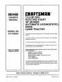
SEARS
OWNER'S
MANUAL
MODEL NO.
917.255551
[RAFTSMIIN+
12.5 HP OHV
Caution:
Read and follow
all Safety Rules
and Instructions
Before Operating
This Equipment
ELECTRIC
38"
MOWE START
AUTOMATIC (HYDROSTATIC)
DRIVE
LAWN TRACTOR
• Assembly
• Operation
• Maintenance
• Service and Adjustment
• Repair Parts
=i
i•
4.
•
i
,=
ir
J
i
Sears, Roebuck and Co., Chicago, IL 60684 U.S.A.
i|l
i im
i
i
SAFETY RULES
PLUGTO PREVENTACCIDENTALSTARTINGWHEN SETI'ING UP,TRANSPORTING,ADJUSTINGOR MAKING
CAUTION:ALWAYSDISCONNECT
SPARKPLUGWIRE ANDPLACEWIREWHEREIT CANNOTCONTACTSPARK
REPAIRS.
IMPORTANT
SAFETY STANDARDS REQUIRE OPERATOR PRESENCE CONTROLS TO MINIMIZE THE RISK OF INJU RY, YOUR UNIT IS EQUIPPED WITH SUCH
CONTROLS. DO NOT ATTEMPT TO DEFEAT THE FUNCTION OF THE OPERATOR PRESENCE CONTROLS UNDER ANY CIRCUMSTANCES.
TRAINING:
•
•
•
•
•
•
Know the controlsand how to stop quickly.Read this owner's
manual and instructionsfurnished with attachments.
Do not allow children to operate the machine. Do not allow
adults to operate it without proper instruction.
DO not carry passengers. Do not mow when children and
others are around.
DO not attempt to operate your vehicle or mower when not in
the driver's seat.
Always get on or offyourvehicle from the operator's left hand
side.
The vehicle and attachments should be stopped and inspected for damage after striking a foreign object, and the
damage should be repaired before restarting and operating
the equipment.
•
•
•
•
•
•
•
PREPARATIO N:
•
•
•
•
•
Always wear substantial footwear. Do not wear loose fitting
clothing that could get caught in moving parts.
Clear the work area of objects (wire, rocks, etc.) which might
be picked up and thrown.
Disengage all attachment clutches before attem pting to start
the engine.
Handle gasoline with care - it is highly flammable.
Use approved gasoline containers.
Never remove thefuel capofthefueltank or add gasoline
to a running or hot engine or an engine that has not been
allowed to cool for several minutes after running. Never
fill tank indoors. Always clean up spilled gasoline.
Open doors if the engine is run in the garage - exhaust
fumes are dangerous. Do not run the engine indoors.
Do not operate the mower without the entire grass catcher,
on mowers so equipped, or the deflector shield in place.
•
•
•
•
OPERATION:
o
=
•
Keep your eyes and mind on your vehicle, mower, and the
area being cut. Do not let other interests distract you.
Disengage power to attachments and stop the engine before
leaving the operator's position.
Disengage power to mower, stop the engine, and disconnect
spark plug wire(s) from spark plug(s) before cleaning, making
an adjustment, or repair. Be careful to avoid touching hot
muffler or engine components.
Disengage power to attachments when transporting or not in
use.
Take all possible precautionswhen leaving the vehicle unattended. Disengage the power take-off, lower the attach.
ments, shift into neutral, set the parking brake, stop the
engine, and remove the key.
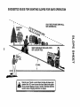
Do not stop or start suddenly when going uphill or downhill.
Mow up and down the face of slopes (not greater than 15°),
never across the face.
Reduce speed on slopes and make turns gradually to prevent
tipping or toss of control. Exercise extreme caution when
changing direction on slopes.
While going up or down slopes, place gearshift control lever
in 1st gear posit{onto negotiate the slope without stopping.
Never mow in wet or slippery grass, when tractionis unsure,
or at a speed which could cause a skid.
Stay alert for holes in the terrain and other hidden hazards.
Keep away from drop-offs.
Do not drive too close to creeks, ditches, and public highways.
Exercise special care when mowing! around fixed objectsin
order to prevent the blades from stnkingthem. Never deliberately runvehicle or mower into or over any foreign objects.
Never shift gears until vehicle comes to a stop.
Never place hands or feet under the mower, in discharge
chute, or near any moving parts while vehicle or mower is
running. Always keep clear of discharge chute.
Use care when pulling loads or using heavy equipment.
Use only approved drawbar hitch points.
Limit toads to those you can safely control.
Do notturn sharply. Use care when backing.
Use counterweightor wheel weightswhen suggested in
owner's manual.
Watch out for traffic when crossing or near roadways.
When using any attachments, never direct discharge of
material toward bystanders nor allow anyone near the vehicle while in operation.
Except for adjustments, do not operate engine if air cleaner
or cover directly over carburetor air intake is removed.
Removal of such part could create a fire hazard.
Do not change the engine governor settings or overspeed
the engine; severe damage or injury may result.
When using the vehicle with mower, proceed as follows:
Mow only in daylight or in good artificial light.
Shut the engine off when unclogging chute.
Check the blade mounting bolts for proper tightness at
frequent intervals.
Disengage power to mower before backing up. Do not mow
in reverse unless absolutely necessary and then only after
careful observation of the entire area behind the mower.
MAINTENANCE AND STORAGE
•
•
•
•
•
•
=11,
Keep the vehicle and attachments in good operating condition, and keep safety devices in place and working.
Keep all nuts, bolts, and screws tight to be sure the equipment is in safe working condition.
Never store the equipment with gasoline in the tank inside a
building where fumes may reach an open flame or spark.
Allow the engine to cool before storing in any enclosure.
To reduce fire hazard, keep the enginefree of grass, leaves,
or excessive grease. Do not clean product while engine is
running.
Do not operate without a muffler, or tamper with exhaust
system. Damaged mufflers or spark arrestors could create a
fire hazard. Inspect periodically and replace if necessary.
Under normal usage the grass catcher bag material is
subject to deterioration and wear. It should be checked
frequently for bag replacement. Replacement bags should
be checked to ensure compliance with the original
manufacturer's recommendations or specifications.
, ,m,,,
i
|
LOOK FOR THIS SYMBOL
IT MEANS - ATTENTION!I!
TO POINT OUT IMPORTANT SAFETY
PRECAUTIONS.
BECOME ALERT!!! YOUR SAFETY IS INVOLVED.
2
I
I
PRODUCT SPECIFICATIONS
CONGRATULATIONS
on your purchase of a Sears
Tractor. It has been designed, engineered and manufactured to give you the best possible dependability and
performance.
Should you experience any problem you cannot easily
remedy, please contact your nearest Sears Service
Department. We have competent, well-trained_techniclans and the proper tools to service or repair this unit.
Please read and retain this manual. The instructions will
enable you to assemble and maintain your unit properly.
Always observe the "SAFETY RULES".
MODEL
NUMBER
HORSEPOWER:
12.5
GASOLINE CAPACITY:
5 QUARTS
UNLEADED REGULAR
OIL (4.0 PINTS w/o FILTER):
(4.5 PINTS w/FILTER):
ShE 30 (or 10W-30)
WINTER: SAE 5W-30
SPARKPLUG (GAP.030 IN.):
CHAMPION RC-12YC
VALVE CLEARANCE:
INTAKE .0015/.0030 IN.
EXHAUST .0020/.0035 iN.
GROUND SPEED:
FORWARD: 0-5.5 MPH
REVERSE: 0-2.2 MPH
TIRE PRESSURE:
FRONT: 14 PSI
REAR: 12 PSI
CHARGING SYSTEM:
15 AMPS @ 3600 RPM
BLADE BOLT TORQUE:
30-35 FT. LBS.
917.255551
SERIAL
NUMBER
DATE OF PURCHASE
THE MODELAND SERIAL NUMBERS WILL BE FOUND
ON A PLATE UNDER THE SEAT.
YOU SHOULD RECORD BOTH SERIALNUMBER AND
DATE OF PURCHASE AND KEEP IN A SAFE PLACE
FOR FUTURE REFERENCE.
MAINTENANCE
WARNING: This unitis equipped with an internal combustion engine and should not be used on or near any unimproved forest-covered, brush-covered or grass-covered
land unless the engine's exhaust system is equipped with
a spark arrester meeting applicable local or state laws (if
any). lfa spark arrester is used, it should be maintained in
effective working order by the operator.
AGREEMENT
A Sears Maintenance Agreement is available on this product. Contact your nearest Sears store for details.
CUSTOMER RESPONSIBILITIES
•
Read and observe
•
Followa regular schedule in maintaining, caring for and
using your unit.
Follow the instructions
under "Maintenance"
and
"Storage" sections of this owner's manual.
•
in the state of California the above is required by law
(Section 4442 of the California Public Resources Code).
Other states may have similar laws. Federal laws apply on
federal lands. A spark arrester for the muffler is available
through your nearest Sears Authorized Service Center
(See REPAIR PARTS section of this manual).
the safety rules.
LIMITED TWO YEAR WARRANTY ON ELECTRIC START RIDING EQUIPMENT
For two years from date of purchase, when this riding equipment is maintained, lubricated, and tuned up according to the
operating and maintenance instructions in the owner's manual, Sears will repair free of charge any defect in material or
workmanship.
This Warranty does not cover:
•
Tire replacement or repair caused by punctures from outside objects (such as nails, thorns, stumps, or glass).
•
Expendable items which become worn during normal use, such as blades, spark plug, air cleaners and belts.
•
Repairs necessary because of operator abuse or negligence, including bent crankshafts and the failure to maintain the
equipment accordingto the instructions contained in the owner's manual.
•
Riding equipment used for commercial or rental purposes.
FULL 90 DAY WARRANTY
ON BA'I-rERY
For 90 days from date of purchase, if any battery includedw_ththis ridingequipment proves defective in material or workmanship
and our testing determines the battery will not hold a charge, Sears will replace the battery at no charge.
WARRANTY SERVICE IS AVAILABLE BY CONTACTING THE NEAREST SEARS SERVICE CENTER/DEPARTMENT
UNITED STATES. THIS WARRANTY APPLIES ONLY WHILE THIS PRODUCT IS IN USE IN THE UNITED STATES.
This Warranty gives you specific legal rights, and you may also have other rightswhich vary from state to state.
SEARS,
ROEBUCK
AND CO., Di731CR-W
3
SEARS TOWER,
CHICAGO,
IL 60684
IN THE
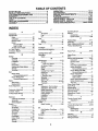
TABLE OF CONTENTS
SAFETY RULES ............................................................ 2
PROD UCT SPEC! FICATIONS ....................................... 3
CUSTOMER RESPONSIBILITIES ................................ 3
WARRANTY ................................................................... 3
TABLE OF CONTENTS ................................................. 4
INDEX ............................................................................. 4
TRACTOR ACCESSORIES ........................................... 5
ASSEMBLY ............................................................... 7-9
OPERATION ........................................................... 10-13
MAINTENANCE ...................................................... 14-18
SERVICE AND ADJUSTMENTS ............................ 19-26
STORAGE .................................................................... 27
TROUBLES HOOTIN G ............................................ 28-29
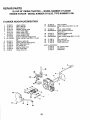
REPAIR PARTS - TRACTOR ................................. 32-47
REPAIR PARTS - ENGINE ..................................... 48-53
PARTS ORDERING/SERVICE ................... BACK PAGE
INDEX
A
Accessodes ............................................ 5
Adjustments:
Brake ........................................... 22
Carburetor ................................... 26
Electric Clutch ............................. 21
Mower
Fro ntoTo-Back ........................ 20
Side-To-Side .......................... 19
Throttle Control Cable ................. 26
Air Filter, Engine ................................. 17
Air Screen, Engine ............................. 17
Assembly ........................................... 7-9
B
Battery:
Charging ........................................ 8
Cleaning ...................................... 15
Installation ..................................... 9
Levels ....................................... 6,15
Preparation .................................... 8
Starting with Weak Battery .......... 24
Storage ........................................ 27
Terminals .................................... 15
Belt:
Motion Drive
R emoval/Replacement ........... 22
Mower Blade Drive
Removal/Repfacement ........... 21
Blade:
Sharpening .................................. 15
Replacement ............................... 15
Brake Adjustment ............................... 22
C
Carburetor Adjustment ....... :............... 26
Controls, Tractor ................................. 10
Cuffing Height, Mower ........................ 11
E
Electrical:
Interlocks and Relays .................. 24
Schematic ................................... 31
Wiring Diagram ............................ 32
Engine:
Air Filter ....................................... 17
Air Screen ................................... 17
Cooling Fins ................................ 17
Oil Change .................................. 16
Oil Level ................................. 12,16
Oil Type ....................................... 16
Preparation .................................. 12
Repair Parts ........................... 48-53
Starting ........................................ 13
Storage ........................................ 27
F
Filter:
Air Cleaner .................................. 17
Fuel ............................................. 18
Oil ................................................ 18
Fuel:
Type ............................................ 12
Storage ........................................ 27
Fuse .................................................... 24
H
Headlights .......................................... 24
Hood Removal/Installation.................. 25
L
Leveling Mower Deck .................... 19-20
Lubrication:
Chart ............................................ 14
M
Maintenance .................................. 14-18
Air Filter ....................................... 17
Foam Pre-cleaner ................... 17
Air Screen, Engine ...................... 17
Battery ......................................... 15
Blade ........................................... 15
Cooling Fins, Engine.................... 17
Engine Oil .................................... 16
Fuel Filter .................................... 18
LubricationChart ......................... 14
Schedule ..................................... 14
Spark Plugs ................................. 17
Tire Care ............................. 8,15,23
Transaxle ..................................... 16
Mower:
Adjustment, Front-to-Back........... 20
Adjustment, Side-to-Side ............. 19
Blade Sharpening ........................ 15
Blade Replacement ..................... 15
Cutting Height .............................. 11
Installation ................................... ! 9
Operation ..................................... 12
Removal ...................................... 19
Mowing Tips ....................................... 13
Muffler ................................................. 17
Spark Arrester .......................... 3,36
O
Oil:
Cold Weather Conditions ....... 12,16
Engine ......................................... 16
Filter ............................................ 18
Operation ....................................... 10-13
Storage ...............................................
4
27
Operating Mower ............................... 12
Options:
Accessories ................................... 5
Spark Attester .......................... 3,36
P
Parking Brake ................................ 10-11
Parts Bag .............................................. 6
Parts, Replacement/Repair ........... 32-53
Product Specifications........................... 3
R
Repair Parts .................................. 32-53
S
Safety Rules ......................................... 2
Seat ...................................................... 8
Service and Adjustments .............. 19-26
Carburetor ................................... 26
Electric Clutch ............................. 21
Fuse ............................................ 24
Hood Removal/Installation .......... 25
Motion Drive Belt
Removal/Replacement ........... 22
Mower Blade DriVe Belt
Removal/Replacement ........... 21
Mower Adjustment
Front- to-Back ........................ 20
Side.to-Side ............................ 19
Mower Removal!Installation ........ 19
Motion Control Lever ................... 23
Tire Care ............................. 8,15,23
Slope Guide Sheet ............................. 55
Spark Plugs ........................................ 17
S pecifications ....................................... 3
Starting the Engine ............................. 13
Steering Wheel ................................ 7,23
Stopping the Tractor ........................... 11
Storage ............................................... 27
T
Throttle Control Cable
Adjustment .................................. 26
Tires ...................................................8,15,23
Trouble Shooting Chart .................. 28-29
Transax[e:
Maintenance ................................ 16
Repair Parts ........................... 44-47
W
Warranty ............................................... 3
Wiring Diagram ................................... 32
Wiring Schematic ............................... 31
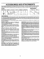
ACCESSORIES
i
iiii
AND ATTACHMENTS
i ii
These accessories and attachments were available when the unit was purchased. They are atso available at most Sears retail outlets,
catalog and service centers. Most Sears stores can order these items for you when you provide the model number of your tractor.
ENGINE
MAINTENANCE
,,L
SPARK PLUG
MUFFLER
AIR FILTER
GAS CAN
ENGINEOIL
STABILIZER
BLADES
BELTS
PERFORMANCE
Sears offers a wide variety of attachments that fit your vehicle. Many ofthese are listed below with brief explanations of how they can help
you. This listwas current at the time of publication;however, itmay change in futureyears - more attachments may be added, changes may
be made inthese attachments, or some may no longerbe available orfltyour model. Contact your nearest Sears store for the accessories
and attachments that are available for your unit.
Most of these attachments do not require additional hitches or conversion kits (those that do are indicated) and are designed for easy
attaching and detaching.
SNOW BLADEfor snow removal only. 14-inch high, 42-inch wide
PERMANEX BAGGER lets you collect grass clippings and
blade clears 38 inchpath when angled leftor right. Raises, lowers
leaves for a healthier, neater looking lawn. Two Permanex
with side lever. Adjustable skids; replaceable, reversible scraper
containers hold 30-gallon plastic bags.
bar. (Use withtire chains, wheel weights, or rear drawbar weight.)
LAWN SWEEPERS let you collect grass clippings and leaves.
SNOW'rHROWER has 40-inch swath. Drum-type auger handles
LAWN VACS for powerful collectionsof heavy grass clippings
powdery and wet!heavy snow. Mounts easily with simple pin
and leaves. Wand attachment to pick up debris in hard-to-reach
arrangement. Discharge chute adjusts from tractor seat. 6-inch
p[aces.
diameter spout discharges snow 10 to 50 feet. Lift controlledat
tractor seat. (Use with chains, wheel weights, or rear drawbar
CARTS make hauling easy. Variety of sizes available.
weight.)
ROLLER for smoother lawn surface. 36-inch wide, 18 inch
TIRE CHAINS are heavy duty; closely spaced extra-large cross
diameterwater-tight drum holdsupto3901bs, ofweight. Rounded
links give smooth ride, outstanding traction.
edges prevent harm to tuff. Adjustable scraper automatically
cleans drum.
WHEEL WEIGHTS for rear wheels provide needed traction for
snow removat or dozing heavy materials. In pairs. (30 Ibs. each.)
SPREADER/SEEDERS make seeding,fertilizing, and weed killing easy. Broadcast spreaders are also useful for granular deTRACTOR CAB has heavy duty vinyl fabric over tubular steel
icers and sand.
frame, ABS plastic top; clear plastic windshield offers 360 degree
CORING AERATOR takes small plugs out of soil to allow moisvisibility. Hinged metal doors with catch. Keeps operator warm
and dry. Remove vinyl and windshields for use as sun protector
ture and nutrients to reach grass roots. 36-inch swath. 24
in summer.
hardened steel coring tips. 150 lb. capacity weight tray.
AERATOR promotes deep root growthfor a healthy fawn. Tapered 2.5" steel spikes mounted on 10-in. diameter discs puncture holes in soil at close intervals to let moisturesoak in. Steel
weight tray for increased penetration.
Optional accessories for tractor cab: tinted/tempered solid safety
glass windshield with hand operated wiper; 12-volt amber caution
light for mounting on cab top.
TRACTOR COVER protects tractor from weather. Made of
Evolution 3 fabric (water-repellent, extremely breathable, light
weight, soft, non-abrasive, pliable in all temperatures, durable,
stain/tear/puncture resistant, will not shrink or stretch).
DETHATCHER loosenssoil andflipsthatch and matted leaves to
lawn surface for easy pick up. Twenty springtine teeth. Useful
to prepare bare areas for seeding. Available for front or rear
mounting.
SPRAYERS use 12-volt DC electric motor that connects to the
tractor battery or other 12-volt source. Includes booms for
automatic spraying when pulling, and hand held wand for spot
spraying. Wand has adjustable spray pattern. For appiying
herbicides, insecticides, fungicides, and liquidfertilizers.
5
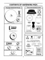
CONTENTS
OF HARDWARE
PACK
iiiii i
Parts Bag contents
shown full size
Parts packed separately
H
i
Seat
Metal
Screws
(2)
Sheet
#10-16 x 1/2
O
in carton
m
Battery acid
(1) Locknut 1/2 - 20
(1) 2-3/8" Dia. Washer
Wheel
Battery
i
I
I
Steering
"1
I
Steering
Boot
(4) Hex Bolts 5/16-18 x 1
Owner's Manual
Parts Bag
%
Steering
Bushing
Wheel
Steering
Insert
(2) Keys
(4) Spacers
(2) Battery Carriage Bolts 1/4-20 x 7-1/2
1IIII1
IIIII
IIIlllllll!U
(2) Hex Bolts 1/4 - 20 x 3/4
Steering Wheel
Adapter
@
Terminal Guard
(2) Hex Nuts 1/4 - 20
i
(2) Washers 9/32 x 5/8 x 16 Ga. (2) Lockwashers 1/4
s
15 ° Slope Sheet
(2) Wing Nuts 1/4 - 20
6
Battery Caps
and Instructions
ASSEMBLY
TOOLS
REQUIRED
FOR ASSEMBLY
INSERT
1/2 - 20 HEX LOCI
A socket wrench set will make assembly easier. Standard
wrench sizes are listed.
(1) 5/16" wrench
(1) 3/4" wrench
(2) 7/16" wrenches
Tire pressure gauge
(I) 1/2" wrench
(1) 9/16" wrench
Screwdriver
Utility knife
2-1/4" DIA.
When right or left hand is mentioned in this manual, it
means when you are in the operating position (seated
behind the steering wheel).
TO REMOVE UNIT FROM CARTON
STEERING
BUSHING
UNPACK CARTON
•
Remove all accessible loose parts and parts cartoons
from carton (See page 6).
•
Cut, from top to bottom, all four corners of carton and
lay panels flat.
•
Check for any additional loose parts or cartons and
remove.
SLOT
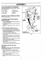
ATTACH
STEERING
WHEEL (See Fig. 1)
•
Slide the steering bushing over the steering shaft.
•
•
STEERING SHAFT
(SHIPPING
POSITION)
Raise steering shaft forward until screw holes in dash
lin@up with steering bushing. Install two (2) sheet
metal screws and tighten securely.
Position steering boot over steering shaft.
•
Place tabs of steering boot over slots in dash and push
down to secure.
•
Siide steering wheel adapter onto upper steering shaft.
•
Position front wheels of the tractor so they are pointing
straight forward.
•
Position steering wheel so cross bars are horizontal
(left to right) and slide onto adapter.
•
•
Assemble large flatwasher and 1/2-20 hex Iocknut and
tighten securely.
Snap insert into center of steering wheel.
°
Remove protective plastic from tractor hood and grill.
BEFORE ROLLING
STEERING SHAFT
(ASSEMBLY POSITION)
FIG. 1
UNIT OFF SKID
(See Fig. 6)
IMPORTANT; CHECK FOR AND REMOVE ANY
STAPLES IN SKID THAT MAY PUNCTURE TIRES WHERE
UNIT IS TO ROLL OFF SKID.
•
•
•
.
•
Raise attachment lift lever to its highest position.
Release parking brake by depressing clutch/brake
pedal.
Pull freewheel knob up to disengage transmission.
Roll unit backwards off skid.
Remove banding holding discharge guard up against
tractor.
7
ASSEMBLY
HOW TO SET UP YOUR
TRACTOR
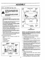
INSTALL SEAT (See Fig. 3)
Seat position should be adjusted forward or backward so
thatthe operatorcan comfortably reach clutch/brakepedal
and safely operate the tractor.
•
Remove cardboard packing on seat pan.
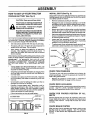
PREPARE BATTERY (See Fig. 2)
CAUTION: Wear eye and face shield.
Wash hands or clothing immediately if
accidentally in contact with battery acid.
•
Do not smoke. Fumes from charged
battery acid are explosive.
•
Read the Instructions included with the
batteryvent caps. Alwayswear gloves,
clothing and goggles to protect your
hands, skin and eyes.
•
Your unit has a battery chargingsystem which issufficient
for normal use. However, periodic charging of the battery
with an automotive charger will extend its life.
•
•
See instructions packed with vent caps in parts bag.
•
•
Flit battery with acid. Flit each cell until it reaches the
bottom of the vent wells. Do not overfill.
•
Allow battery to stand and settle for at least thirty
minutes. After standing, check the level of acid. If
below the vent wells, add more acid until the correct
level is reached.
Release R.H. slide on seat pan bypullingout onhandle
and slidingit to the rear positionexposingseat mounting holes from bottom. Slide L.H. slide to same rear
position,
Mount rear of seat on slides using mountinghardware
shown, Be sure to install spacers between seat and
seat slides with cupped side of spacer up towardseat.
Pullout on adjustment handle and slideseat all the way
forward.Installfrontmounting boltsand spacers.Tighten
all mounting bolts securely.
Lower seat into operating position and sit on seat.
Press clutch/brake pedal all the way down. If operating
position is not comfortable, adjust seat.
To adjust seat: Grasp adjustment handle and pull out,
slide seat to desired position and release handle.
SPACERS
_
_
_
SEAT
While battery is standing (after adding acid) and later, while
battery is being charged, continue with assembly of un;t.
IMPORTANT:
TO MAXIMIZE THE LIFE OF YOUR
BATTERY, IT IS NECESSARY THAT THE BATTERY BE
CHARGED BEFORE USE. FAILURE TO CHARGE
BATTERY CAN RESULT IN A SHORTENED BATTERY
LIFE.
•
•
•
•
•
•
Charge battery at a rate of 6 amperes for 1 hour. Use
a 12 volt battery charger. Observe all safety precautions
required for battery charging.
FIG. 3
CHECK TIRE PRESSURE
Check the acid level after the battery is charged. If the
acid has fallen below the correct level, add distilled or
iron free water.
The tires on your unit were overinf[ated at the factory for
shipping purposes. Correct tire pressure is important for
best cutting performance.
Install the vent caps to coverthe vent wells. Wash the
top of the battery w_h water to remove any acid, then
wipe dry.
•
Check battery case for leakage to make sure that no
damage has occurred in handling.
Dispose of excess battery acid. Neutralize acid for
disposal by adding it to four inches of water in a five
gallon plastic container. Stir with a wooden or plastic
paddle while adding baking soda until the addition of
more soda causes no more foaming.
Follow instructions on how to install battery.
CHECK DECK LEVELNESS
For best cutting results, mower housing should be properly
leveled. See "TO LEVEL MOWER HOUSING" in the
Service and Adjustments section of this manual.
CHECK
BELTS
C UT AWAY V lEW
FOR PROPER
POSITION
OF ALL
See the figures that are shown for replacing motion and
mower blade drive belts in the Service and Adjustments
section of this manual. Verify that the belts are routed
correctly.
VENT WELL
BATTERY
CELL ACID
LEVEL
FIG. 2
Reduce tire pressure to PS! shown in "PRODUCT
SPECIFICATIONS" on page 3 of this manual.
CHECK BRAKESYSTEM
8
After you learn how to operate your tractor, check to see
that the brake is properly adjusted. See "TO ADJUST
BRAKE" in the Service and Adjustments section of this
manual.
ASSEMBLY
INSTALL BATTERY
&
(See Figs. 4 & 5)
WING
NUT
TERMINAL GUARD
ACCESS
DOOR
CAUTION: Do not short battery terminals. Before installing battery, remove
metal bracelets, wristwatch bands,
rings, etc.
Positive terminal must be connected
first to prevent sparking from accidental grounding.
•
•
•
•
•
•
•
•
•
Lift seat to raised position.
Lower battery into fender well with battery terminals
toward front of unit. Make sure battery rests in battery
tray.
Be sure battery drain tube has not come loose and is
securely attached to drain in battery tray.
First connect RED battery cable to positive (+) battery
terminal with hex bolt, flat washer, lock washer and hex
nut as shown. Tighten securely.
Connect BLACK grounding cable to negative (-) battery terminal with remaining hex bolt, flat washer, lock
washer and hex nut. Tighten securely.
BATTERY
BOLT
KEY
HOLE
Slide the two battery bolts throughthe terminal guard
and start the wing nuts onto the threads.
Position terminal guard over the battery as shown,
lower bolts into key holes and slide square shafts of
bolts into slots of key holes.
BATTERY
DRAIN TUBE
BATTERY
TRAY
FIG. 5
,/'CHECKLIST
BEFORE YOU OPERATE AND ENJOY YOUR NEW
TRACTOR, WE WISH TO ASSURE THAT YOU RECEIVE
THE BEST PERFORMANCEAND SA TISFACTION FROM
THIS QUALITY PRODUCT.
Tighten wing nuts by hand making sure battery bolts
remain in slots of the key holes in the battery support.
Be sure terminal access doors are closed.
Use terminal access doors for:
PLEASE REVIEW THE FOLLOWING CHECKLIST:
•
Inspection for secure connections (to tighten hardware)
/
•
Inspection for corrosion
,/
•
Testing battery
Battery is properly prepared and charged.
1 hour at 6 amps).
•
•
jumping (if required)
Periodic charging
,/
Seat is adjusted comfortably and tightened securely.
,/
All tires are properly inflated. (For shipping purposes,
the tires were over-inflated at the factory).
(Minimum
#" Be sure mower deck is properly leveled side-to-side/
front-to-rear for best cutting results. (Tires must be
properly inflated for leveling).
#" Check mower and drive belts. Be sure they are routed
properly around pulleys and inside all belt keepers.
POSITIVE (+)
TERMINAL
POSITIVE (RED)
CABLE
All assembly instructions have been completed.
,/" No remaining loose parts in carton.
NEGATIVE ( - )
TERMINAL
N EGAT/VE
(BLACK)
FLATWASHERS
CABLE
V" Check wiring. See that all connections are still secure
and wires are properly clamped.
WHILE LEARNING HOW TO USE YOUR TRACTOR, PAY
EXTRA A TTENTION TO THE FOLLOWING IMPORTANT
ITEMS:
/
,/
HEX NUT
LOCK WASHERS
Engine oil is at proper level.
Fuel tank is filled with fresh, clean, regular unleaded
gasoline.
,/" Become familiar with all controls - their location and
function. Operate them before you start the engine.
HEX NUT
FIG. 4
/
9
Be sure brake system is in safe operating condition.
OPERATION
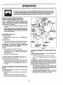
KNOW YOUR TRACTOR
READ THIS OWNER'S
MANUAL AND SAFETY RULES BEFORE OPERATING
YOUR TRACTOR
Compare the illustrationswith yourtractorto familiarize yourselfwith the locationsof various controlsand adjustments. Save
this manual for future reference.
ATTACHMENT
CLUTCH SWITCH
UGHT SWITCH
AMMETER
LIFT LEVER PLUN(_ER
THRO'B'L_CHOKECONTROL
CLUTCH!BRAKE
PEDAL
LEVER
BRAKE LEVER
FREEWHEEL CONTROL
CONTROLLEVER
HEIGHT ADJUSTMENT
KNOB
FIG. 6
Sears tractors conform to the safety standards of the American National Standards Institute.
A'I-rACHMENT CLUTCH SWITCH - Used to engage the
mower blades or other attachments mounted to your tractor,
ATTACHMENT LIFT LEVER - Used to raise and lower the
mower deck or other attachments mounted to your tractor.
LIFT LEVER PLUNGER - Used to release attachment lift
lever when changing its position.
rection of the tractor.
LIGHT SWITCH - Turns the headlights on and off.
PARKING BRAKE LEVER - Locks clutch/brake pedal into
the brake position.
THRO'B'LEiCHOKE CONTROL - Used for starting and
controlling engine speed.
FREEWHEEL CONTROL - Disengages transmission for
pushing or slowly towing the tractor with the engine off.
AMMETER - Indicates charging (+) or discharging (-) of
batte_.
INDICA'I;OR LIGHTS - Indicates clutch/brake pedal engagement, attachment engagement, low oil pressure,and
low fuel level.
HEIGHTADJUSTMENT KNOB - Usedto adjust themower
cutting height.
CLUTCH/BRAKE PEDAL - Used for declutching and
braking the tractor and starting the engine.
IGNITION SWITCH - Used for starting and stopping the
engine.
MOTION CONTROL LEVER - Selects the speed and di-
10
OPERATION
The operation of any tractorcan result inforeign objectsthrown intothe eyes, whichcan resuft
in severe eye damage. Always wear safety glasses or eye shieldswhile operating your tractor
or performing any adjustments or repairs. We recommend Wide Vision Safety Mask for over
the spectacles or standard safety glasses, available at Sears Retail or Catalog Stores.
HOW TO USE YOUR TRACTOR
CLUTCH SWITCH
"ENGAGED"
POSITION
MOTION
CONTROL
LEVER
IGNITION
KEY
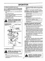
TO SET PARKING BRAKE (See Fig. 7)
Your unit is equipped with an operator presence sensing
switch. When engine is running, any attempt by the
operator to leave the seat without first setting the parking
brake will shut off the engine.
•
Depress clutch/brake pedal intofull "BRAKE" position
and hold.
•
Place parking brake lever in "ENGAGED" position and
release pressure from clutch/brake pedal. Pedalshould
remain in "BRAKE" position. Make sure parking brake
will hold vehicle secure.
STOPPING
(See Fig. 7)
MOWER BLADES •
Move attachment clutch switch to "DISENGAGED"
position.
GROUND DRIVE ,
PARKING BRAKE
"ENGAGED =
POSITION
Depress clutch/brake pedal intofull "BRAKE" position.
"BRAKE"
POSITION
•
Move motion control lever to "NEUTRAL" position.
iMPORTANT:
THE MOTION CONTROL LEVER DOES
NOT RETURN TO "NEUTRAL" POSITION WHEN THE
CLUTCH/BRAKE PEDAL IS DEPRESSED.
ENGINE -
"DISENGAGED"
POSITION
CLUTCH/BRAKE
PEDAL "DRIVE"
POSITION
HEIGHT
ADJUSTMENT
KNOB
FIG. 7
•
Move throttle controlto "SLOW" position,
•
Turn ignition key to "OFF" position and remove key.
Always remove key when leaving vehicle to prevent
unauthorized use.
TO ADJUST MOWER CUTTING HEIGHT (See
Fig. 7)
•
Never use choke to stop engine,
The cuttingheight is controlled by turning the height adjustment knob in desired direction.
TO USE THROTI'LE
CONTROL
(See Fig. 7)
Always operate engine at full throttle.
* Operating engine at less than full throttle reduces the
battery charging rate and the engine cooling air flow.
,
Full throttle offers the best bagging and mower performance.
TO MOVE FORWARD AND BACKWARD
Fig. 6)
•
Turn knob clockwise (r_) to raise cutting height.
•
Turn knob counterclockwise
height.
The direction and speed of movement is controlledby the
motion control lever.
•
Start tractor with motion control lever in "NEUTRAL"
position.
Release parking brake and clutch/brake pedal.
•
Slowly move motion control lever to desired position.
[ower cutting
The cutting height range is approximately 1-1/4" to 3-3/4".
The heights are measured from the ground to the blade tip
with the engine not running. These heights are approximate and may vary depending upon soil conditions, height
of grass and types of grass being mowed.
•
The average lawn should be cut approximately 2-1/2
inches during the cool season and over 3 inches during
hot months. For healthier and better looking lawns,
mow often and after moderate growth.
•
For best cutting performance, grass over 6 inches in
height should be mowed twice. Make the first cut
relatively high; the second to desired height.
(See
•
(_'_)to
11
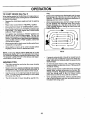
OPERATION
TO OPERATE
MOWER
•
(See Fig. 8)
If stopping is absolutely necessary, push clutch/brake
pedal quickly to brake position and engage parking
brake.
Your unit is equipped with an operator presence sensing
switch. Any attempt by the operatorto leave the seat with
the engine runningand the attachment clutchengaged will
shut off the engine.
•
Select desired height of cut, using height adjustment
knob.
•
Move motion control lever to "NEUTRAL" position.
IMPORTANT: THE MOTION CONTROL LEVER DOES
NOT RETURN TO "NEUTRAL" POSITION WHEN THE
CLUTCH/BRAKE PEDAL IS DEPRESSED.
•
Lower attachment lift lever.
•
•
Engage mower by pulling attachment clutch switch up
and out to "ENGAGED" position.
TO STOP MOWER- Move attachment clutch switch to
"DISENGAGED" position.
Raise attachment lift lever.
•
To restartmovement, slowlyrelease parkingbrake and
clutch/brake pedal.
Slowly move motion control lever to slowest setting.
•
Make all turns slowly.
•
•
TO TRANSPORT
without either the entire grass catcher,
CAUTION:
on
mowers Do
so not
equipped,
operate or
thethe
mower
discharge guard in place.
•
Raise attachment lift control to highest position.
•
When pushing or towing your unit, be sure motion
control lever is in "NEUTRAL" position.
•
Pull freewheel control knob up to disengage transmission (See Fig. 6).
•
Do not push or tow unit at more than five (5) MPH.
BEFORE
ATTACHMENT CLUTCH
SWITCH "DISENGAGED"
POSITION
POSITION
CHECK
•ATTACHMENT
UFT LEVER
HIGH POSITION
STARTING
ENGINE
THE ENGINE
OIL LEVEL
(See Fig. 16)
•
The engine in your unit has been shipped, from the
factory, already filled with summer weight oil.
•
•
Check engine oil with unit on level ground.
Unthread and remove the oil fill cap/dipstick; wipe oil
off. Reinsert the dipstick into the tube and rest the oil fill
cap on the tube. Do not thread the cap onto the tube.
Remove and read oil level. If necessary, add oil until
"FULL" mark on dipstick is reached. Do not overfill.
•
For cold weather operation you should change oil for
easier starting (see "OIL VISCOSITY CHART" in the
Maintenance section of this manual).
•
To change engine oil, see the Maintenance section in
this manual,
POSITION
ADD GASOLINE
°
Fill fuel tank. Use fresh, clean, regular unleaded
gasoline. (Use of leaded gasoline will increase carbon
and lead oxide deposits and reduce valve life).
IMPORTANT: WHEN OPERATING IN TEMPERATURES
BELOW 32 ° (0°C), USE FRESH, CLEAN WINTER GRADE
GASOLINE TO HELP INSURE GOOD COLD WEATHER
STARTING.
R.R.
RUNNER
WARNING: Experience indicates that alcohol blended
fuels (called gasohol or using ethanol or methanol) can
attract moisture which leads to separation and formation of
acids during storage. Acidic gas can damage the fuel
system of an engine whiie in storage. To avoid engine
problems, the fuel system should be emptied before storage of 30 days or longer. Drain the gas tank, start the
engine and let it run until the fuel lines and carburetor are
empty. Use fresh fuel next season. See Storage Instructions for additional information.
Never use engine or
carburetor cleaner products in the fuel tank or permanent
damage may occur.
DISCHARGE
GUARD
FIG. 8
TO OPERATE
ON HILLS
hills
with slopes
greater
15down
° and
CAUTION:
Do not
drive than
up or
do not drive across any slope,
Choose the slowest speed before starting up or down
hills.
•
Avoid stopping or changing speed on hills.
•
If slowing is necessary, move throttle control lever to
slower position.
CAUTION: Fill to bottom of gas tank
filler neck. Do not overfill. Wipe offany
spilled oil or fuel. Do not store, spill or
use gasoline near an open flame.
12
OPERATION
ruing.
Drive so that clippings are discharged onto the area
that has been cut. Have the cut area to the right of the
machine. This will result in a more even distribution of
clippingsand more uniform cutting.
TO START ENGINE (See Fig. 7)
When starting engine for the first time or if engine has run
out of fuel, it will take extra cranking time to move fuel from
the tank to the engine.
•
Depress the clutch/brake pedal and set the parking
brake.
•
Place motion control lever in "NEUTRAL" position.
•
•
Move attachment clutch to "DISENGAGED" position.
Movethrottle control lever to"CHOKE" position for cold
engine start. For warm engine start, move throttle
control to "FAST" position.
•
•
•
When mowing large areas, start by turning to the right
so that clippings will discharge away from shrubs,
fences, driveways, etc. After one or two rounds, mow
in the opposite direction making left hand turns until
finished (See Fig. 9).
F
Turn ignition key clockwise to "START" position and
release key as soon as engine starts. Do not run
starter continuously for more than fifteen seconds per
minute. If engine does no_ start a_er several attempts,
move throttle control to FAST position, wait a few
minutes and try again.
When engine starts, slowly move throttle control lever
to desired running speed.
Allow engine to warm up for a few minutes before
engaging motion control or attachment clutch.
FIG. 9
NOTE: If at a high altitude (above 3000 feet) or in cold
temperatures (below 32 ° F), the carburetor fuel mixture
may need to be adjusted for best engine performance. See
"TO ADJUST CARBURETOR" in the Service and Adjustments section of this manual.
•
MOWING TIPS
If grass is extremely tall, it should be mowed twice to
reduce load and possible fire hazard from dried clipdPings. Make first cut relatively high; the second to the
esired height.
Do not mow grass when it is wet. Wet grass will plug
mower and leave undesirable clumps. Allow grass to
dry before mowing.
•
Tire chains cannot be used when the mower housing
is attached to unit.
•
•
Mower should be properly leveled for best mow!,n..g
performance. See"TO LEVELMOWER HOUSING in
the Service and Adjustments section of this manual.
Use the runner on the right hand side of mower as a
guide. The blade cuts approximately an inch outside
the runner (See Fig. 8).
The left hand side of mower should be used for trim-
•
Always operate engine atfull throttle when mowing to
assure better mowing performance and proper discharge of material. Regulate ground speed by selecting a low enough gear to give the mower cutting
performance as welt as the quality of cut desired.
•
When operating attachments, select a ground speed
that will suit the terrain and give best performance of
the attachment being used.
•
•
13
MAINTENANCE
CheckBrakeOperation
Check:FirePressure
t
If
!1/'
"Checkfor LooseI=asteners
!l/'
I_
_#'
R
Sharpen/ReplaceMowerBlades
V#'4
T
0
LubricationChart
Check'Battery
LevellRecharge
Clean Batteryand Terminals
_
_#
_
R Check Transmission Cooling
V#
I##
AdjustBlade Bett(s)Tension
Adjusi 'MotionDrive Belt(s) Tension
CheckEngine Oil Level
....
_
V _
ChangeEngine Oil
E Clean
Ai!.Filter
W #
CleanAir Screen
G
Inspect Muffler/SparkArrester . . .
N
I_ti.s
....
N
I
!_,,,
....
V#
!/2
....
I/2
I_ #
Replace Oil Filter(If equipped)
._.2
CleanEngineCoolingFins
ReplaceSpark Plug
V'2
_
ReplaceAir Filter Paper Cartridge
I##'2
V _
.
.
ReplaceFuel Filter
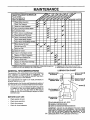
1 - Change more often when operating under a heavy load or in high ambient temperatures.
2 - Service mote often when operating in dirty or dusty conditions.
LUBRICATION
GENERAL RECOMMENDATIONS
The warrantyon thisvehicle does not cover itemsthathave
been subjected to operator abuse or negligence. To
receive fullvalue from the warranty, operator must maintain unit as instructedin this manual.
(_)SPINDLEZERK-_
Some adjustments will need to be made periodically to
properly maintain your unit.
(_)FBRE_NITN_HzEEELK"I_ I_l
CHART
_r_-
SP=NDLE
ZERK
Vl'.'-"I_FRONITN_rHzEEELK(_
)
All adjustments in the Service and Adjustments section of
this manual should be checked at least once each season.
•
Once a year you shouTd replace the spark plug, clean
or replace air filter, and check blades and belts for
wear. A new spark plug and clean air filter assure
proper air-fuel mixture and help your engine run better
and last longer.
BEFORE EACH USE
•
•
Check engine oil level.
Checkbrake operation.
•
•
Checktire pressure.
Checkfor loose fasteners.
(_)CH
EC K/ADD""
CHECqADD
PUMP FLUID
I
\ .............. /
I I
_
(_) SAE 10W30 MOTOR OIL API - SF/CC
(_
GENERAL PURPOSE GREASE
(_) REFER TO ENGINE MAINTENANCE
14
SECTION
IMPORTANT:
DO NOT OIL OR GREASE THE PIVOT POINTS
WHICH HAVE SPECIAL NYLON BEARINGS.
VISCOUS LUBRICANTS WILL ATTRACT DUST AND DIRT THAT WILL SHORTEN
THE LIFE OF THE SELF-LUBRICATING
BEARINGS.
IF YOU
FEEL THEY MUST BE LUBRICATED,
USE ONLY A DRY, POW.
DERED GRAPHITE TYPE LUBRICANT SPARINGLY.
MAINTENANCE
TRACTOR
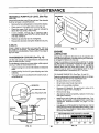
TO SHARPEN
Always observe safety rules when performing any maintenance.
BRAKE OPERATION
•
If unit requires more than six (6) feet stoppingdistance at
high speed in highest gear, than brake mustbe adjusted.
(See "TO ADJUST BRAKE" in Service and Adjustments
section of this manual).
The blade can be sharpened with a file or on a grinding
wheel. Do not attempt to sharpen while on the mower.
To check blade balance, drive a nail intoa beam orwall.
Leave about one inch of the straight nail exposed.
Place center hole of blade over the head of the nail. If
blade is balanced, it should remain in a horizontal
position. If either end of the blade moves downward,
sharpen the heavy end until the blade is balanced.
•
TIRES
•
Maintain proper air pressure in all tires (See "PRODUCT SPECIFICATIONS" on page 3 of this manual).
Keep tires free of gasoline, oil, or insect control chemicals which can harm rubber.
•
•
BLADE (See Fig. 11)
Care should be taken to keep the blade balanced. An
unbalanced blade witlcause excessive vibration and eventual damage to mower and engine.
CENTER
HOLE
Avoid stumps, stones, deep ruts, sharp objects and
other hazards that may cause tire damage.
BLADE CARE
For best results mower blades must be kept sharp. The
blades can be sharpened with a file or On a grinding wheel.
We suggest they be sharpened or replaced after every 25
hours of mowing. Check blades more often if mowing in
sandy conditions.
•
Do not attempt to sharpen blades while they are on the
mower.
•
Replace bent or damaged blades.
BLADE REMOVAL
Raise mower to highest position to al!ow access to
blades.
•
Remove hex bolt, lockwasher and flatwasher securing
biade.
•
Install new or resharpened blade with trailing edge up
towards deck as shown.
•
Reassemble hex bolt, lock washer and flat washer in
exact order as shown.
•
Tighten boft securely (30-35 Ft. Lbs. torque).
BLADE
Your unithas a battery charging system which is sufficient
for normal use. However, periodic charging of the battery
with an automotive charger will extend it's life.
•
Acid solution level in each battery cell should be even
with bottomsofvent wells. Add onlydistilled or ironfree
water if necessary. Do not overfill
(See Fig. 10)
,
IMPORTANT;
FIG. 11
BATTERY (See Fig. 12)
BOLT
IS GRADE
5 HEAT
/
CUT AWAY VIEW
Ii
....
__'_
•
•
•
°
TO
T UUNG
_
HEX BOLT _
_
_
EDGE
UP
(GRADE S)"
Q
°
•
CAN BE IDENTIFIED BYTHREE LIN ES
ON THE BOLT HEAD AS SHOWN AT
*A
LEFT,
GRADE 5 HEAT TREATED BOLT
•
•
FIG. lO
FIG. 12
Keep battery and terminals clean.
Keep battery bolts tight.
Keep vent caps tight and small vent holes in caps open.
Recharge at 6 amperes for 1 hour.
CLEAN BATTERY AND TERMINALS -
Corrosion and dirt on the battery and terminals can cause
the battery to "leak" power.
•
Remove terminal guard.
•
Disconnect BLACK battery cable first then RED battery cable and remove battery from tractor.
•
Wash battery' with solution of four tablespoons of
baking sodatoone gallon ofwater. Be careful notto get
the soda solution into the cells.
FLANGES
LOCKWASHEr- .
_=!
TREATED.
ASSEMBLY
F
'VENT
'J_L
.
BATTERY
CELL ACID
LEVEL
MANDREL
(JACKSHAFT)
_)j_-"-
_VENTCAP
15
Rinse the battery with plain water and dry.
Clean terminals and battery cable ends with wire brush
until bright.
Coat terminals with grease or petroleum jelly.
Reinstall battery (See "INSTALL BATI'ERY" in Assembly section of this manual).
MAINTENANCE
TRANSAXLE
FASTENERS
PUMP FLUID LEVEL (See Figs.
13 & 14)
Check fluid level after every 25 hours of use. Rear drawbar
must be removed to check fluid level.
•
Remove the four (4) fasteners to remove the drawbar.
•
Clean reservoir thoroughly before removing cap.
•
•
Check for proper fluid level in reservoir (should be
above the "OIL LEVEL COLD" line).
If oil is needed, remove cap on reservoir (with a
clockwise rotation), and fill to "OlL LEVEL COLD" line
with SAE 10W30 oil.
•
•
Replace cap securely (do not overtighten).
Reassemble drawbar and tighten fasteners securely.
FASTENERS
/
V-BELTS
DRAWBAR
Check V-Belts for deterioration and wear after 100 hours
and replace if necessary. The motion and mower blade
drive belts are not adjustable. Replace belts if they begin to
slip from wear.
TRANSMISSION
COOLING
FIG. 14
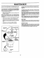
ENGINE
LUBRICATION
Change the oil after the first two hours of operation and
every50hours thereafter or at least once a year ifthe tractor
is not used for 50hours in one year.
Check the crankcase oil level before starting the engine
and after each five (5) hours of continuous use. Add SAE
30W motor oil or equivalent. Tighten oil fill cap/dipstick
securely each time you check the oil level. SAE 5W-30
motor oil may be used to make starting easier in areas
where temperature is consistently 32 ° F or lower.
(See Fig. 13)
The fan and cooling fins of transmission should be kept
clean to assure proper cooling.
Do not attempt to clean fan or transmission while engine is
running or while the transmission is hot.
•
Inspect cooling fan to be sure fan blades are intact and
clean.
•
Inspect cooling fins for dirt, grass clippings and other
materials.
•
Thoroughly clean the cooling fins with a cloth, brush, or
compressed air.
TO CHANGE ENGINE Of L (See Figs. 15 and 16) Determine temperature range expected before oil change,
All oil must meet AP[ service classification SG.
•
Be sure vehicle is on level surface.
•
•
Oil will drain more freely when warm.
Catch oil in a suitable container.
°
Remove oil fill dipstick. Be careful not to allow dirt to
enter the engine when changing oil.
"OIL LEVEL COLD" LINE
•
•
COOUNG FAN
•
Remove drain plug.
After oil has drained completely, replace oil drain plug
and tighten securely.
Refill engine with oil through oil fill dipstick tube. Pour
slowly. Do not overfill. For approximate capacity see
"PRODUCT SPECIFICATIONS" on page 3 of this
manual.
RESERVOIR
"OIL LEVEL HOT" LINE
Use gauge on oil fill dipstick for checking level. Do not
thread the cap onto the tube when taking reading. Keep
oil at "FULL" line on dipstick. Tighten cap onto the tube
securely when finished.
COOLING
FINS
RECOMMENDED SAE VISCOSITY GRADES
l,I,l,l
4 EE
-20 °
FIG. 13
16
0°
32 °
FIG, I5
60°
80 °
100°
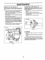
MAINTENANCE
AIR FILTER FOAM PRE-CLEANER
CLEAN AIR INTAKE/COOLING
Fig. 16)
(See Fig. 16)
Your engine will not run properly and may be damaged by
using a dirty air filter. Clean the foam pre-cleaner element
after every 25 hours of operation, more often if tractor is
used in very dusty, dirty conditions.
•
Remove knob and cover.
To insure proper cooling, make sure the grass screen,
cooling fins, and other external surfaces of the engine are
kept clean at all times.
Every 100 hours of operation (more often under extremely
dusty, dirty conditions), remove the blower housing and
other cooling shrouds. Clean the cooling fins and external
surfaces as necessary. Make sure the cooling shroudsare
reinstalled.
•
Remove foam pre-cleaner element by sliding it off of
the paper cartridge.
NOTE: Do not attempt to clean or oil the paper cartridge.
Replace paper cartridge once a year or after every 100
hours of operation; more often if used in very dusty or dirty
conditions.
•
Wash foam pre-cleaner in liquid detergent and water.
•
•
Wrap foam pre-cleanerin cloth and squeeze dry.
Lightly coat foam pre-cleaner with clean engine oil.
Squeeze in towel to remove excess oil. Do not saturate.
•
•
Install foam pre-cleaner over paper cartridge.
Reassemble cover and tighten knob securely.
AREAS (See
NOTE; Operating the enginewith ab!ocked grass screen,
dirty or plugged cooling fins, and/or cooling shrouds removed, will cause engine damage due to overheating.
MUFFLER
Inspect and replace corroded muffler and spark arrester (if
equipped) as it could create a fire hazard and/or damage.
SPARK PLUGS
Replace spark plugs at the beginning of each mowing
season or after every 100 hours of use, whichever comes
first. Spark plug type and gap setting is shown in "PRODUCT SPECiFiCATIONS" on page 3 of this manual.
-COVER
MR CLEANER
COVER
KNOB
NUT
FOAM
PRE-CLEANER
MR CLEANER
'BASE
AIR CLEANER
PAPER CARTRIDGE
ENGINE OIL
AND DIPS_CK
AIR INTAKE
SC
OIL DRAIN
PLUG
FIG. 16
17
MAINTENANCE
ENGINE OIL FILTER
(See Fig. 17)
IN-LINE FUEL FILTER
Replace the engine oilfilter every season or every other oil
change if the tractor is used more than 100hours in one
year.
•
Drain oil from engine crankcase ( See "TO CHANGE
ENGINE OIL" through step remove drain plug).
•
Remove oii filter drain plug located at base of 0il filter
adapter. Allow oil filter to drain.
•
Remove oil filter and wipe offfilter adapter. ReinstaJloil
filter drain plug.
•
Apply a thin coating of new engine oil to the rubber
gasket on replacement oil filter.
•
•
Install replacement oil filter on filter adapter. Turn oil
filter clockwise until rubber gasket contacts the filter
adapter, then tighten filter an addiUonal 1/2 turn.
Fill crankcase with new oil ( See "TO CHANGE ENGINE OIL" in this section of this manual). For approximate capacity see "PRO DUCT SPECIFICATIONS" on
page 3 of this manual.
•
Start the engine and check for oll leaks. Correct any
leaks before placing engine into full operation.
(See Fig. 18)
Fuelfilter shouldbe replaced once each season. Iffuelfilter
becomes clogged, obstructingfuel flow to carburetor, replacement is required.
•
With engine cool, remove filter and plug fuel line
sections.
•
Place new fuel filter in position in fuel line.
•
Be sure there are no fuel line leaks and clamps are
properly positioned.
•
Immediately wipe up any spilled gasoline.
FUEL FILTER
OIL FILTER
CLEANING
•
Clean engine, battery, seat, finish, etc. of all foreign
matter.
•
Keep finished surfaces and wheels free of all gasoline,
oil, etc.
•
Protect painted surfaces with automotive type wax.
We do not recommend using a garden hose to clean your
unit unless the electrical system, muffler, air filter and
carburetor are covered to keep water out, Water in engine
can result in a shortened engine fife.
OIL FILTER
DRAIN PLUG
FIG. 17
18
i
i
SERVICE AND ADJUSTMENTS
i
CAUTION:
BEFORE PERFORMING ANY SERVICE OR ADJUSTMENTS:
Depress clutch/brake pedal fully and set parking brake.
Place motion control lever in =NEUTRAL" position.
•
Place attachment clutch in =DISENGAGED" position.
•
•
•
Turn ignition key "OFF" and remove key.
Make sure the blades and all moving parts have completely stopped.
Disconnect spark plug wire from spark plug and place wire where it cannot come in contact with
plug.
TRACTOR
TO INSTALL MOWER
TO REMOVE
•
•
•
Raise attachment lift lever to its highest position.
Turn height adjustment knob to lowest setting.
Slide mower under tractor with discharge guard to right
side of tractor.
•
MOWER (See Fig. 19)
Mower will be easier to remove from the right side of unit.
•
Remove mower blade drive belt from electric clutch
pulley only (See "TO REPLACE MOWER BLADE
DRIVE BELT" through step removingbeltfrom electric
clutch pulley),
•
Pull retainer springs out of rear suspension trunnions.
Remove rear suspension trunnionsfrom lift brackets.
(See Fig. 19)
•
Pull retainer springsfrom front hinge pins.
•
•
Remove hinge pins attaching parallel link to mower
and front axle.
•
Install parallel link to front axle and mower with hinge
pins. Secure hinge pins with retainer springs.
Lower attachment lift lever to lower suspension arms.
Slide trunnions through lift bracket holes and secure
with retainer springs.
Roll belt over electric clutch pulley. Make sure belt is
inside all pulley grooves and inside belt guides.
Raise attachment lift lever to raise mower.
•
Turn height adjustment knob to desired setting.
•
•
Raise lift lever to raise suspension arms. Slide mower
out from under tractor.
IMPORTANT: IF AN ATTACHMENT OTHER THAN THE
MOWER IS TO BE MOUNTED TO THE TRACTOR, THE
R.H. AND LH. SUSPENSION ARMS MUST BE REMOVED
FROM TRACTOR.
TO LEVEL MOWER HOUSING
Adjust the mower while tractor is parked on levet ground or
driveway. Make sure tires are properly inflated (See
"PRODUCT SPECIFICATIONS" on page 3). If tires are
over or under inflated, you wilt not properly adjust your
mower.
SUSPENSION
ARM
SIDE-TO-SIDE ADJUSTMENT (See Figs. 20 and 21)
RETAINER
SPRINGS
oo
°./o
o
•
Raise attachment lift
lever to its highest position.
•
L'N ALLEL
Measure height from bottom of deck cud to ground
level at front corners of mower. Distance "A" should be
the same.
•
If distance "A" needs to be changed, snap out access
hole cover on left side of tractor above footrest,
°
To raise left side of mower, loosen nut "B" and tighten
nut "C".
°
To lower left side of mower, loosen nut "C" and tighten
nut "B".
•
When distance "A" is equal, securely tighten nuts "B"
and "C".
•
Replace access hole cover.
TRUNNION
LIFT
BRACKET
ELECTRIC
CLUTCH
PULLEY
HINGE
PINS
FIG. 19
19
SERVICE AND ADJUSTMENTS
REAR SUSPENSIONARM
LIFT LEVER
(RAISED
I_
POSITION)
_
.
BOTTOM
OF CURL
[
_
\
_
BO'I"rOM
_
,£
OF CURL
[_
I
BOTTOM
OF CURL
LIN E
FIG. 22
\
GROUND LINE
FIG. 20
NUT"E"
REAR
SIDE TO SIDE
ADJUSTMENT
TRUNNION ,_
REAR
SUSPENSION
ARM
TRUNNION
SUSPENSION_
_"-
NUT "B"
LIFT BRACKET
FIG. 23
FIG. 21
FRONT-TO-BACK ADJUSTMENT(See Figs. 22 and 23) To obtain the best cutting results, the mower housing
should be adjusted so the rear is 3/4"-7/8" higher than the
front when the mower is in its highest position.
Check adjustment on right side of tractor. Measure distance "D" at front and rear flanges of mower housing as
shown.
•
To raise rear of mower, loosen nut "E" on both rear
suspension arms. Screw both nuts "F" on both rear
suspension arms an equal number of turns.
•
When distance "D" is 3/4"-7/8" higherat rearthan front,
retighten nuts "E".
•
Recheck side-to-side adjustment.
IMPORTANT:
WHEN ADJUSTING REAR SUSPENSION
TRUNNIONS,
ALWAYS ADJUST BOTH EQUALLY
SO
MOWER WILL STAY LEVEL SIDE-TO-SIDE.
20
SERVICE AND ADJUSTMENTS
H|
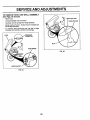
TO ADJUSTATTACHMENT
CLUTCH (See Fig.
ROTOR
24)
The electric clutch should provide years of service. The
clutch has a built-in brake that stops the pulley within 5
seconds. Eventually, the internal brake will wear so the
mower blades willnot stop as recommended. Adjustments
shouldbe made by an authonzed service technic'an.
•
Make sure attachment clutchand ignitionswitchesare
in the "OFF" position.
•
.012
Adjust the three nylon lock nuts until the space between clutchplate and rotor, measures .012 inches at
all three slot locations cut in side of brake plate.
NOTE: After installinga new electric clutch, runtractor at
full throttle, and engage and disengage electric clutch 10
cycles to wear in clutch plate.
TO REPLACE
(See Fig. 25)
MOWER
FIG. 24
BLADE DRIVE BELT
ELECTRIC
CLUTCH PULLEY
BELT REMOVAL •
Place attachment clutch in "DISENGAGED" position.
•
,
•
BRAKE PLATE
NYLON LOCK NUT (3)
The mower blade drive belt may be replaced withouttools.
Park the tractor on level surface. Engage parking brake.
Forassistance, there is a belt installation guide decal onthe
mower housing.
*
•
CLUTCH PLATE
GUIDE
IDLER BELT
IDLER
ILLEY
_
LH.
Turn height adjustment knob to lowest setting.
Move attachment lift lever forward to lower mower to its
lowest position.
Roll belt off electric clutch pulley.
Pull belt off both mandrel pulleys.
Spring belt guide away from idler pulley and pull belt off
idler pulley.
BELT INSTALLATION •
Place belt around back side and in groove of both
mandrel pulleys.
•
Spring' idler belt guide down and place belt around
rear side of idler puliey.
•
Roll belt over electric clutch pulley.
•
Make sure belt isin all pulley grooves and inside all belt
guides.
MOWER BLADE
DRIVE BELT
/
FIG. 25
21
SERVICE AND ADJUSTMENTS
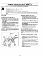
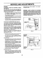
TO ADJUST
TO REPLACE
MOTION
Figs. 27 and 28)
BRAKE (See Fig. 26)
Your unit is equipped with an adjustable brake system
which is mounted on the right side of the transaxle.
Depressclutchibrake pedal and engage parking brake.
Measure distance between brake operating arm and
nut "A" on brake rod.
•
If distance is other than 1-1/2", disengage parking
brake, loosen jam nut and turn nut "A" until distance
becomes 1-1/2". Retighten jam nut against nut "A".
•
•
Engage parking brake and recheck distance.
Road test unit for proper stopping distance as stated
above. Readjust if necessary. If stopping distance is
still greater than six (6) feet in highest gear, further
maintenance is necessary. Contact your nearest Sears
Service Center.
BELT
•
Remove mower (See "TO REMOVE MOWER" in this
section of this manual).
•
•
•
Remove belt from stationary id[erand clutchingidler.
Remove clutch locator
Disconnect clutchwire harness.
•
Rotate clutch assemb!_ enou.gh to allow belt to be
removed downwards o'ff engine pulley, under belt
keeper, and around clutch assembly.
•
Remove belt carefully upwards from transmission input pulley and over cooling fan blades.
•
Install new belt by reversing above procedure.
IMPORTANT: REPLACE ONLY WITH BELT LISTED IN
THIS MANUAL.
WITH PARKING BRAKE "ENGAGED •
NUT •A"
ELECTRIC
CLUTCH
PULLEY
JAM NUT
,_
CLUTCH
CLUTCHING-IDLER
OPERATING
ARM
STATIONARY f
IDLER
FIG. 26
INPUT
PULLEY
_
DRAWBAR
BELT KEEPER
(See
Park the tractor on level surface. Engage parking brake.
For ease of service,remove rear drawbar from chassis and
belt keeperfromtransmission input pulley. For assistance,
there is a belt installation guide decal on bottom side of left
footrest.
If unit requires more than six (6) feet stoppingdistance at
high speed in highest gear, then brake mustbe adjusted.
•
•
DRIVE
0
FAN
MOTION
DRIVE BELT
FIG. 28
INPUT
PULLEY
FIG. 27
22
SERVICE AND ADJUSTMENTS
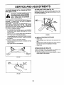
TO ADJUST
Fig. 29)
MOTION CONTROL
TO ADJUST STEERING
LEVER (See
If steering wheel crossbars are not horizontal (left to right)
when wheels are positioned straight forward, remove
steering wheel and reassemble per instructions in the
Assembly section of this manual.
"NEUTRAL" position of the motion controllever has been
preset at the factory and adjustment should not be necessary.
If your unit tends to "creep" when the motion controllever
is in "NEUTRAL" position, adjustthe neutral lever position
as follows:
FORWARD ADJUSTMENT•
Drive unit forward on a level surface.
•
Move motion control lever to the left and back until it
stops against forward adjustment plate and release
lever.
•
If unit "creeps" forward or backward, turn engine off
and set parking brake.
From underside of fender, loosen the two (2) bolts
securing forward adjustment plate and move plate 1/
16" opposite the direction the unit "creeps":
Forward "creep", move plate backwards 1/16 inch.
•
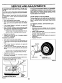
FRONT WHEEL TOE-IN/CAMBER
The front wheel toe-in and camber are not adjustable on
your unit. If damage has occured to affect the front wheel
toe-in or camber, contact your nearest Sears Service
Center.
TO REMOVE
WHEEL FOR REPAIRS
(See
Fig. 30)
* Block up axle securely.
o Remove wheel cover, retaining ring and washers to
allowwheel removal (rear wheel conta;ns a square key
- Do not lose).
•
Repair tire and reassemble.
Reverse "creep", move plate forward 1/16 inch.
•
•
•
Retighten bolts securely.
Repeat forward drive test and, if necessary, readjust
until "creep" is eliminated.
REVERSE ADJUSTMENT•
Drive unit in reverse on a level surface.
•
Move motion control lever tothe right and forward until
it stops against reverse adjustment plate and release
lever.
•
If unit "creeps" forward or backward, turn engine off
and set parking brake.
•
Loosen and move reverse adjustment plate in the
same manner as forward adjustment plate described
above:
WHEEL ALIGNMENT
•
.
On rear wheels only: align grooves in rear wheel hub
and axle. Insert square key.
Replace washers and snap retaining ring securely in
axle groove.
Replace wheel cover.
WASHERS
RETAINING
RING
Forward "creep", move plate backwards 1/16 inch.
Reverse "creep", move plate forward 1/16 inch.
•
Retighten bolts securely.
•
Repeat reverse drive test and, if necessary, readjust
until "creep" is eliminated.
J
If "creep" cannot be eliminated by the above adjustments,
contact your nearest Sears Service Center.
FORWARD ADJUSTMENT
REVERSE ADJUSTMENT
FIG. 30
BOLTS
PLATE
SQUARE KEY
(REAR WHEEL ONLY)
PLATE
_.,
FIG, 29
WHEEL COVER
MOTION
CONTROL
LEVER
23
SERVICE AND ADJUSTMENTS
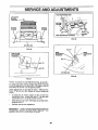
TO REPLACE FUSE (See Fig. 33)
TO START ENGINE WITH A WEAK BATTERY
(See Figs. 31 & 32)
Replace with 30 amp automotive-type plug-in fuse. The
fuse holder is located in the engine compartment, directly
in front of the heat shield.
CAUTION: Lead-acid batteries generate explosive gases. Keep sparks, flame
and smoking materials away from batteries. Always wear eye protection
When around batteries.
If your battery is too weak to start the engine, it should be
recharged. If "jumper cables" are used for emergency
starting, follow this procedure:
IMPORTANT; YOUR UNIT tS EQUIPPED WiTH A 12
VOLT NEGATIVE GROUNDED SYSTEM. THE OTHER
VEHICLE MUST ALSO BE A 12 VOLT NEGATIVE
GROUNDED SYSTEM. DO NOT USE YOUR TRACTOR
BATTERY TO START OTHER VEHICLES.
TO ATTACH JUMPER CABLES ° Connect each end of the RED cable to the POSITIVE
(+) terminal of each battery, taking care not to short
against chassis.
•
Connect one end of the BLACK cable to the NEGATIVE (-) terminal of fully charged battery.
FIG. 33
,
Con nect the other end of the BLACK cable to a panel
bolt on the Ieft side of the chassis, away from fueftank
and battery.
TO REMOVE CABLES, REVERSE ORDER •
BLACK cable first from left side of chassis and fully
charged battery.
° RED cable last from both batteries.
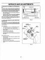
TO REPLACE HEADLIGHT
BULB
•
•
Raise hood.
Pull bulb holder out of the hole in the backside of the
grill,
•
Replace bulb in holder and push butb holder securely
back into the hole in the backside of the grill.
Close hood.
•
INTERLOCKS
AND RELAYS
Loose or damaged wiring may cause your tractor to run
poorly, stop runnmg, or prevent it from starting.
•
"POSITIVE ....
NEGATIVE"
(*)
(-)
FIG. 31
FIG. 32
24
Check wiring. See electrical wiring diagram in Repair
Parts section of this manual.
SERVICE AND ADJUSTMENTS
TO REMOVE HOOD AND GRILL ASSEMBLY
(See Figs, 34 and 35)
•
Raise hood.
•
Unsnap headlight wire connector.
•
•
Carefully remove springs from hinge brackets.
Stand at side of tractor. Grasp hood, tilt forward and
lift off hinge brackets.
•
To reinstall, slide hood pivot rod into slot in hinge
brackets, and carefully reinstall hood springs.
HOOD PIVOT ROD
HOOD
HINGE BRACKET
.HEADLIGHT
CONNECTOR
HOOD SPRING
FIG. 35
HINGE BRACKET
FIG. 34
25
SERVICE AND ADJUSTMENTS
i1|
ENGINE
TO ADJUST THROTTLE
(See Fig. 36)
CONTROL
High speed stop is factory adjusted.
damage may result.
CABLE
The throttle control has been preset at the factory and
adjustment shouldnot be necessary. Check adjustment as
described below before loosening cable, if adjustment is
necessary, procede as follows:
•
•
•
•
IMPORTANT:
NEVER TAMPER WITH THE ENGINE
GOVERNOR,
WHICH IS FACTORY SET FOR PROPER
ENGINE SPEED. OVERSPEEDING THE ENGINE ABOVE
THE FACTORY
HIGH SPEED
SETTING
CAN BE
DANGEROUS.
IF YOU THINKTHE ENGINE-GOVERNED
HIGH SPEED NEEDS ADJ_JSTING, CONTACT YOUR
NEAREST SEARS SERVICE
CENTER, WHICH HAS
PROPER EQUIPMENTAND
EXPERIENCETO
MA]<E ANY
NECESSARY ADJUSTMENTS.
With engine not running, move throttle control lever
from "SLOW" to "CHOKE" position. Slowly move lever
from "CHOKE" to "FAST" position.
Check to see if hole in throttle lever and hole in speed
controlbracket are aligned.
If holes are not aligned, loosen cable clamp screw and
align the holes by inserting a pencil or a 1/4" drill bit
through both holes.
CABLE
CLAMP
Pull throttle cable up to remove slack and tighten cable
clamp screw. Remove alignment pencil or drill bit.
TO ADJUST
CARBURETOR
(See Fig. 37)
SPEED CONTROL
BRACKET --.-.---
The carburetor has been preset at the factory and adjustment should not be necessary. However, minor adjustmentmay be requiredto cornpensate for differences infuel,
temperature, altitude or load. If the carburetor does need
adjustment, proceed as follows:
In general, turning the adjusting needles in (clockwise)
decreases the supply of fuel to the engine giving a leaner
fuel/air mixture. Turning the adjusting needles out
(counterclockwise) increases the supply of fuel to the
engine giving a richer fuel/air mixture.
IMPORTANT: DAMAGE TO THE NEEDLES AND THE
SEATS IN CARBURETOR MAY RESULT IF NEEDLE IS
TURNED IN TOO TIGHT.
PRELIMINARY SETTING •
THROTFLE
LEVER
FIG. 36
Be sure you have a clean air filter and the throttre
control cable is adjusted properly (see above).
IDLE SPEED
•
With engine off turn idle fuel adjusting needle in
(clockwise) closing it finger tight and then turn out
(counterclockwise) 1 turn.
FINAL SETTING -
•
Start engine and allow to warm forfive minutes. Make
final adjustments with engine running and shift/motion
control lever in "NEUTRAL" position.
•
Idle soeed setting- With throttle control lever in "SLOW"
position, engine should idle at 1625 RPM. If engine
idles too slow or fast, turn idle speed adjusting screw in
or out until correct idle is attained.
Do not adjust -
ADJUSTING
•
Idle fuel needle setting - With throttle control lever in
"SLOW" position, turn idle fuel adjusting needle in
(clockwise) until engine begins to die and then turn out
(counterclockwise) until engine runs rough. Turn needle
to a point midway between those two positions.
•
Recheck idle speed. Readjust if necessary.
ACCELERATION TEST -
IDLE FUEL
ADJUSTING /
NEEDLE
FIG. 37
Move throttle control lever from "SLOW" to "FAST"
position. If engine hesitates or dies, turn idle fuel
adjusting needle out (counterclockwise) 1/8 turn. Repeat test and continue to adjust, if necessary, until
engine accelerates smoothly.
26
STORAGE
Immediately prepare your tractor for storage at the end of
the season or ifthe unit will not be used for 30 days or more.
ENGINE
FUEL SYSTEM
IMPORTANT: IT lS IMPORTANT TO PREVENT GUM
DEPOSITS FROM FORMING IN ESSENTIAL FUEL
SYSTEM PARTS SUCH AS CARBURETOR, FUEL FILTER,
FUEL HOSE, OR TANK DURING STORAGE. ALSO,
EXPERIENCE INDICATES THAT ALCOHOL BLENDED
FUELS (CALLED GASOHOL OR USING ETHANOL OR
METHANOL) CAN ATTRACT MOISTURE WHICH LEADS
TO SEPARATION AND FORMATION OF ACIDS DURING
STORAGE. ACIDIC GAS CAN DAMAGE THE FUEL
SYSTEM OF AN ENGINE WHILE IN STORAGE.
•
Drain the fuel tank.
CAUTION: Never store the tractor with
gasoline in the tank Inside a building
where fumes may reach an open flame
or spark, Allow the engine to cool
before storing in any enclosure.
TRACTOR
Remove mower from tractor for winter storage. When
mower is to be stored for a period of time, clean it thoroughly, remove all dirt, grease, leaves, etc. Give blades
and underside of housing a good coat of grease or rust
preventative. Store in a clean, dry area.
•
Clean entire tractor (See "CLEANING" in the Maintenance section of this manual).
•
•
•
Start the engine and let it run until the fuel lines and
carburetor are empty.
•
Never use engine or carburetor cleaner products in the
fuel tank or permanent damage may occur.
Use fresh fuel next season.
•
NOTE: Fuel stabilizer is an acceptable alternative in
minimizing the formation of fuel gum deposits during storage. Add stabilizer to gasoline in fuel tank or storage
container. Always follow the mix ratio found on stabilizer
container. Run engine at least 10 minutes after adding
stabilizer to allow the stabilizer to reach the carburetor. Do
not drain the gas tank and carburetor if using fuel stabilizer.
Inspect and replace belts, if necessary (See belt replacement instructions in the Service and Adjustments
section of this manual).
Lubricate as shown in the Maintenance section of this
manual.
Be sure that all nuts, bolts and screws are securely
fastened. Inspect moving partsfordamage, breakage
and wear. Replace if necessary.
ENGINE OIL
Drain oit (with engine warm) and replace with clean engine
oil. (See "ENGINE" in the Maintenance section of this
manual).
Touch up all rusted or chipped paint surfaces; sand
lightly before painting.
BATTERY
CYLINDERS
•
Fully charge the battery for storage.
•
Remove spark plug(s).
•
After a period of time in storage, battery may require
recharging.
•
Pour one ounce of oil through spark plug hole(s) into
cylinder.
•
To help prevent corrosion and power leakage during
long periods of storage, battery cables should be
disconnected and batterycleaned thoroughly (see "TO
CLEAN BATTERY AND TERMINALS" in the Maintenance section of this manual).
•
Turn ignitionkeyto"START"
to distribute oil.
•
Replace with new spark plug(s).
After cleaning, leave cables disconnected and place
cables where they cannot come in contact with battery
terminals.
OTHER
•
Do not store gasoline from one season to another.
Be sure battery drain tube is securely attached to drain
in battery tray.
•
Replace your gasoline can if your can starts to rust.
Rust and/or dirt in your gasoline will cause problems.
°
If possible, store your unit indoors and cover it to give
protection from dust and dirt.
•
•
•
positionfor afewseconds
Cover your unit with a suitable protective cover that
does not retain moisture. Do not use plastic. Plastic
cannot breath which allows condensation to form and
will cause your unit to rust.
IMPORTANT: NEVER COVER TRACTOR
WHILE
ENGINE AND EXHAUST AREAS ARE STILL WARM.
27
TROUBLESHOOTING
PROBLEM
POINTS
CAUSE
CORRECTION
1.
2.
3.
4.
5,
6.
7,
Out of fuel.
Engine not =CHOKED" properly.
Engine flooded.
Bad spark plug,
Dirty air filter.
Dirty fuel filter.
Water in fuel.
1.
Fill fuel tank,
2.
3.
4.
5.
6.
7.
8,
9,
10,
Loose or damaged wiring.
Carburetor out of adjustment.
Engine valves out of adjustment.
8,
9.
t0.
See TO START ENGINE in operation section.
Wait several minutes before attempting to start.
Replace spark plug.
Clean/replace air filter.
Replace fue! filter.
Drain fuel tank and carburetor, refill tank with fresh
gasoline and replace fuel filter.
Check all wiring.
Contact Sears Service Department.
Contact Sears ServZce Department.
1.
2.
3.
4.
5.
6.
7.
8,
D_rtyair filter.
Bad spark plug.
Weak or dead battery.
Dirty fuel filter.
Stale or dirty fuel.
Loose or damaged wiring.
Carburetor out of adjustment.
Engine valves out of adjustment.
1.
2.
3.
4.
5.
6.
7.
8.
i
Will not start
Hard to start
Engine will not turn over
1.
2.
3,
4.
5.
6.
7.
8.
9.
10,
Englne clicks but will not
start
1.
2.
3.
4.
Weak or deadbattery,
Corrodedbatteryterminals.
Looseor damagedwiring.
Faultysolenoidor starter.
1. Rechargeor replacebattery.
2. Cleanbatteryterminals.
3. Checkall wiring.
4. Check!replacesolenoidor starter.
Loss of power
1.
2.
3.
4.
5.
6.
7.
8.
9.
Cutting too much grass/too fast.
Throttle in "CHOKE" position.
Build-up of grass, leaves and trash under mower.
Dirty air filter.
Low oil level/dirty oil.
Faulty spark plug.
Dirty fuel filter.
Stale or dirty fuel.
Water in fuel.
1. Setin "Higher Cut"position/reducespeed.
2. Adjust throttlecontrol.
3. Cleanundersideof mowerhousing.
10.
11.
12.
13.
14.
15.
Clutch/brake pedal not depressed.
Attachment clutch is engaged.
Spark plug wire is disconnected.
Weak or dead battery.
Blown fuse.
Corroded battery terminals.
Loose or damaged wiring.
Faulty ignition switch.
Fau_ solenoid or starter,
Faulty operator presence switch(es).
1.
2.
3.
4.
5.
6.
7.
B.
9.
10.
Clean[replaceair filter.
Replacesparkplug.
Rechargeor replacebattery,
Replacefuelfilter.
Drainfueltank andrefillwithfreshgasoline.
Checkall wiring.
ContactSearsServiceDepartment.
ContactSearsServiceDepartment.
Sparkplug wireloose,
Dirtyengine air screen/fins.
Dirty[clogged
muffler,
Looseordamagedwiring.
Carburetoroutof adjustment.
Engine valvesoutof adjustment,
4.
5.
6.
7.
8.
9.
10.
11.
12.
13,
14,
15.
i
Excessive vibration
Depress Clutch/brake pedal.
Disengage attachment clutch.
Connect wire to spark plug.
Recharge or replace battery.
Repiace fuse.
Clean battery terminals.
Check all wiring.
Check/replace ignition switch.
Check/replace solenoid or starter.
Contact Sears ServTce Department.
Cleanlreplace air filter.
Check oil level/change oil.
Clean and regap or change spark plug.
Replace fuel filter,
Drain fuel tank and refill with fresh gasoline.
Drain fuel tank and carburetor, refiUtank with fresh
gasoline and replace fuel filter.
Connect and tighten spark plug wire.
Clean engine air screen/fins.
Clean[replace muffler.
Check all wiring,
Contact Sears Service Department.
Contact Sears Service Department.
i |m
1,
2.
Worn, bent or loose blade.
Bent blade mandrel.
3.
Loose[damaged part(s).
1.
2.
3.
28
f
r i=l
:
Replace blade. Tighten blade bolt.
Replace blade mandrel,
Tighten loose part(s). Replace damaged parts.
i
i
|
i
TROUBLESHOOTING
CORRECTION
PROBLEM
CAUSE
Engine continues to run
when operator leaves seat
with attachment clutch
engaged
t.
_ul_
Poor cut-uneven
1.
2.
Worn, bent or _oose blade.
Mower deck notlevel.
3.
4.
Build-up of grass, leaves, and trash under mower.
Bent blade mandrel.
1.
Obstruction in clutch mechanism.
2.
3.
4.
5.
Mower drive belt out of adjustment.
Worn/damaged mower drive belt.
Frozen idter pulley.
Frozen blade mandrel.
Mower blades will not
rotate
Poor grass discharge
Headllght(s)notworking
Ofso equipped)
1.
2.
3.
4.
5.
6.
7.
8.
9.
10.
1.
2,
3,
4.
5,
POINTS
operato_safe_ presence _ntml system.
1.
1. Replaceblade. "lqghten
bladebolt.
2. Levelmowerdeck.
3. Cleanundersideofmowerhousing.
Engine speed too slow.
Travel speed too fast.
Wet grass.
Mower deck not level,
Low!uneven tire air pressure.
Wom, bent or loose blade.
Build-up of grass, leaves and trash under mower.
Mower drive belt worn or out of adjustment.
Blades improperly installed.
Improper blades used.
i=
4.
Replace blade mandrel.
1.
2.
3.
4.
5.
Remove obstruction.
Adjust mower drive belt.
Replace mower drive belt.
Replace idler pulley.
Replace blade mandrel.
1.
2.
3.
4.
5.
6.
7.
8.
9.
10.
Switch is "OFF".
Bulb(s) burned out.
Faulty iight switch.
Loose or damaged wiring.
Blown fuse.
i=
Check wiring, switches and connections, If not
corrected, contact Sears Service Department.
Place throttle control in =FAST" position.
Shift to slower speed.
A_lowgrass to dry before mowing.
Level mower deck.
Check tires for proper air pressure.
Replace/sharpen blade. "f3ghtanblade boil
Clean underside of mower housing.
Replace/adjust mower drive belt.
Reinstail blades sharp edge down.
Replace with blades listed in this manual.
1.
Turn switch "ON".
2.
3.
4.
5.
Replace bulb(s).
ChecK/replace light switch.
Check wiring and connections.
Replace fuse.
r
.H.
i
Battery will not charge
1.
2.
3.
4.
Bad battery cell(s).
Poor cable connections.
Faulty regulator (if so equipped).
FauLtyalternator.
1.
2.
3.
4.
Replace battery.
Checldclean all connections.
Replace regulator.
Replace attemator.
Tractor "creeps" with
motion control lever In
"neutral" position
1.
Motion control lever is out of adjustment.
1.
Adjust motion control lever.
29
SERVICE NOTES
30
12.5 HP 38" RIDING
SCHEMATIC
r
LAWN TRACTOR
- - MODEL
NUMBER
917.255551
RED
BATTERY
1
P_P
RED
i
FUSE 30 AMP.
AMMETER
WHITE
I
=
)
RED
I
STARTER
J
1
IC
D
1
WHITE
SOLENOID
i
WHITE
:
TI LLE R
ATTACHMENT
CONNECTOR
IGNITION
SWITCH
I
•
RED
I _
=
'
_
]
i
I
:---r
(_) DEPRESS
FOOT PEDAL
I__-SEAlSWITCH
(_) DISENGAGE
Aq-FACH MENT
_[
%;,
I
I I
oP&_,'-o_,
I.
...
:
(PEDAL UP)
_
_i
_
I
PRESENCE
RELAY #1
BLACK
.Eo
BLACK
I
,.
IGNITION
UNiT
"'1
BLACK
I
J
(NOT OCCUPIED)
EL.E,C%C
_l .._C'L,,_,,_.-._P_
....... " .... "
I
RELAY #2
INDICATOR LIGHTS
__
I
OPE-RATO_RESE-NCE
'
I CLUTCH/BRAKE
_! ,8%
....
I
I
I ......
(DISENGAGED}
I ; 8s -- %;:
o4-----
I
f"_l
PTO
,-=F,
..... E
'
I t
.....
_
RED
I
_
I
O
®
"J
{
'
,
SPARK
PLUG
"
i
HECK
OIL
LOW
FUEL
W
ALTERNATORI
YELLOW
REGULATOR
15 AMP
BLUE
2ovAo
(M,N)
_co,_,!
@ 3600 RPM.
AFTER FIRE
SOLENOID
A
w
NON-REMOVABLE
CONNECTIONS
REMOVABLE
CONNECTIONS
_)
I .....
I
l
IO...,XO
I .....
II
J
BROWN
••
RED
HEADLIGHT
SWITCH
[ .....
I
RED
I .....
HEAD LIGHTS
J
LOW FUEL SENSOR
(TANK FULL)
c
IGNITION SWITCH
POSITION
CIRCUIT
,,t,
OFF
ON
START
M+G
B+L
B + S+ L
F
I
'1'
PSI LOW-PRESSURE
SWITCH
(ENGINE OFF)
B
I
A
WIRING INSULATED CLIPS
PTO SWITCH
POSITION
CIRCUIT
OFF
ON
B -_"E,"C
+ D
B +_.A._C + F
31
RELAY
NOTE: IFWIRING INSULATED
CLIPS WERE REMOVED FOR
SERVICING OF UNIT, THEY
SHOULD BE REPLACED TO
PROPERLY SECURE YOUR WIRING
&
REPAIR PARTS
12.5 HP 38" RIDING LAWN TRACTOR
- - MODEL NUMBER 917.255551
ELECTRICAL
1
1
3
4
|
I
38
4
37--
27
28
25
26
13
32
REPAIR
PARTS
12,5 HP 38" RIDING LAWN TRACTOR
- - MODEL NUMBER 917.255551
ELECTRICAL
KEY
NO.
1
2
3
4
5
6
7
8
9
10
II
13
14
15
16
17
18
19
20
21
22
23
24
25
26
27
PART
NO.
7662J
127441
108824X
109748X
1107t2X
126019X
4022J
109310X
123620X
124211X
102972X
102501X
235R
STD532575
7603J
105687X
I09596X
I25603X
STD522507
STD551025
STD551125
STD541025
121264X
I02476X
4207J
121305X
DESCRIPTION
KEY
NO.
Bulb, Light
Harness, Light Socket
Fuse, 30 Amp
Relay
Switch, Light
Switch, PTO
Nut, Hex
Molded Key
Cover, Key Switch
Ignition, Nut
Switch, Ignition
Wire, Loop
Clip, Insulator
* Bolt,Carriage 1/4-20 x 7-1/2
Tray, Battery
Tube, Battery Tray
Clamp, Hose
Battery
* Bolt, Hex 1/4-20 x 3/4
* Washer 9/32 x 5/8 x 16 Ga.
*Washer, Lock 1/4
*Nut, Hex 1/4-20
Caps, Battery
Guard, Terminal
Cable, Ground
Switch, Seat
PART
NO.
28
29
32
33
34
35
36
37
38
39
40
41
42
43
44
45
46
47
48
49
50
51
---
121422)(
7192J
123198X
4799J
126835X
110143X
109553X
5114,.1
2751 R
719J
109081X
126773X
STD551125
STD541225
STD522505
STD551225
STD541425
STD601005
74780408
73680400
74760512
73680500
128343
101539X
--
120960X
DESCRIPTION
Ammeter
Tie, Cable
Nut, Wing 1/4-20
Cable, Battery
Assembly, Light Package
Bulb, Dashboard Light
Switch, Interlock, Clutch Pedal
Cable, Starter
Clip, Fuel Line
Cover, Terminal
Solenoid
Harness, Ignition
*Washer, Lock 1/4
* Nut, Jam I/4-20
*Bolt, Hex 1/4-20 x 1/2 Gr. 5
* Washer, Lock Ext. Tooth 1/4
* Nut, Keps 1/4-20
*Screw, Hex, Tap 10-24 x 1/2
Bolt, 1/4-20 x 1/2
Nut, Crownlock 1/4-20
Bolt, Hex Hd. 5/16-18 x 3/4
Nut, Crownlock 5/16-18
Manual, Owner's
Sheet, Instruction, Tractor 15 °
Slope
Decal, Battery
*STANDARD HARDWARE--
PURCHASE LOCALLY
NOTE: Ait component dimensions given in U.S. inches
1 inch = 25.4 mm
A
B
® 43
C
44
D
E
47 48
_45
®49
48
33
_51
REPAIR PARTS
12.5 HP 38" RIDING LAWN TRACTOR
- - MODEL NUMBER
917.255551
CHASSIS
76_
J J
6O
3O
31
REPAIR PARTS
12.5 HP 38" RIDING LAWN TRACTOR
- - MODEL NUMBER 917.255551
CHASSIS
KEY
NO.
PART
NO.
1
2
126626X
17490612
3
17490616
4
5
6
7
8
9
10
126656X
105529X
STD541431
124181X
126599X459
STD523707
17030808
11
12
STD541437
17490608
13
14
O_ 15
16
17
18
19
21
22
23
24
25
26
109873X
STD512505
105465X459
105464X459
74760412
126597X
STD551125
19131312
124029X
126598X
19131210
124238X
110436X
DESCRIPTION
KEY
NO.
Seat
Screw, Hex, Washer Hd. Thrd.
Roll 3/8-16 x 3/4
Screw, Hex, Washer Hal.Thrd.
Roll 3/8-16 x 1
Bracket, Pivot, Seat
Bolt, Shoulder 5/16-t8
* Nut, Crownlock 5/16-18
Spring, Seat
Fender
* Bolt, Fin Hex 3/8-16 x 3/4
Screw, Spidedock Hex #8 x
1/2 AB
*Nut, Crownlock 3/8-16
Screw, Hex Washer Hd. Thrd.
Rol13/8-16x1/2
Bracket, Fender
* Bolt, Fin Hex 1/4-20 x 1/2
Footrest, L.H.
Footrest, R.H.
Bolt, Hex 1/4-20 x 3/4
Plate, Neutral, Adjust R.H.
* Washer, Lock, Hvy Helical
Spring
Washer 13/32x 13/16x 12 Ga.
Lens Assembly
Plate, Neutral, Adjust L.H.
Washer 13/32 x 3/4 x 10 Ga.
Cap, Spring
Grommet, Split
A
B
C
D
28
29
30
31
32
33
34
35
36
37
38
44
45
46
47
48
49
50
51
52
53
54
57
58
59
60
63
64
65
66
67
E
PART
NO.
DESCRIPTION
19091416
122933)(
126842X
123665X
124025X459
121248X
126850X
124479X
127167X
127866
124294)(
9151R
124428X
19111610
2751R
19131614
72050411
123976X
121251X
123740X
130481
121246X
123913X
123914X
124040X
126741X
STD533707
126600X
STD551025
73951000
STD511005
F
G
KEY
NO.
Washer 9/32x7i8x16Ga.
Rivet, Ratchet, Nylon
Shield, Hood, Heat
Deflector, Heat
Hood Assembly
Bushing, Snap
Nut, Self Retaining 1/4-20
Washer, Black, Nylon
Chassis Assembly
Drawbar
Pan, Seat
Grommet
Slide, Set Seat
Washer 11/32xlx10Ga.
Clip, Fuel Ltne
Washer 13/32xl x14Ga.
Bolt, Carriage 1/4-20 x 1-3/8
Nut, Hex Large Flange, Lock
Strip, Foam
Spring, Seat Compression
Spacer
Bracket, Switch Mount
Bracket, Pivot, R.H.
Bracket, Pivot, L.H.
Spring, Extension
Grill
* Bolt, Carriage 3/8-16 x 3/4
Console, Shift, Fender Hydro
* Washer 9/32 x 3/4 x 16 Ga.
Nut, Keps #10-32 UNF
* Screw, Slotted Pen Head
H
J
K
L
14
_24
@19
_11
@
19_48
68
69
70
71
72
73
74
75
76
77
78
79
PART
NO.
DESCRIPTION
m.
4171 R
126654X
126575X
7605J
110739)(
73680400
105466X
17190516
124427X
STD551237
73610600
126938)(
126778X
126763X
126779X
4900J
126780X
121215X
---
126776X
126777X
106974X
127520
108631X
131265
126779)(
B
m.
#10-32 x 1/2
Clip, Insulated
Control, Bypass
Arm, Bypass Control
Bolt, Shoulder 1/4-20 UNC
Washer, Spring
Nut, Crownlock 1/4-20 UNC
Pad, Footrest
Screw, Hex 5/16-18 x 1
Spacer
*Washer, Lock Ext. Tooth 3/8
Nut, Fin Hex 3/8-24 UNF
Bumper, Hood
Decal, 12.5 HP OHV (Hood Side)
Decal, Rear Fender
Decal, Grill, Front
Deca!, Clutch/Brake
Decal, Chassis Side, 38"
Decal, Belt Installation (Under
Footrest)
Decal, Stripe, (Hood L.H.)
Decal, Stripe, (Hood R.H.)
Decal, Caution (Front Fender)
Decal, USA (Rear Fender)
Decal II
Decal, Light box
Decal, Grill
*STANDARD HARDWARE-PURCHASE LOCALLY
NOTE: Atl component dimensions given in U.S.
inches.
1 inch = 25.4 mm
M
N
_49_12_
P
O
9_6
_21
R
_72
_66
_73
REPAIR PARTS
12.5 HP 38" RIDING LAWN TRACTOR
- - MODEL NUMBER 917.255551
DRIVE
3
I
49
61
47
40
10
G
E
0
53
gl
17
/
D
71
51
74
71
45
44
36
72
75
52
REPAIR PARTS
12.5 HP 38" RIDING
LAWN
TRACTOR
- - MODEL
NUMBER
917.255551
DRIVE
KEY
NO.
1
2
3
4
5
6
7
8
9
10
11
13
14
15
16
17
18
19
20
21
22
23
24
25
26
27
28
29
30
31
32
33
34
35
36
37
38
39
40
41
42
43
44
45
46
47
48
PART
NO.
DESCRIPTION
KEY
NO.
13200300
13280336
126784X
Elbow, 90 ° 3/8-18 NPT
Nipple, Pipe
Engine 12.5 HP Model No.
CV12.5S Type No. 1438
M010208025 Screw MSx 1-1/4 × 25mm
121749X
Washer 25/32 x 1-1/4 x 16 Ga.
19131216
Washer 13/32 x 3/4 x 16 Ga.
124196X
Muffler
126577X
Keeper, Centerspan
126589X
Link, Pump Control
73040400
Nut 1/4-28 Nylcck
I26655X
Pin, Roll, Metric
1269t2X
Assembly, Friction Pack
126576X
V-Belt, Drive
121232X
Cap, Spindle
121187X
Bracket, Mounting, Hydro
126649X
Bracket, Transaxle
123583X
Key, Square 2.5x.1845/.1865
74760508
Bolt, Hex 5/16-18 x 1/2
121 t89X
U-Bolt 3/8-16 x 2-7/8
121199X
Spacer, Split
121748X
Washer 25/32x 1-5/8x 16 Ga.
106108X480
Rim, Rear
STD581075 * E-Ring
128342
Cover, Wheel
STD551131 *Washer, Lock, Hvy HeticalSpring
65139
Stem, Valve
59192
Cap, Valve
M010110100 Boit, Hex M10x1.5x100
t26197X
Washer 15/32 IDx 1-1/20D x 1/4
STD551143 *Washer, Lock 7/16
108218X
Clutch, Electric
109841X
Pulley, Engine
17030808
Screw, Spiderlock, Hex #8 x 1/2
19111212
Washer 11i32x3i4x12Ga.
123674X
Idler, Flat
4470J
Spacer
19131312
Washer 13/32 x 13/16x 12 Ga.
109070X
Keeper, Belt
121218X
Keeper, Belt, Engine L.H.
109169X
Locater, Clutch
110422X
Spring, Brake Return
74760516
Bolt, Hex 5/16-18× 1
106888X
Spring, Rod Brake
126634X
Rod, Brake
123533X
Cover, Pedal
120183X
Bearing, Nylon
122424X
Shaft, Foot PedalAssembly
B
C
4 _
D
53
E
PART
NO.
DESCRIPTION
49
50
51
52,
53
54
55
56
57
58
60
61
62
63
64
65
66
67
STD571810
7733J
125638X
105710X
STD541437
123205X
12000039
110812X
123789X
105709X
STD523715
127783
105706X
101326L
19211616
I26910X
17490612
17490616
68
69
71
72
73
STD523707
STD523710
STD561210
STD551037
STD541437
74
75
76
77
78
79
80
81
82
83
84
85
86
87
88
89
90
91
--
STD541237
4497H
105730X
126592X
126639X
126590X
126811X
126591X
STD581050
STD551231
STD523727
121851X
7152J
STD541431
STD533107
127073X
17490612
2751R
126779X
* Pin, Roll 3/16 x 1
Cap, Plunger
Rod, Brake, Park
Link, Clutch
* Nut, Lock 3/8-16
Retainer, Belt
Ring, Klip
Washer, Hardened
Arm, Idler
Spring, Return, Clutch
*Bolt, Hex 3/8-16 x 1-1/2
Pulley, Idler
Bearing
Deflector, Muffler
Washer 21/32 x 1 x 16 Ga.
Spring, Extension
Retainer, Spring
Screw, Hex, Washer Hd. Thrd. Roll
3t8-16 x I
* Bolt, Fin Hex 3/8-16 x 3/4 UNC
* Bolt, Hex 3/8-16 x 1
* Pin, Cotter 1/8 x 3/4
* Washer 13/32 x 13/16 x 16 Ga.
* Nut, Lock Hex W/Washer Insert
3/8-16
* Nut, Hex Jam 3/8-16
Clip, Hairpin
Keeper, Belt, Engine
Lever, Control Assembly
Grip, Knob
Bushing, Pivot L.H.
Tire, Rear
Washer, Shim
* E-Ring
*Washer, Lock External Tooth
* Bolt, Hex 3/8=16 x 2-3/4
Spark Arrester Kit
Tube (not furnished with tractor)
* Nut, Lock 5/16-I8
* Bolt, Carriage 5/16-18 x 3/4
Strip, Foam
Screw, Hex Wsh. Thdrl. 3/8-16 x 3/4
Clip, Insulated
Decal, Wheel Cover
*STANDARD HARDWARE - - PURCHASE LOCALLY
NOTE: All component dimensions given in U.S. inches
1 inch = 25.4 mm
G
J
43
28
@s3
37
L
N
O
P
Q
REPAIR
PARTS
12.5 HP 38" RIDING
STEERING
AND FRONT
LAWN
TRACTOR
- - MODEL
NUMBER
917.255551
AXLE
55
56
59
57
_58
6O
64
61
38
REPAIR
PARTS
12.5 HP 38" RIDING LAWN TRACTOR
- - MODEL NUMBER 917.255551
STEERING AND FRONT AXLE
KEY
NO.
1
2
3
4
5
6
7
8
9
10
11
13
I4
I5
16
17
18
19
21
22
24
25
26
27
28
29
30
31
32
34
35
36
39
PART
NO.
DESCRIPTION
KEY
NO.
126532X
Dash
74180512
Screw, Truss Head 5/16-18 x 3/4
STD541431 *Nut, Keps 5/16-18
109816X
Nyliner, Snap In
126235X
Control, Throttle
108171X
Support, Battery
126684)(
Washer 5i8x1/4x16Ga.
124417X
Boot, Steering Shaft
126709X
Saddle
17490608
Screw, Hex Washer Hd. Thrd. Roll
3/8-16x 1/2
2751 R
Clip, Insulated
126805X
Insert, Steering Wheel
STD541350 * Nut, Lock, Hex, Jam 1/2-20
100712K
Washer 2-1/4
121472X
Wheel, Steering
100711L
Adapter, Steering Wheel
STD551125 *Washer, Lock 1/4
71070410
Screw, Socket Hex 1/4-20 x 5/8
71141008
Screw #10-24x 1/2
STD611005 *Screw, HexTapping #10-16x 1/2
124373X
Bushing, Steering
124036X
Bracket, Steering
17490612
Screw, Hex Washer Hd. Thrd. Ro31
3/8-16 x 3/4 Type TT
6266H
Bearing, Thrust
124034X
Gear, Sector
124035X
Shaft, Support
12000029
Ring, Klip
57079
Washer, Hardened
128752
Shaft, Steering,
128341
Cover, Wheel
17490512
Screw, Hex Washer Hd. Thrd. Roll
5/16-18 x 3/4
124033X
Shaft, Pittman
74761060
Belt, Hex 5/8-1 lx 3-3/4
40
41
42
45
46
47
48
49
50
51
52
53
54
55
56
57
58
59
60
61
63
PART
NO.
DESCRIPTION
105669X
110438X
73601000
3366R
121334X
19111216
STD551t31
STD54!531
STD551137
73610600
128122
105656X
130524
278H
9040H
I06732X480
59192
65139
126810X
121749X
59904
Axle, Front
Spacer, Bearing, Front Axle
Locknut, Flange 5/18-16
Bearing
Rod, Tie
Washer 11/32 x3/4 x 16 Ga.
* Washer, Lock Hvy. Helical Spring
* Nut, Hex, Nylon 5/16-24 UNF
* Washer, Lock 3/8
Nut, Fin Hex 3/8-24 UNF
Link, Drag
Spindle, L.H.
Spindle, R.H.
Fitting, Grease
Bearing, Grease
Rim, 6" Front
Cap, Valve
Stem, Valve
Tire, Front
Washer 25/32 x 1-1/4 x 16 Ga.
Tube, Front (Not furnished with
tractor)
Washer 25/32 x 1-5/8 x 16 Ga.
64 121748X
66 126641X
Tool Box, Limited
Washer 27/32 x 1-t/4 x 16 Ga.
68 19272016
69 t21232X
Cap, Spindle
70 73731000
Nut, Keps #10-24 UNC
71 126471X
Clip, Insulated
72 19212010
Washer 21/32 x1-1/4 x 10 Ga.
-108456X
Decal, Instruction (Dash Panel)
Decal, Dash Panel
_
126775X
_
126779X
Decal, Wheel Cover
-126781X
Decal, Parking Brake (Dash Panel)
-126782X
Decal, Steering Wheel Cap
*STANDARD HARDWARE-PURCHASE LOCALLY
NOTE: All component dimensions given in U.S. inches
1 inch = 25.4 mm
A
B
D
39
E
F
REPAIR
PARTS
12.5 HP 38" RIDING LAWN TRACTOR
- - MODEL NUMBER 917.255551
LIFT ADJUSTMENT
42
4O
REPAIR PARTS
12.5 HP 38" RIDING LAWN TRACTOR
- - MODEL NUMBER 917,255551
LIFT ADJUSTMENT
KEY
NO.
1
2
3
5
6
7
8
9
10
11
12
13
14
15
16
17
18
19
20
21
22
23
24
25
26
27
28
29
30
31
32
33
PART
NO.
DESCRIPTION
KEY
NO.
126971X
126652X
STD541237
19131016
110807X
STD601005
2876H
123549X
126798)(
101335K
124028X
123487>(
17490608
Rod, Lift, Adjustment
Knob, Height Adjust
* Nut, Hex, Jam 3/8-16
Washer 13!32x5i8x 16Ga.
Nut, Special
*Screw, Hex, Tapping, #10-24x 1/2
Spring
Cap, Fuel
Tank, Fuel
Line, Fuel
Grommet
Clamp, Hose
Screw, Hex Washer Thrd. Roll
3/8-16 x 3/4
19091416
Washer 9/32 x 7/8 x 16 Ga.
122795X
Panel, Dash L.H.
121794X
Cover, Access
126276X
Panel, Dash R.H.
19211416
Washer 21/32 x 7/8 x 16 Ga
STD581062 *E-Ring
124385X
Button, Plunger
122512X
Spring, Compression
17490412
Screw, Hex Washer Thrd. Roll
1/4-20 x 3/4
STD560907 *Pin, Cotter
110810X
Trunnion, Depth Stop
120183X
Bearing, Nylon
19151216
Washer 15i32x3/4x16Ga.
12000037
Ring, Ktip
123933X394 Pointer, Height Indicator
122516X
Shaft, Lift
120529X
Washer, Nylon .44 x .75 x 032.
122364X
Plunger
126640X
Grip, Handle
34
35
36
37
38
39
40
41
42
43
44
45
47
48
49
50
51
52
53
54
55
56
57
58
59
60
61
62
63
64
65
---
PART
NO.
DESCRIPTION
4939M
Retainer, Spring
110029X
Link, Lift
110447X
Trunnion, Lift
110448X
Link, Lift, Adjustable
121598X
Arm, Suspension R.H.
105848X
Bolt, Shoulder 3/8-16
121599X
Arm, Suspension L.H.
I06308X
Trunnion, Lift, Lower
STD541050 *Nut, Hex 1/2-13
9135R
Retainer, Spring
19171516
Washer 17/32 x 15/16 × 16 Ga.
4921H
Retainer, Spring
123935X
Plug, Hole
74780516
Bolt, Hex Fin 5/16-18UNC x 1
STD551131 *Washer, Lock Hvy Helical Spring
19112410
Washer 11/32x 1-1/2x 10 Ga.
123934X
Scale, Height Indicator
73710700
Nut, Crownlock 7/16-20
122514X
Rod, Assembly, Lever
105767X
Pin, Groove
STD541343 *Nut, HexJam 7/16-20
STD533707 * Screw 3/8-16 x 3/4
108236X
Bracket, Switch
73980600
Nut, Flangelock 3/8-16
110739X
Washer, Spring
123650)(
Stud, 1/4 Turn
105736X
Shield, Heat
STD551025 *Washer 9i32x5i8x16Ga.
105838X
Retainer, I/4 Turn
105839X
Receptacle, 1/4 Turn
127073X
Strip, Foam
127074X
Decal, Lift Lever
*STANDARD HARDWARE - - PURCHASE LOCALLY
NOTE: All component dimensions given in U.S. inches
1 inch = 25.4 mm
41
REPAIR PARTS
12.5 HP 38" RIDING LAWN TRACTOR
- - MODEL NUMBER 917.255551
38" MOWER
I
!
49
!
I
"E"
42
42
REPAIR
PARTS
12,5 HP 38" RIDING LAWN TRACTOR
- - MODEL NUMBER 917.255551
38" MOWER
KEY
NO.
1
2
3
4
5
6
7
8
9
10
11
13
14
15
16
18
20
21
22
23
25
26
29
30
31
32
33
34
PART
NO.
106085X
121458X
8417J
STD541437
19111216
STD533106
105896X
110452X
106734X
106735X
106736X
105304X
129762X
105744X
4921H
109835X
STD541431
109598X
109597X
STD533107
109503X
109504X
STD523722
127162X
106902X
123688X
106513X
110445X
DESCRIPTION
KEY
NO.
V-Belt
Housing
Runner, R.H.
*Nut, Lock 3/8-16
Washer 11i32x3i4x16Ga.
* Bolt, Carriage 5/16-18 x 5/8
Bracket, Deflector
Pushnut
Spring, Deflector
Rod, Hinge
Deflector, Shield
Cap, Sleeve
Link, Parallel
Pin, Hinge, Front
Spring, Retainer
Pin, Hinge, Rear
*Nut, Lock 5/16-I8
Bracket, Lift R.H.
Bracket, Lift L. H.
*Bolt, Carriage 5/16-18 x3/4
Support, Arm
Stop, Deck, Front
*Bolt 3/8-16x2-1/4
Arm, Idler
Spacer
Pulley, Idler
Washer, Wear 1/I6"
Plate, Support Mandrel L.H.
A
@20
B
PART
NO.
35
36
37
121687X
100668L
17490620
38
39
40
41
42
43
44
46
47
48
49
50
51
-----
19131210
121263X
19132012
STD551137
STD623715
102727X
STD55!037
STD533712
7631J
19111016
108673X
STD533707
105857X
108682X
3713J
121343X
122217X
*STANDARD
NOTE:
C
E
Q2o@4
43
DESCRIPTION
Mandrel Assembly
Plate, Support Mandrel
Screw, Hex Washer Hd. Thrd. Roll
3/8-16 x 1-1/4
Washer 13/32 x 3/4 x 10 Ga.
Blade
Washer 13/32 x 1-1/4 x 12 Ga.
Washer, Lock 3/8
Bolt, Hex 3/8-24 x 1-1/2 Gr. 5
Spring, Extension
Washer 13/32 x 13/16 x 16 Ga.
Bolt, Carriage 3/8-16 x 1-1/4
Runner, L.H.
Washer 11/32 x 5/8 x 16 Ga.
Bracket, Susp., Rear, L.H.
Bolt, Carriage 3/8-16 x 3/4
Bracket, Susp., Rear, R.H.
Decal, Belt Installation
Decal, Instruction, Caution
Decal, Cut Finger
Replacement Deck Assembly
(Complete)
HARDWARE
- - PURCHASE
All component dimensions
1 inch = 25.4 mm
H
N
LOCALLY
given in U.S. inches
REPAIR PARTS
12.5 HP 38" RIDING LAWN TRACTOR
- - MODEL NUMBER 917.255551
TRANSAXLE AND PUMP ASSEMBLY
13
3
12
9
.15
))
I2
\
\
3
11
10
KEY
NO.
1
2
3
4
5
6
7
8
9
10
11
12
13
14
15
16
17
PART
NO.
19092016
STD551125
STD55113I
121188X
STD522507
126578X
126579X
I2121IX
126581X
---
STD523145
121323X
STD541431
7368o4o0
STD5237O7
STD541437
DESCRIPTION
Washer 9/32x I-1/4 x 16 Gauge
* Washer, Lock, Heavy Helical Spring
* Washer, Lock
Bracket, Pnt. Mounting, Differential
* Bolt, Hex 1/4 - 20 UNC x 3/4
Fan, Hydro, 7"
Pulley, Transaxle
Standoff, Fan, Hydro
Guard Assembly, Belt
Differential Assembly (See pages 46 & 47)
Pump Assembly (See page 45)
*Bolt, Hex, Fin 5/16 - 18 UNC x 4.5
Reservoir Pump
* Nut, Crownlock 5/16 - 18
Nut, Crownlock 1/4 - 20 UNC
* Bolt 3/8 - 16 x 3/4
* Nut 3/8 - 16 UNC
*STANDARD HARDWARE- - PURCHASE LOCALLY
NOTE: All component dimensions given in U.S. inches. 1 inch = 25.4 mm
44
A
@17
REPAIR
PARTS
12.5 HP 38" RIDING LAWN TRACTOR
SUNDSTRAND
PUMP ASSEMBLY
- - MODEL NUMBER 917.255551
MODEL NUMBER
BDU-10S
6
5
I
2
12
52
42
37
30,
21\
42
OVERHAUL
SEAL KIT
_,59
COMPLETE
"L/60
PUMP
KEY
NO.
1
2
3
4
5
6
8
11
12
13
14
15
17
18
19
20
21
22
25
30
3I
PART
NO.
122756X
122716X
122745X
122715X
122700X
122699X
122767X
122747X
122717X
! 22748X
122749X
127146X
122770X
122771x
127147X
122773X
122722X
122750X
127148X
122723X
127149X
DESCRIPTION
KEY
NO.
Shaft, Pump
* Ring, Retaining
Bearing, Ball
* Spacer
* Seal, Lip
* Ring, Retaining
Bearing, Cradle
Bearing, Journal
* Seal, Lip
Arm, Trunnion
Guide, Slot
Housing Kit, Transmission
Bearing, Thrust Ball
Plug, Pipe
Center Section Kit
Bearing, Needle
* Seal, Lip
Shaft, Motor
Swashplate, Variable
* Seal, Lip
Block Kit, Cylinder (PUMP)
45
PART
NO.
32
36
37
38
39
40
41
42
46
47
50
51
52
55
58
59
60
I27150X
I27151X
122786X
122718X
122731X
122730X
122728X
127152X
122787X
t22752X
122788X
122789X
122754X
127153X
122727X
122790X
127154X
61
121430X
ASSEM BLY r
DESCRIPTION
Block Kit, Cylinder (MOTOR)
Plug, Plastic
Pin, St. Hdls.
Gasket, Center Section
Filter
Washer, Thrust
Spring, Helical Compression
Check Valve Kit
Plug, St. Thd.
Screw Socket Head Cap
Washer, Thrust
Pin, Spiral
Plug, St, Thd.
Bypass Valve Kit
Adhesive Label, Bar Coded
Plug, St. Thd.
Overhau] Seal Kit, BDU-10
Includes; items marked with * and
O-Rings for Check Valves and
Bypass Valve
Complete Pump Assembly
REPAIR PARTS
12.5 HP 38" RIDING LAWN TRACTOR
- - MODEL NUMBER 917.255551
AGRI-FAB TRANSAXLE MODEL NUMBER 486.121431X
5R
22
5
16
\
62\
17
43
49
SELECTIVE
45
65
I
l SHELL DURINA-O
(2o oz.) GREASE I
52
REPAIR PARTS
12,5 HP 38" RIDING LAWN TRACTOR
- - MODEL NUMBER
917.255551
AGRI-FAB TRANSAXLE MODEL NUMBER 486.121431X
KEY
NO.
PART
NO.
1
2
3
4
5
6
7
8
9
10
11
12
13
14
15
16
17
18
19
20
21
22
23
24
25
26
27
28
-- -- 29
30
31
32
33
34
35
122614X
122615X
122616X
122620)(
122621X
122622X
122623)(
122624X
122625X
122626X
122688X
122629X
122631X
122633X
122634X
122640X
122641X
122642X
122643X
122644X
122645X
122646X
122647X
122648X
122649X
122650)(
122651X
123061X
122678X
122654X
122656X
122653X
122659X
122660X
122662X
122663X
122664)(
DESCRIPTION
Housing, Half L.H.
Housing, Half R.H.
Axle L.H.
Axle R.H.
Bearing, Ball
Washer, Flat 3/4 x 1-1/8 x .030
Gear, Miter
Gear, Miter
Nut, Hex Jam W/Patch 1/2-20
Shaft, Cross
Screw, Stud
Snap, Ring
Bearing, Thrust
Housing Assembly, Differentiat
Bearing, Flange
Gear, Differential 72 Tooth
Bolt, Torx Head 1/4-28 x 5/8"
Shaft, Input
Snap, Ring
Retaining Ring 7/16"
Housing, Input Bearing
Bearing, Needle
Bearing, Thrust
Washer, Flat 5/8 x 1-1/8 x .030
Key, Hi-Pro 3/32 x 5/8
Screw, Hex W]Patch 1/4-20 x 3/4
Gear, Input Pinion 17 Tooth
Washer, Flat .62 x 1 x .05
Washer, Flat .62 x 1.125 x .060
Washer, Flat .62 x 1 x .040
Pin, Cotter
Nut, Castle 5/16-24
Washer, Flat .343 x .88 x .062
Arm, Brake Actuator
Pin, Brake Actuating
Brake, Yoke
Disc, Brake
KEY
NO,
PART
NO.
36
37
38
39
40
41
42
43
44
45
46
47
48
49
--50
51
52
53
54
55
56
57
58
59
60
61
62
63
64
-- 65
66
- --
123065X
122666X
122667)(
122668X
123066X
122670)(
122671X
126982X
122673X
122674)(
122675X
123059X
123060X
122654X
123061X
122689)(
121839X
126975X
122682X
122683X
122684X
122685X
122686X
122687X
122652X
123062)(
123063X
126976X
126977X
126978X
126979X
126980X
126981X
121431X
DESCRIPTION
Key, Hi-Pro 3/16 x 5/8"
Screw, Hex 1/4-20 x 1.50
Plate, Puck
Puck, Brake
Screw, Hex W/Patch 1/4-20 x 2.00
Screw, Hex Self-Tap 1/4-20 x 2.00
Screw, Hex Self-Tap 1/4-20 x 3.00
Beadng, Ball
Bearing, Ball
Shaft, Pinion W/11 Tooth Gear
Shaft, Drive
Bearing, Needle
Bronze Thrust Brg. 5/8 x 1-1/4 x 7/64
Washer, Flat .62 x 1.0 x .040
Washer, Flat .62 x 1.0 x .050
Spacer
Coupling
Gear, 60 and 17 Tooth
Nut, Hex 1/4-20
Gear, Drive Pinion 17 Tooth
Bolt, Square Head
Washer 15/16 x .265 x .125
Washer 1/4" Spring Lock
Pin, Roll 3/16" x 1/2"
Washer, Flat .62 x 1.0 x .030
Pin, Dowel 3/32 x 1/4
Seal, Grease
Shell, Durina-O Grease (20oz.)
Washer, Head Spring Lock 1/4"
Washer, Flat .50 x 1.0 x .020
Washer, Flat .50 x 1.0 x .030
Assembly, Gear, Reduction
Assembly, Shaft, Input
Transaxle Assembly Complete
NOTE: All component dimensions given in U.S. inches
1 inch = 25.4 mm
REPAIR PARTS
12.5 HP 38" RIDING TRACTOR - - MODEL NUMBER 917.255551
ENGINE KOHLER - MODEL NUMBER CV12.5S, TYPE NUMBER 1438
AIR INTAKE/FILTRATION
1
2
3
4
5
6
7
8
9
10
12 341 01
12 096 06
12 100 01
X-25-63
12 083 08
12 083 05
12 072 03
12 086 01
12 041 02
12 094 01
Knob, air cleaner cover
Cover, air cleaner
Wing nut
Washer, plain 1/4
Precleaner, element
Element, air cleaner
Stud, mounting plate
Screw, mtg. plate stud
Gasket, air cleaner
Base, air cleaner
lO
ENGINE CONTROLS
1
2
3
4
5
12 079 03
12 237 01
SM-0645020
SM-0545016
12 536 01
6
7
8
9
I0
11
12
13
14
15
SM-0443025
12 089 11
12 089 04
12 089 12
S M-0641060
SM-0642025
12 090 05
25 158 09
12 079 01
25 158 08
Linkage, choke
Clamp, cable
Screw, hex. hd. M6 x 1.0x 20 (2)
Screw, cable clamp
Control, speed assembly (Includes
6-8)
Screw
Spring
Spring, choke return
Spring, governor
Nut, governor arm M6 x 1.0
Screw, governor armM6 x 1.Ox 25
Lever, governor
Bushing
Linkage, throttle
Bushing
/
11
48
3
REPAIR PARTS
12.5 HP 38" RIDING TRACTOR - - MODEL NUMBER 917.255551
ENGINE KOHLER - MODEL NUMBER CV12.5S, TYPE NUMBER 1438
._./2
BLOWER HOUSING & BAFFLES
1 SM-0545010
2 12 146 01
3 12 063 01
4 12 O96 01
5 12 027 04
6 12063 02
7 12 313 03
8 12 O63 03
Screw, mounting M5 x 0.8 x 10(14)
Plate, blower housing
Baffle, cylinderbarrel
Cover, starter
Housing, blower
Baffle, carburetor
Grommet, blower housing
Baffle, cylinderhead
CRANKCASE
1
2
3
4
5
6
7
8
9
10
11
12
13
14
15
16
17
18
19
20
21
22
23
Block, cylinder (Use Short block
part # 12 522 O2)
Seal, crankshaft
12 032 03
Bearing, crankshaft (Std.) (Flywheel
12 030 01
end)
Bearing, crankshaft (.25)
12 030 02
Bearing, crankshaft {.50)
12 030 03
Strap, lifting
12 445 02
SM-0839025 Screw, lifting strap
Dowel, locating (4)
12380 03
Camshaft assembly (Includes 7)
12 010 02
Spring, actuating
12 089 05
Shim, camshaft
12 422 01
Shim, camshaft (A.R.)
2 422 02
Shim, camshaft (A.R.)
12 422 03
Shim, camshaft (A.R.)
12 422 11
Shim, camshaft (A.R.)
12 422 12
Shim, camshaft (A.R.)
12 422 06
Shim, camshaft (A.R.)
12 422 07
Shaft, balance
12 144 04
Piston wiRing Set (Std.)
12 874 01
Piston w/Ring Set (.25)
12 874 02
Piston w/Ring Set (.50)
12 874 03
Retainer, piston pin (2)
1201802
Ring Set (Std.)
12 108 01
12 108 02
Ring Set (.25)
12 I08 03
Ring Set (.50)
Connecting Rod (Std.)
12 O67 01
Connecting Rod (.25)
12 067 02
Pin, governor regulating
12 380 01
Gear, governor assembly
12 O43 O5
SM-0631005 Washer, governor gear thrust
Shaft, governor gear
1214402
52 139 09
Ptug, cup
Shaft, governor cross
12 144 01
SM-0631015 Washer, governor shaft
Seal, governor cross shaft
1203201
Washer, plain
X-25-102
Pin, governor hitch
12380 O4
I/"
20
./
_\ _18
,3.
/
\
'
49
S
REPAIR PARTS
12.5 HP 38" RIDING TRACTOR - - MODEL NUMBER 917.255551
ENGINE KOHLER - MODEL NUMBER CV12.5S, TYPE NUMBER 1438
CRANKSHAFT
1
12 01402
Crankshaft
FU EL SYSTEM
1
2
3
4
5
6
7
8
9
10
11
12
13
14
15
16
12 853 01
12 313 05
12 041 01
12 265 01
12 313 01
12 041 01
12 041 02
M-0629122
48 154 01
SM-0641060
25 353 20
X-426-9
45 050 01
12 368 01
12 089 09
12 086 04
Kit, carburetor w/gaskets (Includes
6,7,14-29)
Grommet
Gasket, carburetor (2)
Deflector, heat
Grommet
Gasket, carburetor
Gasket, air filter
Stud, carburetor M6 x 1.0 x 110 (2)
Clp, fuel line
Nut, carburetor M6 × 1.0 (2)
Hose, fuel
Clamp, fuel line (2)
Filter, fuel
Needle, idle
Spring, idle speed
Screw, idle speed adj.
17
18
19
20
21
22
23
24
25
26
27
28
29
12 089
12 146
25 086
12 144
12 144
12 089
12 146
12 337
12 757
12 041
12 104
12 041
12 086
09
03
27
09
08
10
02
01
02
05
01
06
05
Spring, idle fuel
Plate, throttle
Screw, throttle plate (2)
Shaft, throttle w/lever & seal
Shaft, choke
Spring, choke return
Plate, choke
Jet, main
Kit, loaf
Gasket, bowl
Bowl, fuel
Gasket, bowl ret. screw
Screw, fuel bowl
NOT ILLUSTRATED
12 757 01
Kit, carburetor repair
12 755 09
Kit, high altitude jet
3
19_..
21
£__=
17-___
7
8
14
23
_26
_
5O
-----27
_28
_29
REPAIR PARTS
12.5 HP 38" RIDING TRACTOR - - MODEL NUMBER 917.255551
ENGINE KOHLER - MODEL NUMBER CV12.5S, TYPE NUMBER 1438
STARTING SYSTEM
1
2
3
4
5
6
7
8
9
10
SM-0839065
12 468 01
12 098 05
1275512
12 755 06
12 227 01
12 170 02
12 086 02
!2 243 01
48 755 15
Screw, bendix starter M8 x 1/25 x
65.5 (2)
Washer (2)
Starter assembly (Includes 4-10)
Kit, drive (Includes 5)
Kit, drive parts
Cap, drive end
Armature
Screw, hex. flange
Cap, commutator end (Includes 10)
Kit, brush
7
NOT ILLUSTRATED
52 357 01
Lubricant, starter
OIL PAN/LUBRICATION
1
2
3
4
5
6
7
8
9
12 038 01
12 153 02
1212304
SM-0545020
12 153 01
12 162 02
12 096 03
SM-0545016
SM-1039025
10
11
12
13
14
15
16
17
18
19
2O
21
22
12 126 02
12 O89 O3
12 462 01
12 208 01
52 050 02
12 136 01
X-75-23
52 099 06
X-75-10
I2 393 01
12 032 04
12 096 02
SM-0545016
23
24
25
12 032 03
SM-0839045
12 199 09
Dipstick
O-Ring, upper oil fill tube
Tube, oil fill
Screw, oil fill tube M5 x 0.8 x 20
O-Ring, lower oil fill tube
Screen, oil pick-up
Cover, oil pick-up screen
Screw, screen cover
Screw, oil pump relief valve bracket
M10 x 1.5 x 25
Bracket, oil pump relief bracket
Spring, oil pump reJief valve
Piston, oil pump relief valve
Body, oil pump relief valve
Filter, oil
Adapter
Plug
Switch, oil pressure
Plug, sq. hd. solid 3/8 N,P,T,F, (2)
Pump, oil
O-Ring, oil pump cover
Cover, oil pump
Screw, oil pump cover M5 x 0.8 x
16 (3)
Seat, oil (P.T.O. end)
Screw, oil pan M8 x 1.25 x 45 (12)
Pan, oil
C_----" 2
#_--9
4
14
=:_--
20
_21
51
REPAIR PARTS
12.5 HP 38" RIDING TRACTOR -- MODEL NUMBER 917.255551
ENGINE KOHLER - MODEL NUMBER 0V12.5S, TYPE NUMBER 1438
EXHAUST
M-0829036
2
3
4
5
6
12 041 03
SM-0841080
12 126 11
12 445 01
SM-0645025
Stud, exhaust manifold M8 x 1.25x
20 (2)
Gasket, exhaust manifold
Nut, muffler mtg M8 x 1.25 (2)
Bracket, muffler
Strap, lifting
Screw, lifting strap M6 x 1.0x 25 (3)
S
4
_1
6
Short Block 12 522 02
Gasket Set 12 755 01
IGNITION/ELECTRICAL
1
2
3
4
5
6
7
8
9
SM-1040045
52 468 15
12 162 01
SM-0639016
1211201
12 15701
X-42-15
41 403 09
SM-0639016
lO
11
12
13
236602
236473
12 025 01
SM-0544025
Screw, flywheel mounting
Washer, flywheel mtg. screw
Screen, grass
Screw, fan mounting (4)
Spacer, fan (4)
Fan
Key
Rectifier-regulator
Screw, rectifier-regulator M6 x 1.0 x
16 (2)
Connector, rectifier-regulator
Connector (3 contact)
Flywheel assembly
Screw, stator mounting M5 x 0.8 x
25 (4)
14
SM-0545010
15
16
17
12 154 02
41 085 07
12 132 02
X-728-1
SM-0545010
12 584 01
SM-0545020
18
19
20
21
Screw, stator harness clip M5 x 0.8
xl0
Clip, stator harness
Stator - t 5 amp
Spark plug
Clip, kilt lead
Screw, lead clip
Module, ignition
Screw, ignition module M5 x 0.8 x
20 (2)
NOT ILLUSTRATED
25 518 05
Lead, black, rectifier to connector
(5" - 14 gauge uninsulated push on
tab terminals)
12 518 01
Lead, white, ground to kill
__- 13
52
REPAIR PARTS
12.5 HP 38" RIDING TRACTOR - - MODEL NUMBER 917.255551
ENGINE KOHLER - MODEL NUMBER CV12.5S, TYPE NUMBER 1438
CYLINDER HEAD/VALVE/BREATHER
1
2
3
4
5
6
7
8
9
10
11
12
13
14
15
12 318 01
12 351 01
12 411 01
12 041 04
12 017 01
12 017 02
12 016 01
12 016 02
12 112 04
M-1040080
52 018 01
12 089 15
12 173 01
12 755 03
12 089 01
12 032 02
)(-426-9
Head, cylinder
Lifter, valve (2)
Rod, push (2)
Gasket, cylinder head
Valve, intake (Std.)
Valve, intake (.25)
Valve, exhaust (Std.)
Valve, exhaust (.25)
Spacer, head bolt exhaust port
Screw, cylinder head MI0 x 1.5 x 80
(5)
Retainer, spring (2)
Spring, exhaust valve (green)
Cap, valve spring (2)
Kit, retainer (2)
Spring, intake valve
Seal, valve stem
Clamp, hose (2)
16
17
12 326 03
SM-0645020
18
19
12 096 07
SM-0545010
20
21
22
12 018 01
12 402 01
SM-0642025
23
24
25
12 186 01
12 126 05
12 144 03
NOT ILLUSTRATED
12 755 02
Kit, cylinder head
12 522 02
Short Block
I2 755 0t
Gasket Set
23
21
20 .____
19 .----_, V
9
Hose, breather
Screw, valve cover M6 x 1.0 x 20
(3)
Cover, valve w/nipple
Screw, breather reed ret.
M5 x 0.8 x 1
Retainer, breather reed
Reed, breather
Screw, rocker bridge M6 x 1.0 x 25
(2)
Arm, rocker (2)
Bridge, rocker arm
Shaft, rocker arm
14
/
7
53
SERVICE NOTES
54
SUGGESTED GUIDE FOR SIGHTING SLOPES FOR SAFE OPERATION
ONLY RIDE UP AND DOWN HILL,
NOT ACROSS HILL
SIGHTING
GUIDE
r-
0
SIGHT AND HOLD THIS LEVEL WITH
SKY LINE OR TREE.
O1
O1
"U
m
m
m
-.I
II
A
_
O
H
I
IIIIII|IU
II
I
III
Operate your Tractor up and down the face of slopes (not
greater than 15°) never across the face. Make turns gradu.
ally to prevent tipping or loss of control. Exercise extreme
caution when changing
direction on slopes.
[RI:IFTSMI:IN°
OWNER'S
MANUAL
MODEL NO.
917.255551
12.5 HP OHV
ELECTRIC START
38" MOWER
AUTOMATIC (HYDROSTATIC)
DRIVE
LAWN TRACTOR
Each tractor has its own model number, Each engine has its own model
number.
The model number for your tractor will be found on the model plate
located under the seat.
The model number for your engine wile be found on the blower housing.
All parts listed herein may be ordered from any Sears, Roebuck and Co.
Service Centers and most Retail Stores.
HOW TO ORDER
REPAIR PARTS
WHEN ORDERING REPAIR PARTS, ALWAYS GIVE THE FOLLOWING INFORMATION:
• PRODUCT - LAWN TRACTOR
• MODEL NUMBER - 917.255551
• ENGINE MODEL NUMBER - CV12.5S Type 1438
• PART NUMBER
• PART DESCRIPTION
Your Sears merchandise has added vatue when you consider Sears has
service units nationwide staffed with Sears trained technicians.., professional technicians specifically trained to insure that we meet our pledge
to you, we service what we sell
Sears, Roebuck and Co., Chicago, IL 60684 U.S.A.
i
128343
Rev. 2 04.24.91
liB
iirr
Printed in U.S.A.