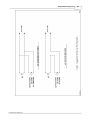
1
ASA-72 Hardware
Manual
Revision Date: 26 AUG 2006
This manual contains confidential information and
may only be reproduced or distributed with the
written consent of Apollo Security, Inc.
© 2008 Apollo Security Inc.
ASA-72 Hardware Manual
Advanced Electronic Controller For Apollo Access Control Systems
by Apollo Security Inc.
© 2008 Apollo Security Inc.
All rights reserved. No parts of this work may be reproduced in any form or by any means - graphic, electronic, or
mechanical, including photocopying, recording, taping, or information storage and retrieval systems - without the written
permission of Apollo Security, Inc.
While every precaution has been taken in the preparation of this document, Apollo Security assumes no responsibility
for errors or omissions, or for damages resulting from the use of information contained in this document or from the use
of programs and source code that may accompany it. In no event shall the publisher and the author be liable for any
loss of profit or any other commercial damage caused or alleged to have been caused directly or indirectly by this
document.
IMPORTANT INFORMATION
WARNING
HIGH VOLTAGE, AC MAIN POWER SHOULD ONLY BE CONNECTED BY QUALIFIED,
LICENSED ELECTRICIANS. ALL APPLICABLE LAWS AND CODES MUST BE FOLLOWED. IF
THIS PRECAUTION IS NOT OBSERVED, PERSONAL INJURY OR DEATH COULD OCCUR
Power should not be applied to the system until after the installation has been completed. If this
precaution is not observed, personal injury or death could occur, and the equipment could be
damaged beyond repair.
-Verify that the external circuit breaker which supplies power to the device power supply is turned off
prior to installation.
-Verify that the output voltage of the power supply is within specifications prior to connection to the
device.
CAUTION
Several important procedures should be followed to prevent electro-static discharge (ESD) damage
to sensitive CMOS integrated circuits and modules.
-All transport of electronic components, including completed reader assemblies, should be in static
shield packaging and containers.
-Handle all ESD sensitive components at an approved static controlled work station. These work
stations consist of a desk mat, floor mat and a ESD wrist strap. Work stations are available from
various vendors including the 3M company.
FCC Compliance Statement
This device complies with Part 15 of FCC Rules. Operation is subject to the following two conditions:
1.This device may not cause harmful interference, and
2.This device must accept any interference received, including interference that may cause
undesired operation.
This equipment has been tested and found to comply with the limits for a Class A digital device,
pursuant to Part 15 of the FCC Rules. These limits are designed to provide reasonable protection
against harmful interference when the equipment is operated in a commercial environment. This
equipment generates, uses, and can radiate radio frequency energy and, if not installed and used in
accordance with the instruction manual, may cause harmful interference to radio communications.
Operation of this device in a residential area is likely to cause harmful interference in which case the
user will be required to correct the interference at his/her own expense. The user is advised that any
equipment changes or modifications not expressly approved by the party responsible for compliance
would void the compliance to FCC regulations and therefore, the user's authority to operate the
equipment.
I
ASA-72 Hardware Manual
Table of Contents
2
Part I Introduction
1 Overview ................................................................................................................................... 2
2 General Features
................................................................................................................................... 2
4
Part II Hardware Layout
1 DIP Switches
................................................................................................................................... 4
DIP Switch Tables
......................................................................................................................................................... 4
DIP Switch Function
......................................................................................................................................................... 5
2 LEDs
................................................................................................................................... 5
Start Up Mode
......................................................................................................................................................... 5
Normal Operation
......................................................................................................................................................... 6
Host LED
......................................................................................................................................................... 6
3 Firmware ................................................................................................................................... 7
4 Additional...................................................................................................................................
Installation Information
7
Mounting
......................................................................................................................................................... 8
10
Part III System Wiring
1 Power
................................................................................................................................... 10
2 RS-485 Communication
...................................................................................................................................
Line
10
3 General Alarm
...................................................................................................................................
Inputs
10
Cabinet Tamper
......................................................................................................................................................... 10
Power Fault.........................................................................................................................................................
Input
10
Keyswitch/ACK
.........................................................................................................................................................
Switch Wiring (Optional)
10
Part IV Specifications
12
Part V Supplemental Figures
14
Part VI Table of Figures
24
Part VII Revision History
26
27
Index
© 2008 Apollo Security Inc.
Part
I
Introduction
2
1
ASA-72 Hardware Manual
Introduction
An access control system provides a means to replace traditional key and lock systems, which
are easy to defeat because of the ease of copying of keys and use by unauthorized personnel.
With electronic access control, the exact areas a person is able to access as well as during what
time is configurable through a central control system. In addition to the power of greater control, a
historical record is maintained which is useful in the case of a system security breach or for other
purposes including calculating work time and facility use costing.
1.1
Overview
The status panel provides alarm status monitoring for up to 72 alarm zones. The ASA-72 contains
an on board processor and a serial link (RS-485) for host communication.
The ASA-72 monitors and displays alarm, trouble, and non-alarm status.
It may also be
configured to display access control status and configuration information such as access granted,
access denied, duress, on-line, off-line, tamper, held-open, forced-open and auxiliary alarm.
The ASA-72 contains an audible alarm and provides front-panel switches for alarm
acknowledgement (ACK) and for LED test (TEST).
The ASA-72 processor is enclosed in a secure cabinet with an integral +5 Vdc power supply.
The power supply input selections are:
115 Vac (ASA-72, P/N 420-600)
230 Vac (ASA-72I, P/N 420-601)
24 Vdc (ASA-72D, P/N 420-602)
1.2
General Features
•
•
•
•
•
•
•
•
•
•
•
72 Tri-color LEDs
Monitors alarms, troubles, non-alarm, duress
Local acknowledgement
Local reset/LED test
Audible output upon new alarm or trouble
Supports 72 zones (4 sixteen zone alarm alarm input modules and reader alarms)
RS-485 serial communications
Host on-line LED
On-line communication LED for each alarm input module (4 total)
Monitors cabinet tamper
Monitors device power fail.
© 2008 Apollo Security Inc.
Part
II
Hardware Layout
4
ASA-72 Hardware Manual
2
Hardware Layout
2.1
DIP Switches
The ASA-72 has one block of DIP switches, with 8 switches. These switches are used to set
various configuration options for the interface. It is recommended to power the board down before
making any changes in the DIP switch settings as any changes will not take effect unless the
power is cycled.
2.1.1
DIP Switch Tables
5
OFF
OFF
OFF
OFF
OFF
OFF
OFF
OFF
OFF
OFF
OFF
OFF
OFF
OFF
OFF
Communications Address (SW1)
4
3
2
1
OFF OFF
OFF OFF
0
OFF OFF
OFF
ON
1
OFF OFF
ON
OFF
2
OFF OFF
ON
ON
3
OFF
ON
OFF OFF
4
OFF
ON
OFF
ON
5
OFF
ON
ON
OFF
6
OFF
ON
ON
ON
7
ON
OFF
OFF OFF
8
ON
OFF
OFF
ON
9
ON
OFF
ON
OFF
10
ON
OFF
ON
ON
11
ON
ON
OFF OFF
12
ON
ON
OFF
ON
13
ON
ON
ON
OFF
14
OFF
ON
ON
ON
ON
ON
ON
ON
ON
ON
ON
ON
ON
ON
ON
ON
ON
ON
OFF
OFF
OFF
OFF
OFF
OFF
OFF
OFF
ON
ON
ON
ON
ON
ON
ON
ON
ON
OFF
OFF
OFF
OFF
ON
ON
ON
ON
OFF
OFF
OFF
OFF
ON
ON
ON
ON
ON
OFF
OFF
ON
ON
OFF
OFF
ON
ON
OFF
OFF
ON
ON
OFF
OFF
ON
ON
ON
OFF
ON
OFF
ON
OFF
ON
OFF
ON
OFF
ON
OFF
ON
OFF
ON
OFF
ON
© 2008 Apollo Security Inc.
15
16
17
18
19
20
21
22
23
24
25
26
27
28
29
30
31
Hardware Layout
5
Baud Rate
2
3
300
OFF
OFF
1200
OFF
ON
2400
ON
OFF
9600
ON
ON
Note: Switch 8 is not used.
Table 2. 1: ASA-72 DIP Switch Settings
2.1.2
DIP Switch Function
Communications Address—Sets the address that identifies the device on the communications
line. This number must be unique for each device on a single RS-485 communications line.
Baud Rate—Specifies the baud rate for the serial line of interface. This setting must be the
same for all devices on the communication line connected to this port.
Table 2.1.1 : DIP Switch Function
2.2
LEDs
The ASA-72 has 77 LEDs on the front panel for use in monitoring functioning of panel,
annunciating alarms and for diagnosis of problems. The LEDs function in two modes: startup and
normal operation
2.2.1
Start Up Mode
Immediately after powering on the panel, the start-up test will initiate and the results will be
displayed on the LEDs. If there are no failures, the test will progress If the panel encounters an
error, it will stop with the failed test and display the LED sequence corresponding to that test. The
first sequence tests the internal logic:
© 2008 Apollo Security Inc.
Test
A1
A2
A3
A4
Initilization
ON
OFF
OFF
OFF
Internal RAM
ON
ON
OFF
OFF
External RAM
ON
ON
ON
OFF
PROM CRC Check
ON
ON
ON
ON
6
ASA-72 Hardware Manual
Table 2. 2: AIM-2SL Start up LED Function
After the logic test, the LED test will test all LEDs for proper operation:
1. All LEDs ON Green, .5 second (Including ON LINE LEDs)
2. All LEDs ON Orange, .5 second
3. All LEDs ON Red, .5 second
4. Buzzer ON for .5 second and HOST LED ON for 1 second.
2.2.2
Normal Operation
After initialization and self tests, the LEDs will switch to normal operation and will display
information about the panel operation.
A single tri-color LED per zone indicates Red for Alarm, Orange for Trouble, and Green for
Non-alarm. The LEDs are organized as 4 columns (A,B,C,D,) of 19 each. The LEDs of rows 1-18
are tri-color to display alarm/reader status. LEDs of row 19 (ONLINE) are Green, and show
general panel status. Name plate inserts are provided adjacent to each LED column for user
defined text to describe LED function (See Figure 61).
2.2.3
Host LED
The Green HOST LED indicates the status of communication between the ASA-72 and host (see
Figure 55). The HOST LED functions in two modes: NORMAL mode and TEST mode.
In NORMAL mode, the LED has four states.
below:
The four states and the LED activity are shown
State
LED Activity
Communication Normal
Solid Green
Comm Lost (Request For
Acknowledgement generated)
Slow Blink (1 per sec)
Comm Lost (Being acknowledged)
Fast Blink (5 per sec)
Comm Lost (Acknowledged)
Heart beat
(1 per 5 sec)
In TEST mode, the LED shows the communication activity. TEST mode is entered by depressing
and holding down the TEST push button. When the TEST button is detected as depressed, the
HOST LED will turn on for 1 second to fulfill the LED test function, then, the HOST LED will follow
the host communication activity. TEST mode is exited when the test button is released.
© 2008 Apollo Security Inc.
Hardware Layout
2.3
7
Firmware
PROM Label Information
The PROM that contains the program is labeled with information to identify the program and the
product with which it operates. The following is a sample of a typical PROM label and a
description of the various fields within the label.
ASA-72
101079-04/B
COPYRIGHT 1994
APOLLO: B8FD
ASA-72—This is the product that this program intended to be used in.
101079-04-B—This is the part number of the PROM. The field after the second dash is
the revision of this version of program. This field will change if the program is updated.
COPYRIGHT 1995—The year of the program copyright.
APOLLO: B8FD—The 4 characters after the colon is the program checksum.
number uniquely identifies each different program.
This
PROM Installation
Remove the old PROM from location U7 (see Figure 101) by prying it out of its socket with a blunt
object such as a flat blade screwdriver or with a PROM removal tool. Use care to not damage the
circuit board or surrounding components. Do not damage the old PROM, it can be erased and
re-used, and should be returned.
The new PROM can now be installed in its socket. Please note the direction of the notch on
Figure 56. The new chip must be installed with the notch in this position. Failure to install the
chip with the correct orientation will result in destruction of the chip and possible damage to the
ASA-72. The new chip may require its pins be bent inward slightly before it will fit into the socket.
Apply power to the ASA-72 and verify correct operation of the program update.
2.4
Additional Installation Information
© 2008 Apollo Security Inc.
8
2.4.1
ASA-72 Hardware Manual
Mounting
Enclosure Mounting
The ASA-72 enclosure is a steel cabinet which is designed for mounting on a wall. Four mounting
holes are provided in the enclosure. See Figure 54 for mounting hole locations.
Power Supply Mounting
Mount the power supply in the cabinet using the #6 hardware provided, as shown in Figure 54.
Fasten the supply to the cabinet mounting studs using hex nuts, split lock washers and flat
washers.
Connect the green Ground wire to the dedicated ground stud (GND), using a #6 hex nut with an
internal star washer between the terminal lug and the cabinet wall.
© 2008 Apollo Security Inc.
Part
III
System Wiring
10
3
ASA-72 Hardware Manual
System Wiring
NOTE—Use tie-wraps (supplied) to provides strain relief for all wiring.
3.1
Power
Route the input voltage wiring through any one of the four knockouts provided in the enclosure.
Snap-off the protective terminal block cover (where applicable) and connect to the terminal block
as shown in Figure 59. Connect the +5V and + RETURN wires to the terminal block and replace
the cover.
Connect a UPS as shown in Figure 60.
3.2
RS-485 Communication Line
The ASA-72 is equipped with an RS-485 interface. It communicates with other devices with
RS-485 interface in a multi-dropped configuration. The main RS-485 run (4000 feet max.) must
use low capacitance shielded cable with 2 twisted pairs having a characteristic impedance of 120
Ohms (Belden 9842 or equivalent). Carefully insulate the shield drain wire (SG) with sleeving for
a reliable installation.
Line terminators (ATM-48, P/N 470-030) must be installed at the ends of the communication lines
for reliable data transmission .
Route the RS-485 cable into the enclosure through a suitable knockout and connect the RS-485
communication lines as indicated in Figure 58.
3.3
General Alarm Inputs
The ASA-72 provides two general alarm inputs. The wiring to the input should be made with
twisted pair 24 AWG wire. If these input is not used, it should be ‘jumpered’ using a 1” (25 mm)
long piece of wire connecting the two terminals to form a closed circuit. This will prevent an alarm
condition being reported to the host.
3.3.1
Cabinet Tamper
The cabinet tamper switch is pre-wired as shown in Figure 57.
3.3.2
Power Fault Input
Power fault is sensed when the ASA-72 system is powered from a UPS. Route the wires (24
AWG or larger) through a convenient knockout and terminate them as shown in Figure 57.
3.3.3
Keyswitch/ACK Switch Wiring (Optional)
Two ACK push button wiring options, using a customer-supplied keyswitch, are shown in Figure
62.
The auto-acknowledge wiring option supplies the switch closure from the keyswitch, rather than
from the ACK push button, thereby providing a permanent acknowledgement.
The enable/disable option provides secure control of the ACK push button.
© 2008 Apollo Security Inc.
Part
IV
Specifications
12
4
ASA-72 Hardware Manual
Specifications
Power Requirements:
115
230
24
5
Vac
Vac
Vdc
Vdc
@
@
@
@
0.2A
0.1A
0.5A
1.5A for
for
ASA-72
for
ASA-72I
for
ASA-72D
ASA Processor
Dimensions:
16 in. (width) x 16 in. (Height) x 5 in. (Depth)
Weight (with power supply)—24 lb.
Environment:
Temperature—0-50 degrees C
Relative Humidity—0-95% non condensing
© 2008 Apollo Security Inc.
Part
V
Supplemental
Figures
14
5
ASA-72 Hardware Manual
Supplemental Figures
© 2008 Apollo Security Inc.
Supplemental Figures
© 2008 Apollo Security Inc.
15
16
ASA-72 Hardware Manual
© 2008 Apollo Security Inc.
Supplemental Figures
© 2008 Apollo Security Inc.
17
18
ASA-72 Hardware Manual
© 2008 Apollo Security Inc.
Supplemental Figures
© 2008 Apollo Security Inc.
19
20
ASA-72 Hardware Manual
© 2008 Apollo Security Inc.
Supplemental Figures
© 2008 Apollo Security Inc.
21
22
ASA-72 Hardware Manual
© 2008 Apollo Security Inc.
Part
VI
Table of Figures
24
6
ASA-72 Hardware Manual
Table of Figures
Number
54
55
57
58
59
60
61
62
63
Description
Enclosure with Power Supply
Front View
Cabinet Tamper/Power Fault Wiring
RS-485 Communication Wiring
Power Supply Wiring
24 Volt UPS/DC to DC Connector Wiring
Legend Insert
Suggested Wiring for ACK/Keyswitch
Typical Application
Page
15
16
17
18
19
20
21
22
23
© 2008 Apollo Security Inc.
Part
VII
Revision History
26
7
ASA-72 Hardware Manual
Revision History
REVISION HISTORY
Revision
Date
A
B
24 OCT 1996
26 AUG 2006
Description of changes
Initial Release
Rewrite and Accuracy Review
Editor
D. Long
R. Burnside
© 2008 Apollo Security Inc.
Index
Index
-AAccess Control
2
-BBaud Rate
5
-DDimensions
12
-FFirmware (PROM)
7
-LLEDs
5
-OOperating Environment
-SSelf Test 5
Specifications
Start Up Mode
12
5
-TTest sequence
5
© 2008 Apollo Security Inc.
12
27